1993 DODGE TRUCK brake pads
[x] Cancel search: brake padsPage 31 of 1502

0 - 12
LUBRICATION
AND
MAINTENANCE
• A vehicle equipped with SAE approved sling-type
towing equipment can be used (Fig. 10). However,
many vehicles are equipped with air dams, spoilers, and/or ground effect panels. In this case a wheel-lift
towing vehicle or a flat-bed hauling vehicle is recom mended (Fig. 10). If a flat bed device is used, the ap
proach angle should not exceed 15 degrees.
GROUND CLEARANCE The lifted wheels of the disabled vehicle should be
a minimum of 10 cm (4 in.) off the ground. Make
sure there is enough clearance at the opposite end.
This is critical when towing over rough terrain. If necessary, the rear ground clearance can be increased by removing the wheels from the lifted end
and then towing with the lifted end closer to the
ground. If the rear wheels are removed, secure the
brake drums. A 20 cm (8 in.) ground clearance must
be maintained between brake drums or rotors and the ground.
SAFETY PRECAUTIONS The following safety precautions must be consid
ered when preparing for and during a vehicle towing operation:
• Remove exhaust pipe tips that interfere with the
tow sling and crossbar • Padding should be placed between the tow sling/
crossbar and any painted surfaces
• If the vehicle is damaged, secure the loose and pro
truding parts
• Always use a safety chain system that is indepen dent of the lifting and towing equipment
• When placing tow hooks on the rear axle, position them so they do not damage the brake tubing or
hoses
• Do not allow any of the towing equipment to con
tact the fuel tank
• Do not tow the vehicle by connecting to the front
or rear shock absorbers
• The operator should not go under a vehicle while
it is lifted by the towing equipment. The vehicle
should first be supported by safety stands
• Do not allow passengers in a vehicle being towed
• Observe all state and local laws involving warning signals, night illumination, speed, etc.
• Do not exceed a towing speed of 48 km/h (30 mph)
• Avoid towing distances of more than 24 km (15
miles) whenever possible • Do not attach tow chains or a tow sling to a
bumper, the steering linkage, the universal joints, or a drive shaft
REAR-END RAISED TOWING It is recommended that the rear-end raised towing
method be used. Vehicles can be towed with the front
wheels on the ground for extended distances at speeds not exceeding 48 km/h (30 mph) (Fig. 11). (1) Attach the J-hooks around the axle shaft tubes
outboard of the rear springs. (2) Position and center the sling under and for
ward of the rear bumper. (3) Attach safety chains (with pads) at each end of
the rear bumper.
(4) Turn the ignition switch to the OFF position to
unlock the steering wheel. (5) Clamp the steering wheel with the front wheels
in the straight ahead position.
CAUTION:
Do not use the steering
column
lock
to
secure
front
wheel
in the straight-ahead
position.
(6) Shift the transmission to NEUTRAL.
POSITION CENTER BAR FORWARD
OF
BUMPER
-
/
J-HOOKS OUTBOARD
OF
SPRINGS
RN967A
Fig. 11 Rear-End
Raised
Towing
FRONT'END RAISED TOWING If a vehicle cannot be towed from the rear, the
front-end raised towing method normally can be
used (Fig. 12). (1) Center the sling with the bumper and position
it at the frame front crossmember.
CAUTION:
Use tow
chains
with
J-hooks
for
con
necting
to the
disabled
vehicle's
lower
suspension
arms.
Never use
T-hooks.
(2) Route the J-hooks and tow chains over the
steering linkage outboard of the coil spring.
(3) Attach the J-hooks to the outer end of the
lower suspension arms.
(4) Raise the vehicle.
(5.) Attach the safety chains to the disabled vehicle
at the frame rails.
Vehicles equipped with a MANUAL TRANSMIS
SION can be towed with the rear wheels on the
Page 49 of 1502
0 - 30
LUBRICATION
AND
MAINTENANCE
— - •
Fig.
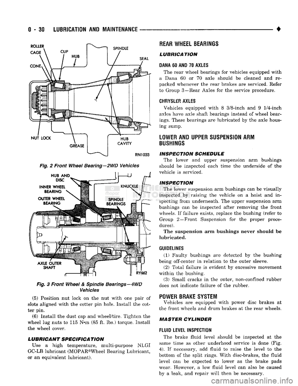
2 Front
Wheel
Bearing—2WD Vehicles
Fig.
3 Front
Wheel
&
Spindle
Bearings—4WD
Vehicles
(5) Position nut lock on the nut with one pair of
slots aligned with the cotter pin hole. Install the cot
ter pin.
(6) Install the dust cap and wheel/tire. Tighten the
wheel lug nuts to 115 N*m (85 ft. lbs.) torque. Install
the wheel cover.
LUBRICANT SPECIFICATION
Use a high temperature, multi-purpose NLGI
GC-LB lubricant (MOPAR®Wheel Bearing Lubricant,
or an equivalent lubricant).
REAR
WHEEL BEARINGS
LUBRICATION
DANA
60
AND
70
AXLES
The rear wheel bearings for vehicles equipped with
a Dana 60 or 70 axle should be cleaned and re
packed whenever the rear brakes are serviced. Refer
to Group 3—Rear Axles for the service procedure.
CHRYSLER
AXLES
, Vehicles equipped with 8 3/8-inch and 9
1/4-inch
axles have axle shaft bearings instead of wheel bear
ings.
These bearings are lubricated by the axle hous
ing sump.
LOWER
AND UPPER
SUSPENSION
ARM
BUSHINGS
INSPECTION
SCHEDULE
The lower and upper suspension arm bushings
should be inspected each time the underside of the
vehicle is serviced.
INSPECTION
The lower suspension arm bushings can be visually
inspected by raising the vehicle on a hoist and in specting from underneath. The upper suspension arm
bushings can be inspected after removing the front wheels. If failure exists, replace the bushing (refer to Group 2—Front Suspension for the proper proce
dures).
The suspension arm bushings never should be
lubricated.
GUIDELINES
(1) Faulty bushings are detected by the bushing
being off-center in relation to the outer sleeve.
(2) Total failure is evident by excessive movement
within the bushing.
(3)
Small cracks in the outer, non-confined rubber
does not indicate failure of the rubber. '
POWER BRAKE SYSTEM
Vehicles are equipped with power disc brakes at
the front wheels and drum brakes at the rear wheels.
MASTER CYLINDER
FLUID
LEVEL INSPECTION
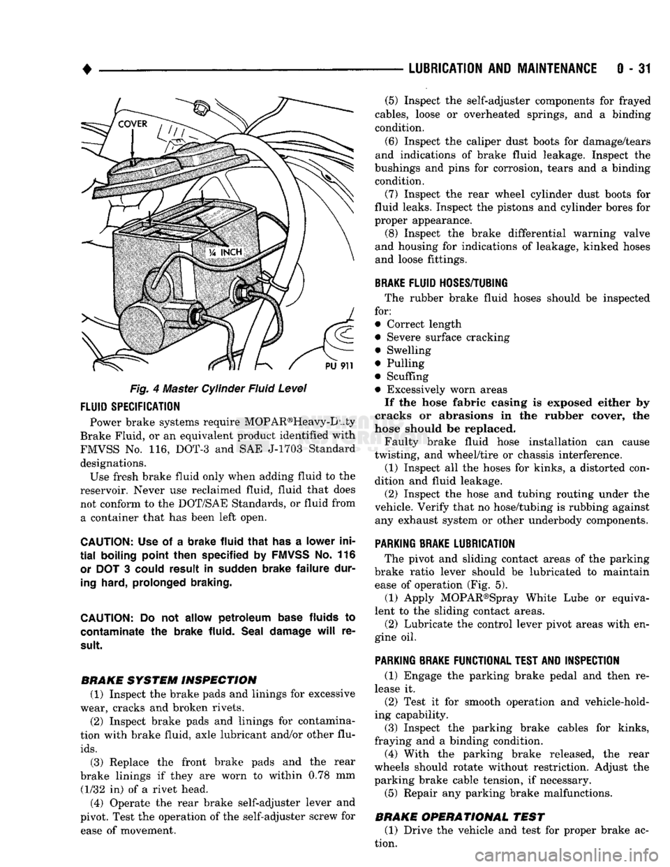
The brake fluid level should be inspected at the
same time as other underhood service is done (Fig.
4).
If necessary, add fluid to raise the level to the
bottom of the split rings. With disc-brakes, the fluid level can be expected to lower as the brake pads
wear. However, a low fluid level can also be caused
by a leak, and repair will then be necessary.
Page 50 of 1502
•
LUBRICATION
AND
MAINTENANCE
0 - 31
Fig. 4 Master Cylinder Fluid Level
FLUID
SPECIFICATION
Power brake systems require MOP AR®Heavy-D uty
Brake Fluid, or an equivalent product identified with
FMVSS No. 116, DOT-3 and SAE J-1703 Standard designations. Use fresh brake fluid only when adding fluid to the
reservoir. Never use reclaimed fluid, fluid that does not conform to the DOT/SAE Standards, or fluid from a container that has been left open.
CAUTION:
Use of a
brake fluid that
has a
lower ini
tial
boiling point then specified
by
FMVSS
No. 116
or
DOT 3
could result
in
sudden brake failure dur
ing
hard, prolonged braking.
CAUTION:
Do not
allow petroleum base
fluids
to
contaminate
the
brake fluid. Seal damage
will
re
sult.
BRAKE SYSTEM INSPECTION (1) Inspect the brake pads and linings for excessive
wear, cracks and broken rivets.
(2) Inspect brake pads and linings for contamina
tion with brake fluid, axle lubricant and/or other flu
ids.
(3) Replace the front brake pads and the rear
brake linings if they are worn to within 0.78 mm (1/32 in) of a rivet head.
(4) Operate the rear brake self-adjuster lever and
pivot. Test the operation of the self-adjuster screw for ease of movement. (5) Inspect the self-adjuster components for frayed
cables, loose or overheated springs, and a binding
condition.
(6) Inspect the caliper dust boots for damage/tears
and indications of brake fluid leakage. Inspect the
bushings and pins for corrosion, tears and a binding condition.
(7) Inspect the rear wheel cylinder dust boots for
fluid leaks. Inspect the pistons and cylinder bores for
proper appearance. (8) Inspect the brake differential warning valve
and housing for indications of leakage, kinked hoses and loose fittings.
BRAKE
FLUID
HOSES/TUBING
The rubber brake fluid hoses should be inspected
for:
• Correct length
• Severe surface cracking
• Swelling
• Pulling
• Scuffing
• Excessively worn areas If the hose fabric casing is exposed either by
cracks or abrasions in the rubber cover, the
hose should be replaced.
Faulty brake fluid hose installation can cause
twisting, and wheel/tire or chassis interference.
(1) Inspect all the hoses for kinks, a distorted con
dition and fluid leakage. (2) Inspect the hose and tubing routing under the
vehicle. Verify that no hose/tubing is rubbing against any exhaust system or other underbody components.
PARKING
BRAKE
LUBRICATION
The pivot and sliding contact areas of the parking
brake ratio lever should be lubricated to maintain ease of operation (Fig. 5).
(1) Apply MOPAR®Spray White Lube or equiva
lent to the sliding contact areas.
(2) Lubricate the control lever pivot areas with en
gine oil.
PARKING
BRAKE
FUNCTIONAL
TEST
AND
INSPECTION
(1) Engage the parking brake pedal and then re
lease it. (2) Test it for smooth operation and vehicle-hold
ing capability.
(3) Inspect the parking brake cables for kinks,
fraying and a binding condition. (4) With the parking brake released, the rear
wheels should rotate without restriction. Adjust the
parking brake cable tension, if necessary.
(5) Repair any parking brake malfunctions.
BRAKE OPERATIONAL TEST (1) Drive the vehicle and test for proper brake ac
tion.
Page 85 of 1502
2
- 32
FRONT
SUSPENSION
AND
AXLE
• (5) Disconnect flexible brake fluid hose fittings at
the frame crossmember. Plug the hoses at the fit
tings.
(6) Remove the shock absorber lower nut and stud
from the axle shaft tube bracket. Remove the nuts and disconnect the stabilizer bar links from the
spring brackets.
(7) Disconnect the vacuum hoses and wiring con
nections from the shift motor housing.
(8) Remove nuts and the washers from the spring
U-bolts. Remove the complete front axle from the ve
hicle.
INSTALLATION
(1) Position the front axle under the front of the
vehicle with the axle spring pads under the springs.
Place the spring brackets over the springs. Make sure the stabilizer bar link bolt holes face toward the
rear of the vehicle.
(2) Install the spring U-bolts, washers and nuts.
Refer to Front Suspension — 4WD Vehicles within
this group. (3) Install the shock absorber. Refer to Front Sus
pension — 4WD Vehicles within this group. (4) Connect the stabilizer bar links to the spring
brackets. Refer to Front Suspension-4WD Vehicles
within this group.
(5) Remove plugs and connect the brake hose fit
tings.
Refer to Group 5, Brakes. (6) Connect the drag-link ball stud to the steering
knuckle arm. Refer to Group 19, Steering. (7) Connect the drive shaft to the pinion yoke with
the installation reference marks aligned. Install the
washers and the nuts and tighten to 19 N*m (14 ft. lbs.) torque.
(8) Connect the vacuum hoses and wiring connec
tions to the shift motor housing. (9) Remove the supports, lower the vehicle and re
move the block from the brake pedal.
(10) Raise the vehicle.
• Bleed and adjust the brakes
• Lubricate all the ball stud fittings
• Inspect the differential housing lubricant level. Re
fer to Group 0, Lubrication and Maintenance. (11) Lower the vehicle and test the axle and sus
pension operation.
DIFFERENTIAL
DISASSEMBLY
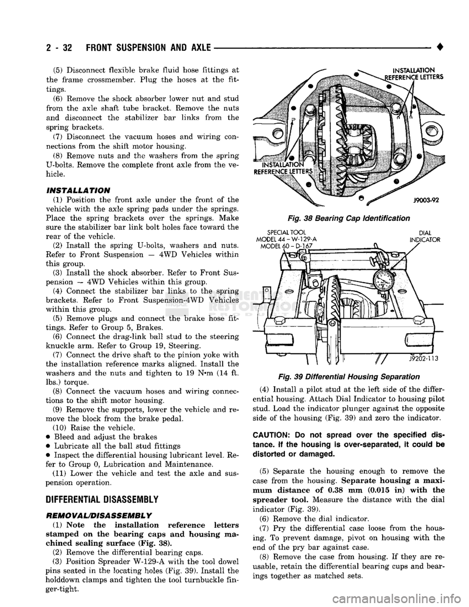
REMOVAL/DISASSEMBLY (1) Note the installation reference letters
stamped on the bearing caps and housing ma
chined sealing surface (Fig. 38). (2) Remove the differential bearing caps.
(3) Position Spreader W-129-A with the tool dowel
pins seated in the locating holes (Fig. 39). Install the
holddown clamps and tighten the tool turnbuckle fin ger-tight.
INSTALLATION
EFERENCE
LETTERS
J9003-92
Fig.
38 Bearing Cap
Identification
SPECIAL
TOOL
MODEL
44-W-129-A
MODEL
60-D-167
DIAL
INDICATOR
«ar"P—
J9202-113
Fig.
39
Differential
Housing
Separation
(4) Install a pilot stud at the left side of the differ
ential housing. Attach Dial Indicator to housing pilot stud. Load the indicator plunger against the opposite
side of the housing (Fig. 39) and zero the indicator.
CAUTION:
Do not
spread
over the specified
dis
tance.
If the
housing
is over-separated, it
could
be distorted or
damaged.
(5) Separate the housing enough to remove the
case from the housing. Separate housing a maxi
mum distance of 0.38 mm (0.015 in) with the spreader tool. Measure the distance with the dial
indicator (Fig. 39).
(6) Remove the dial indicator.
(7) Pry the differential case loose from the hous
ing. To prevent damage, pivot on housing with the end of the pry bar against case.
(8) Remove the case from housing. If they are re
usable, retain the differential bearing cups and bear ings together as matched sets.
Page 112 of 1502
•
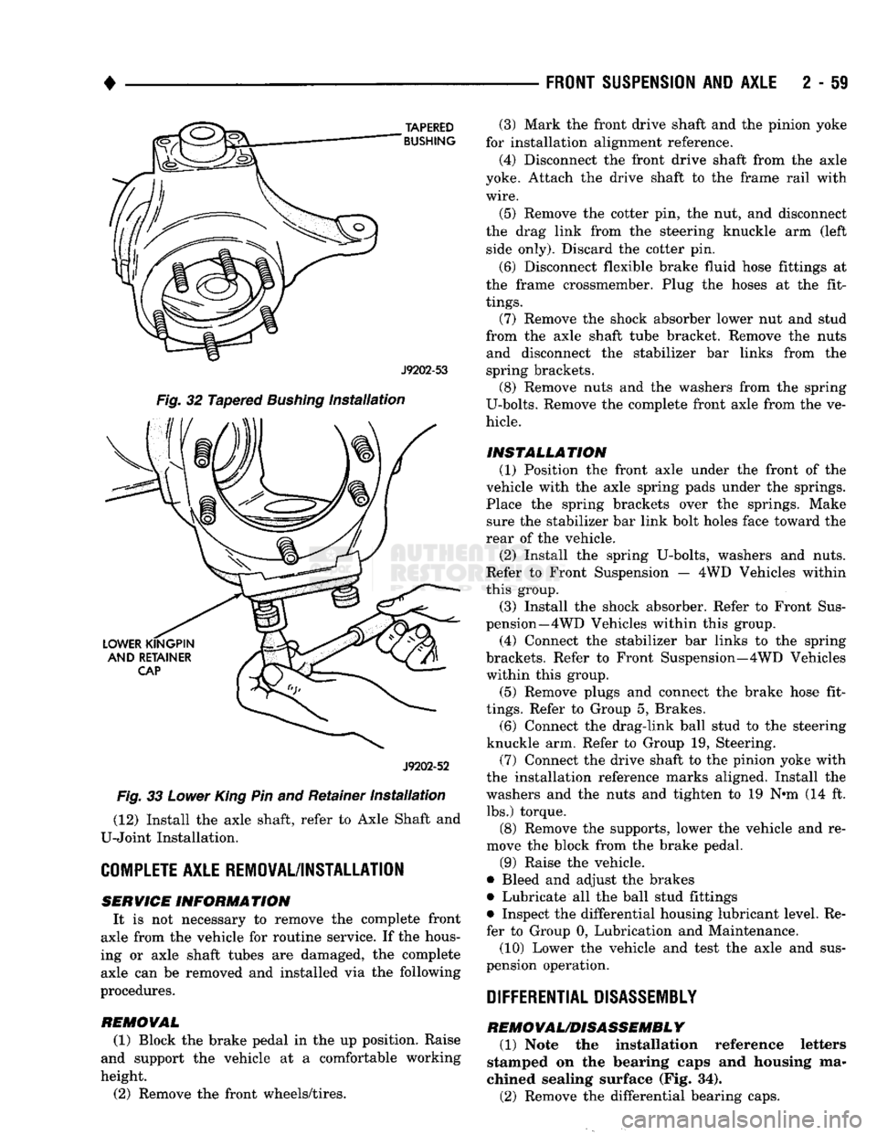
TAPERED
BUSHING
J9202-53
Fig.
32 Tapered
Bushing
Installation
J9202-52
Fig.
33
Lower
King
Pin and Retainer
Installation
(12) Install the axle shaft, refer to Axle Shaft and
U-Joint Installation.
COMPLETE
AXLE REMOVAL/INSTALLATION SERVICE
INFORMATION
It is not necessary to remove the complete front
axle from the vehicle for routine service. If the hous
ing or axle shaft tubes are damaged, the complete axle can be removed and installed via the following
procedures.
REMOVAL
(1) Block the brake pedal in the up position. Raise
and support the vehicle at a comfortable working
height.
(2) Remove the front wheels/tires.
FRONT SUSPENSION
AND
AXLE
2 - 59
(3) Mark the front drive shaft and the pinion yoke
for installation alignment reference.
(4) Disconnect the front drive shaft from the axle
yoke. Attach the drive shaft to the frame rail with
wire.
(5) Remove the cotter pin, the nut, and disconnect
the drag link from the steering knuckle arm (left side only). Discard the cotter pin.
(6) Disconnect flexible brake fluid hose fittings at
the frame crossmember. Plug the hoses at the fit
tings.
(7) Remove the shock absorber lower nut and stud
from the axle shaft tube bracket. Remove the nuts and disconnect the stabilizer bar links from the
spring brackets. (8) Remove nuts and the washers from the spring
U-bolts. Remove the complete front axle from the ve
hicle.
INSTALLATION (1) Position the front axle under the front of the
vehicle with the axle spring pads under the springs.
Place the spring brackets over the springs. Make sure the stabilizer bar link bolt holes face toward the
rear of the vehicle.
(2) Install the spring U-bolts, washers and nuts.
Refer to Front Suspension — 4WD Vehicles within
this group. (3) Install the shock absorber. Refer to Front Sus
pension—4 WD Vehicles within this group.
(4) Connect the stabilizer bar links to the spring
brackets. Refer to Front Suspension—4WD Vehicles within this group.
(5) Remove plugs and connect the brake hose fit
tings.
Refer to Group 5, Brakes. (6) Connect the drag-link ball stud to the steering
knuckle arm. Refer to Group 19, Steering. (7) Connect the drive shaft to the pinion yoke with
the installation reference marks aligned. Install the
washers and the nuts and tighten to 19 N-m (14 ft. lbs.) torque.
(8) Remove the supports, lower the vehicle and re
move the block from the brake pedal.
(9) Raise the vehicle.
• Bleed and adjust the brakes
• Lubricate all the ball stud fittings
• Inspect the differential housing lubricant level. Re
fer to Group 0, Lubrication and Maintenance.
(10) Lower the vehicle and test the axle and sus
pension operation.
DIFFERENTIAL DISASSEMBLY
REMOVAL/DISASSEMBLY
(1) Note the installation reference letters
stamped on the bearing caps and housing ma
chined sealing surface (Fig. 34).
(2) Remove the differential bearing caps.
Page 194 of 1502
•
BRAKES
i - 7
BRAKE
ADJUSTMENTS-BRAKE
BLEEDING
INDEX
page
Brake
Fluid and Level 7
Brake
System
Bleeding 8
Rear
Brake
Adjustment 7
BRAKE
FLUID
AND
LEWEL
RECOMMENDED
FLUID The only brake fluid recommended for AD models
is Mopar brake fluid, or an equivalent fluid meeting SAE
J1703
and DOT 3 standards.
Use new brake fluid only, to top off the master
cylinder or refill the system* Never use re
claimed fluid, fluid not meeting the
SAE/DOT
standards, fluid marked 70R1, or fluid from a
container that has been left open for any length
of time. Using non recommended or unspecified
fluid can result in brake failure after hard pro longed braking.
BRAKE
FLUID
LEWEL Always clean the master cylinder cover before
checking fluid level. If not cleaned, dirt from the
cover could enter the fluid. Also check the cover seal
and replace it if torn or distorted.
Correct fluid level is to the bottom of the ring in
dicators on models with a plastic reservoir and to
within 1/4 inch of the reservoir rim on all others. If necessary, add fluid to bring up to the proper level.
Note that on disc brake equipped vehicles, fluid level can be expected to fall as the brake pads wear.
BRAKE
FLUID
CONTAMINATION
Oil in the fluid will cause brake system rubber
seals to soften and swell. The seals may also become
porous and begin to deteriorate.
If fluid contamination is suspected, drain off a sam
ple from the master cylinder. A suction gun or simi lar device can be used for this purpose.
Empty the drained fluid into a glass container.
Contaminants in the fluid will cause the fluid to sep
arate into distinct layers. If contamination has oc
curred, the system rubber seals, hoses and cups must
be replaced and the system thoroughly flushed with clean brake fluid.
Remember that brake fluid tends to darken
over time. Do not confuse this normal condition
with contamination.
REAR
BRAKE
ADJUSTMENT
The rear drum brakes are equipped with a self ad
justing mechanism. Under normal circumstances, the only time adjustment is required is when the brake-
page
Stop
Light Switch Adjustment 9
Wheel
Nut Tightening 9
shoes are replaced; removed for access to other parts; or when one or both drums are replaced.
Adjustment can be performed with a standard
brake gauge or with adjusting tool C-3784.
ADJUSTMENT
WITH
STANDARD
BRAKE
GAUGE
(1) Verify that left/right automatic adjuster lever
and cable are properly connected and that parking
brakes are fully released. Be sure there is slack in cables.
(2) Insert brake gauge in drum. Expand gauge un
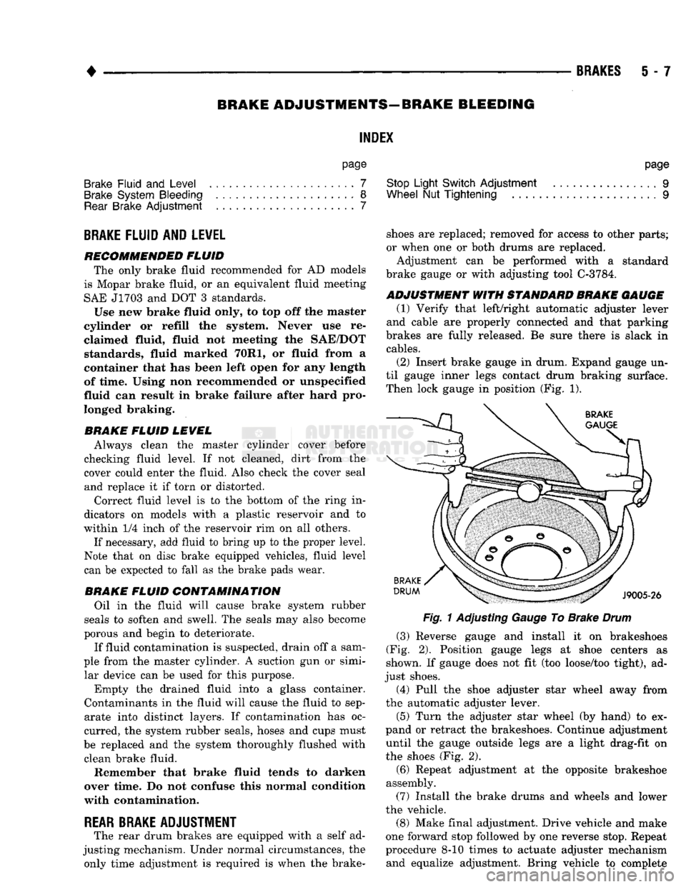
til gauge inner legs contact drum braking surface. Then lock gauge in position (Fig. 1).
Fig.
1 Adjusting Gauge To Brake
Drum
(3) Reverse gauge and install it on brakeshoes
(Fig. 2). Position gauge legs at shoe centers as
shown. If gauge does not fit (too loose/too tight), ad
just shoes. (4) Pull the shoe adjuster star wheel away from
the automatic adjuster lever.
(5) Turn the adjuster star wheel (by hand) to ex
pand or retract the brakeshoes. Continue adjustment until the gauge outside legs are a light drag-fit on
the shoes (Fig. 2).
(6) Repeat adjustment at the opposite brakeshoe
assembly. (7) Install the brake drums and wheels and lower
the vehicle.
(8) Make final adjustment. Drive vehicle and make
one forward stop followed by one reverse stop. Repeat
procedure 8-10 times to actuate adjuster mechanism and equalize adjustment. Bring vehicle to complete
Page 234 of 1502
BRAKES
5 - 47
(8) Disengage and remove adjuster screw assembly
from brakeshoes.
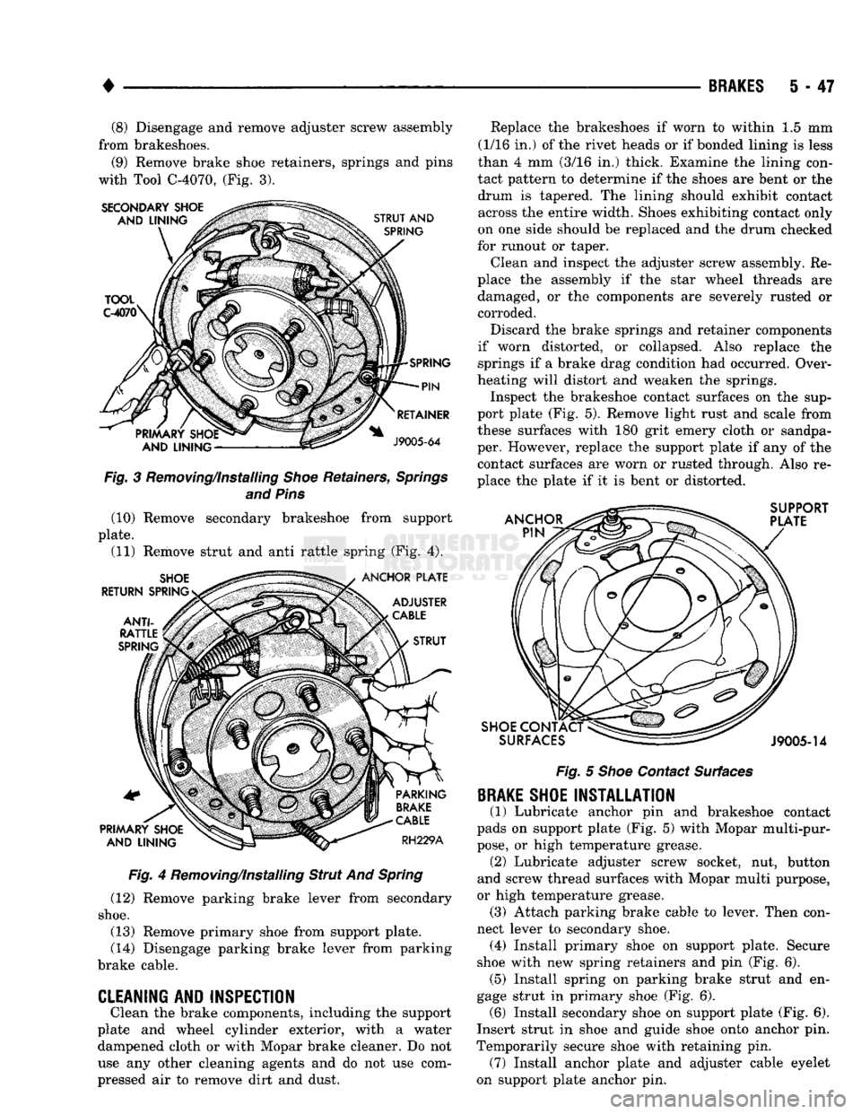
(9) Remove brake shoe retainers, springs and pins
with Tool C-4070, (Fig. 3). Fig. 3 Removing/Installing Shoe Retainers, Springs
and Pins (10) Remove secondary brakeshoe from support
plate. (11) Remove strut and anti rattle spring (Fig. 4).
Fig. 4 Removing/Installing Strut And Spring
(12) Remove parking brake lever from secondary
shoe.
(13) Remove primary shoe from support plate.
(14) Disengage parking brake lever from parking
brake cable.
CLEANING AND INSPECTION
Clean the brake components, including the support
plate and wheel cylinder exterior, with a water dampened cloth or with Mopar brake cleaner. Do not
use any other cleaning agents and do not use com
pressed air to remove dirt and dust. Replace the brakeshoes if worn to within 1.5 mm
(1/16 in.) of the rivet heads or if bonded lining is less
than 4 mm (3/16 in.) thick. Examine the lining con
tact pattern to determine if the shoes are bent or the drum is tapered. The lining should exhibit contact across the entire width. Shoes exhibiting contact only
on one side should be replaced and the drum checked
for runout or taper.
Clean and inspect the adjuster screw assembly. Re
place the assembly if the star wheel threads are damaged, or the components are severely rusted or corroded.
Discard the brake springs and retainer components
if worn distorted, or collapsed. Also replace the springs if a brake drag condition had occurred. Over
heating will distort and weaken the springs. Inspect the brakeshoe contact surfaces on the sup
port plate (Fig. 5). Remove light rust and scale from
these surfaces with 180 grit emery cloth or sandpa
per. However, replace the support plate if any of the contact surfaces are worn or rusted through. Also re
place the plate if it is bent or distorted.
Fig. 5 Shoe Contact Surfaces
BRAKE
SHOE INSTALLATION
(1) Lubricate anchor pin and brakeshoe contact
pads on support plate (Fig. 5) with Mopar multi-pur
pose,
or high temperature grease. (2) Lubricate adjuster screw socket, nut, button
and screw thread surfaces with Mopar multi purpose,
or high temperature grease. (3) Attach parking brake cable to lever. Then con
nect lever to secondary shoe. (4) Install primary shoe on support plate. Secure
shoe with new spring retainers and pin (Fig. 6). (5) Install spring on parking brake strut and en
gage strut in primary shoe (Fig. 6). (6) Install secondary shoe on support plate (Fig. 6).
Insert strut in shoe and guide shoe onto anchor pin.
Temporarily secure shoe with retaining pin. (7) Install anchor plate and adjuster cable eyelet
on support plate anchor pin.
Page 240 of 1502
•
BRAKES
5 - 53
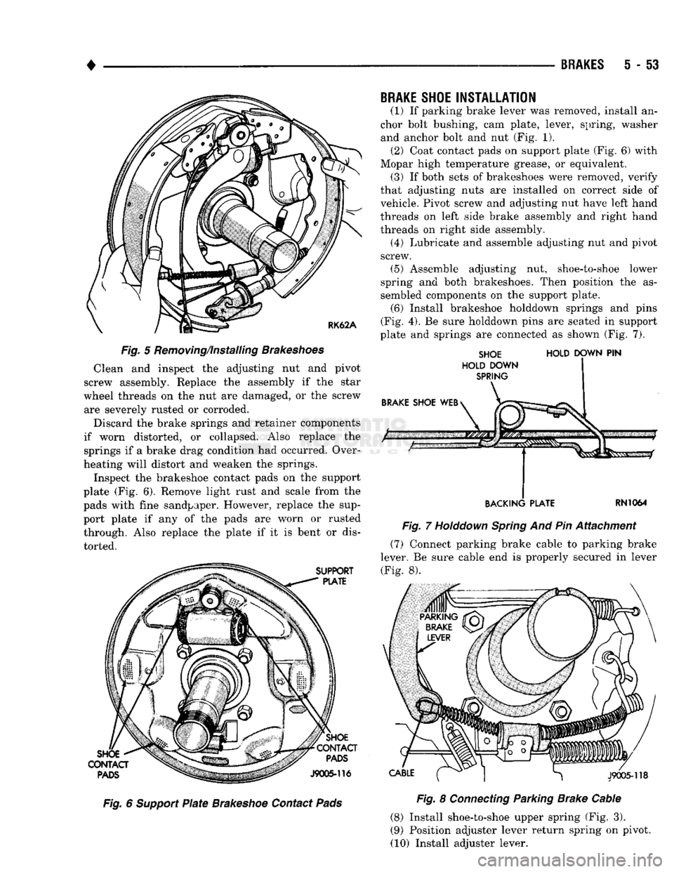
Fig.
5 Removing/installing
Brakeshoes
Clean and inspect the adjusting nut and pivot
screw assembly. Replace the assembly if the star
wheel threads on the nut are damaged, or the screw are severely rusted or corroded.
Discard the brake springs and retainer components
if worn distorted, or collapsed. Also replace the
springs if a brake drag condition had occurred. Over
heating will distort and weaken the springs.
Inspect the brakeshoe contact pads on the support
plate (Fig. 6). Remove light rust and scale from the
pads with fine sandpaper. However, replace the sup
port plate if any of the pads are worn or rusted
through. Also replace the plate if it is bent or dis
torted. Fig. 6
Support
Plate
Brakeshoe
Contact
Pads
BRAKE
SHOE
INSTALLATION
(1) If parking brake lever was removed, install an
chor bolt bushing, cam plate, lever, spring, washer
and anchor bolt and nut (Fig. 1). (2) Coat contact pads on support plate (Fig. 6) with
Mopar high temperature grease, or equivalent, (3) If both sets of brakeshoes were removed, verify
that adjusting nuts are installed on correct side of vehicle. Pivot screw and adjusting nut have left hand
threads on left side brake assembly and right hand
threads on right side assembly.
(4) Lubricate and assemble adjusting nut and pivot
screw.
(5) Assemble adjusting nut, shoe-to-shoe lower
spring and both brakeshoes. Then position the as
sembled components on the support plate.
(6) Install brakeshoe holddown springs and pins
(Fig. 4). Be sure holddown pins are seated in support
plate and springs are connected as shown (Fig. 7).
SHOE
HOLD
DOWN
PIN
HOLD DOWN
SPRING
BACKING PLATE
RN1064
Fig.
7
Holddown
Spring
And Pin Attachment (7) Connect parking brake cable to parking brake
lever. Be sure cable end is properly secured in lever
(Fig. 8).
Fig.
8
Connecting
Parking Brake Cable
(8) Install shoe-to-shoe upper spring (Fig. 3).
(9) Position adjuster lever return spring on pivot.
(10) Install adjuster lever.