1993 DODGE TRUCK oil pressure sender
[x] Cancel search: oil pressure senderPage 210 of 1502
•
BRAKES
5 - 23
VACUUM PUMP OPERATION
Vacuum pump output is transmitted to the power
brake booster through a supply hose. The hose is con nected to an outlet port on the pump housing and to
the check valve in the power brake booster.
Pump output ranges from a minimum of 8.5 to 25
inches vacuum. The pump rotor and vanes are rotated by the pump
drive gear. The drive gear is operated by the cam
shaft gear. Booster vacuum level is monitored by a warning
switch (Fig. 2). The switch consists of a vacuum
chamber that measures vacuum level and a sensor in
circuit with the brake warning light. The vacuum chamber is connected to the booster
check valve by a vacuum supply hose. A wire har
ness connects the switch sensor to the brake warning
light. If booster vacuum falls below 8.5 inches for 8-10 seconds or more, the switch sensor completes
the circuit to the warning light causing it to illumi
nate.
VACUUM PUMP DIAGNOSIS
Vacuum pump diagnosis involves checking pump
output with a vacuum gauge. The low vacuum warn
ing switch can also be checked with a vacuum gauge.
Refer to the diagnosis procedure in this section. A standard vacuum gauge can be used to check
pump output when necessary. Simply disconnect the
pump supply hose and connect a vacuum gauge to
the outlet port for testing purposes. Vacuum should
hold steady in a range of approximately 8.5 to 25 inches at various engine speeds.
DIAGNOSING LOW VACUUM OUTPUT CONDITION A low booster vacuum condition or a faulty low
vacuum warning switch will cause the brake warn ing light to illuminate. If the light does go on and in
dicates the existence of a low vacuum condition,
check the vacuum pump, booster and warning switch
as follows:
(1) Check vacuum pump oil feed line. Verify that
line connections are secure and not leaking. If leak age is noted and pump is noisy, replace pump.
(2) Disconnect supply hose to booster. Connect vac
uum gauge to this hose and run engine at various
throttle openings. Output should range from 8.5 to 25 inches vacuum. If vacuum is consistently below
8.5 inches, problem is with vacuum hoses or pump
component. If output is within specified limits, con
tinue testing.
(3) Check booster operation as described in diagno
sis section. Replace check valve, vacuum hoses, or
booster if necessary. However, if booster operation is correct but warning light is still on, continue testing. (4) Disconnect vacuum hose at warning switch.
Plug hose and connect hand vacuum pump to switch. (5) Start and run engine.
(6) Apply 8.5 to 9 inches of vacuum to warning
switch and observe warning light. If light goes out,
switch vacuum hose is either loose or leaking. If
light remains on, leave engine running and continue
testing.
(7) Apply 20-25 inches vacuum to switch and ob
serve warning light operation. If light now goes out,
switch is at fault and should be replaced. If light re
mains on, continue testing.
(8) Reconnect vacuum hoses and replace original
warning switch with known good switch. Run engine and observe warning light operation. If light is now
off, old switch is faulty. If light remains on, problem
is in wiring between switch and warning light.
VACUUM-STEERING PUMP
ASSEMBLY
REMOVAL
(1) Disconnect battery negative cable.
(2) Position drain pan under power steering pump.
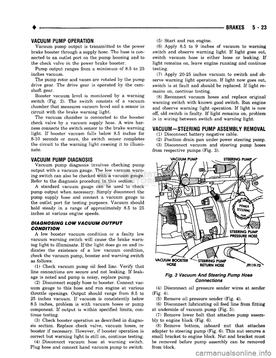
(3) Disconnect vacuum and steering pump hoses
from respective pumps (Fig. 3).
Fig.
3
Vacuum
And Steering
Pump Hose
Connections
(4) Disconnect oil pressure sender wires at sender
(Fig. 4).
(5) Remove oil pressure sender (Fig. 4).
(6) Disconnect lubricating oil feed line from fitting
at underside of vacuum pump (Fig. 5).
(7) Remove lower bolt that attaches pump assem
bly to engine block (Fig. 6).
(8) Remove bottom, inboard nut that attaches
adapter to steering pump (Fig. 6). This nut secures a
small bracket to engine block. Nut and bracket must
be removed before pump assembly can be removed from block.
Page 213 of 1502
5
- 26
BRAKES
Fig. 13 Positioning Gasket On Pump Mounting
Flange
(2) Insert pump assembly upper attaching bolt in
mounting flange and gasket. Use sealer or grease to
hold bolt in place if necessary.
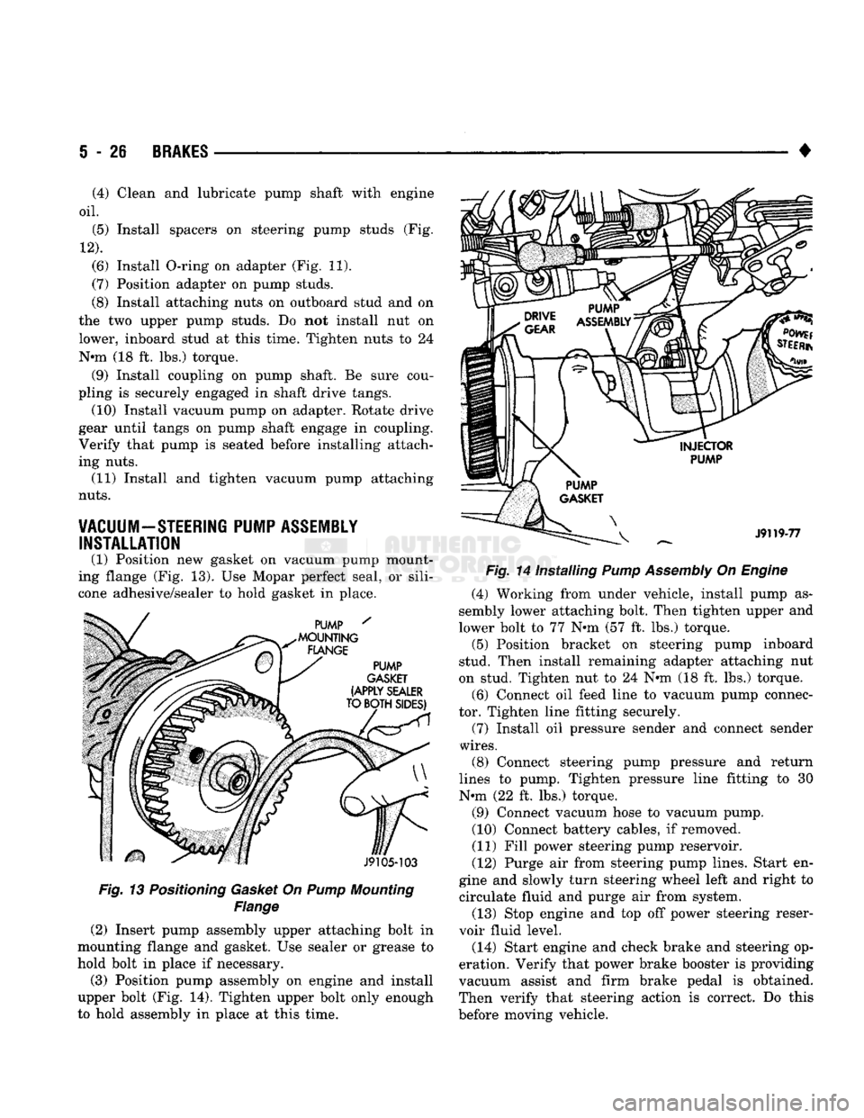
(3) Position pump assembly on engine and install
upper bolt (Fig. 14). Tighten upper bolt only enough
to hold assembly in place at this time. •
Fig. 14 Installing Pump Assembly On Engine (4) Working from under vehicle, install pump as
sembly lower attaching bolt. Then tighten upper and
lower bolt to 77 N»m (57 ft. lbs.) torque. (5) Position bracket on steering pump inboard
stud. Then install remaining adapter attaching nut
on stud. Tighten nut to 24 N«m (18 ft. lbs.) torque.
(6) Connect oil feed line to vacuum pump connec
tor. Tighten line fitting securely.
(7) Install oil pressure sender and connect sender
wires.
(8) Connect steering pump pressure and return
lines to pump. Tighten pressure line fitting to 30
N-m (22 ft. lbs.) torque.
(9) Connect vacuum hose to vacuum pump.
(10) Connect battery cables, if removed.
(11) Fill power steering pump reservoir.
(12) Purge air from steering pump lines. Start en
gine and slowly turn steering wheel left and right to circulate fluid and purge air from system.
(13) Stop engine and top off power steering reser
voir fluid level.
(14) Start engine and check brake and steering op
eration. Verify that power brake booster is providing
vacuum assist and firm brake pedal is obtained.
Then verify that steering action is correct. Do this
before moving vehicle.
(4) Clean and lubricate pump shaft with engine
oil.
(5) Install spacers on steering pump studs (Fig.
12).
(6) Install O-ring on adapter (Fig. 11).
(7) Position adapter on pump studs.
(8) Install attaching nuts on outboard stud and on
the two upper pump studs. Do not install nut on
lower, inboard stud at this time. Tighten nuts to 24
N-m (18 ft. lbs.) torque. (9) Install coupling on pump shaft. Be sure cou
pling is securely engaged in shaft drive tangs. (10) Install vacuum pump on adapter. Rotate drive
gear until tangs on pump shaft engage in coupling.
Verify that pump is seated before installing attach
ing nuts. (11) Install and tighten vacuum pump attaching
nuts.
VACUUM-STEERING PUMP ASSEMBLY INSTALLATION
(1) Position new gasket on vacuum pump mount
ing flange (Fig. 13). Use Mopar perfect seal, or sili
cone adhesive/sealer to hold gasket in place.
Page 382 of 1502
• • ^ ^ ^ INSTRUMENT PANEL AND GAUGES 8E - 1
CONTENTS
page
CLUSTER AND GAUGE SERVICE PROCEDURES . 12
CLUSTER AND GAUGE TEST PROCEDURES .. i
GENERAL INFORMATION . 1
page
MESSAGE CENTER-DIESEL ENGINE ........ 4
MESSAGE CENTER-GAS ENGINE .......... 3
SWITCH
AND PANEL COMPONENT SERVICE . 16
GENERAL
INFORMATION
INDEX
page
Generator
Indicating
System
2
Distance
Sensor
2
Electronic
Digital
Clock
3
Fuel
Level
Indicating
System
1
page
Malfunction
Indicator
(Check
Engine)
3
Oil
Pressure
Warning
Lamp
................. 2
Speedometer/Odometer
System
2
Temperature
and Oil
Indicating
System
......... 2
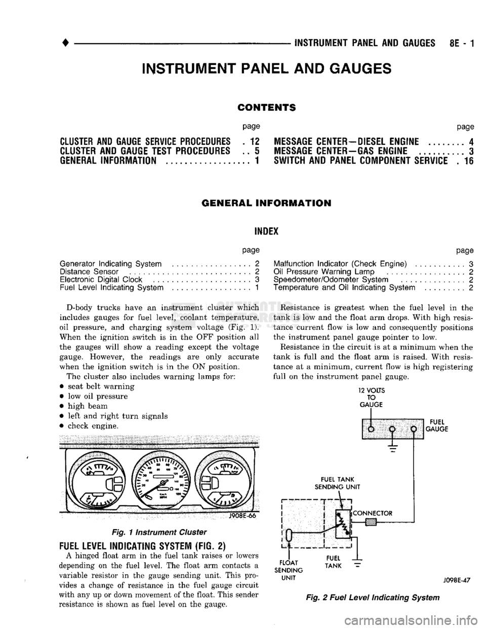
D-body trucks have an instrument cluster which
includes gauges for fuel level, coolant temperature,
oil pressure, and charging system voltage (Fig. 1).
When the ignition switch is in the OFF position all
the gauges will show a reading except the voltage gauge. However, the readings are only accurate
when the ignition switch is in the ON position.
The cluster also includes warning lamps for:
• seat belt warning
• low oil pressure
• high beam
• left and right turn signals
• check engine. J908E-66
Fig.
11nstrument
Cluster
FUEL LEVEL INDICATING SYSTEM (FIG. 2)
A hinged float arm in the fuel tank raises or lowers
depending on the fuel level. The float arm contacts a
variable resistor in the gauge sending unit. This pro
vides a change of resistance in the fuel gauge circuit
with any up or down movement of the float. This sender
resistance is shown as fuel level on the gauge. Resistance is greatest when the fuel level in the
tank is low and the float arm drops. With high resis
tance current flow is low and consequently positions
the instrument panel gauge pointer to low.
Resistance in the circuit is at a minimum when the
tank is full and the float arm is raised. With resis
tance at a minimum, current flow is high registering
full on the instrument panel gauge.
12
VOLTS
TO
GAUGE
IP
FUEL
TANK
SENDING
UNIT
FLOAT
SENDING
UNIT
1:
1
j
^
fCONNECTOR
!g|yj-»—
FUEL
GAUGE
FUEL
TANK
J098E-47
Fig.
2
Fuel
Level
Indicating
System
INSTRUMENT PANEL AND GAUGES
Page 386 of 1502
•
INSTRUMENT PANEL
AND
GAUGES
8E - 5
CLUSTER
AND
GAUGE TEST
PROCEDURES
INDEX
page
Fuel Gauge
Circuit
Test
9
Fuel Tank Sending
Unit
Test
5
Oil Pressure Gauge
Circuit
Test
..............
9
Sending
Unit
(Sensor) Test
5
page
Speedometer
10
Temperature
Gauge
Circuit
Test
8
Voltage Gauge
Circuit
Test
10
Warning Lamp System Tests
6
CAUTION:
Disconnect
battery
negative cable,
in
en
gine compartment, before servicing instrument panel. When power
is
required
for
test purposes,
connect
battery
cable
(for
test only).
Disconnect battery negative cable after test
and before continuing service procedures.
SENDING
UNIT
(SENSOR) TEST
When
a
problem occurs with
a
cluster gauge,
be
fore disassembling
the
cluster
to
check
the
gauge, check
for a
defective sending unit (sensor)
or
wiring.
(1) Sending units
and
wiring
can be
checked
by
grounding
the
connector leads,
at the
sending unit,
in
the
vehicle.
CAUTION:
When connecting
an
input
terminal
to
ground,
Do Not
leave
the
connection grounded
for
more than
a
few
seconds.
(2) With
the
ignition
in the ON
position;
a
grounded input will cause
the oil,
fuel
or
tempera
ture gauge
to
read
at or
above maximum.
FUEL TANK SENDING
UNIT
TEST
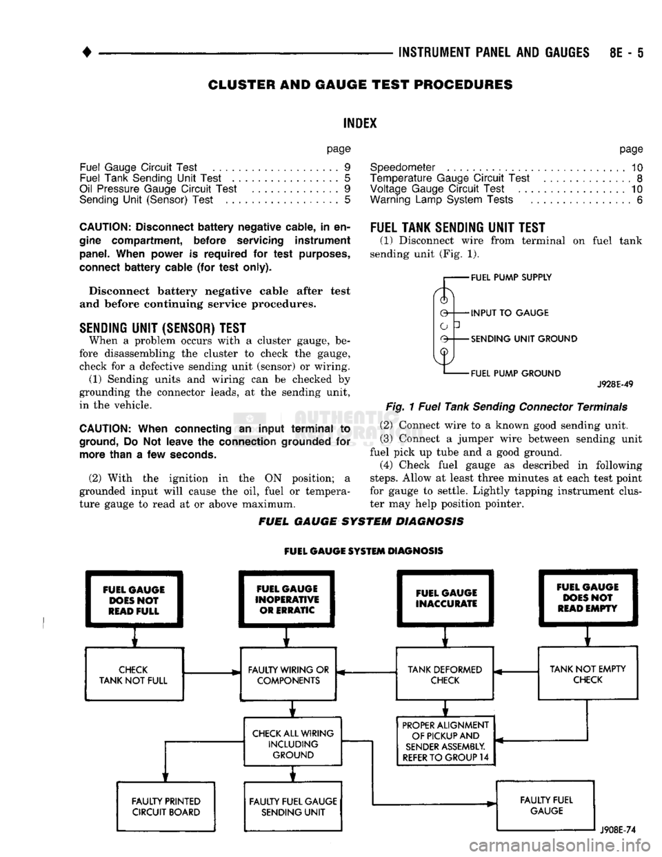
(1) Disconnect wire from terminal
on
fuel tank
sending unit (Fig.
1).
FUEL PUMP SUPPLY
INPUT
TO
GAUGE
SENDING
UNIT
GROUND
FUEL PUMP GROUND
J928E-49
Fig.
1
Fuel
Tank
Sending
Connector
Terminals
(2) Connect wire
to a
known good sending unit.
(3) Connect
a
jumper wire between sending unit
fuel pick
up
tube
and a
good ground.
(4) Check fuel gauge
as
described
in
following
steps.
Allow
at
least three minutes
at
each test point
for gauge
to
settle. Lightly tapping instrument clus
ter
may
help position pointer.
FUEL GAUGE SYSTEM DIAGNOSIS
FUEL GAUGE SYSTEM DIAGNOSIS FUEL GAUGE
DOES
NOT
READ
FULL FAULTY PRINTED
CIRCUIT BOARD FUEL GAUGE
INOPERATIVE OR ERRATIC FUEL GAUGE
INACCURATE
E
1
I
CHECK
FAULTY WIRING
OR
TANK DEFORMED
TANK
NOT
FULL COMPONENTS
CHECK
CHECK
ALL WIRING INCLUDING GROUND
i
FAULTY FUEL GAUGE SENDING
UNIT
i 1
FUEL
C
1
DOES
1
READ
1
pAUGE
I
>N0?
1
EMPTY
1
r
TANK
NOT
EMPTY
CHECK
PROPER
ALIGNMENT
OF PICKUP AND
SENDER
ASSEMBLY.
REFER
TO
GROUP
14
FAULTY FUEL
GAUGE
J908E-74
Page 757 of 1502
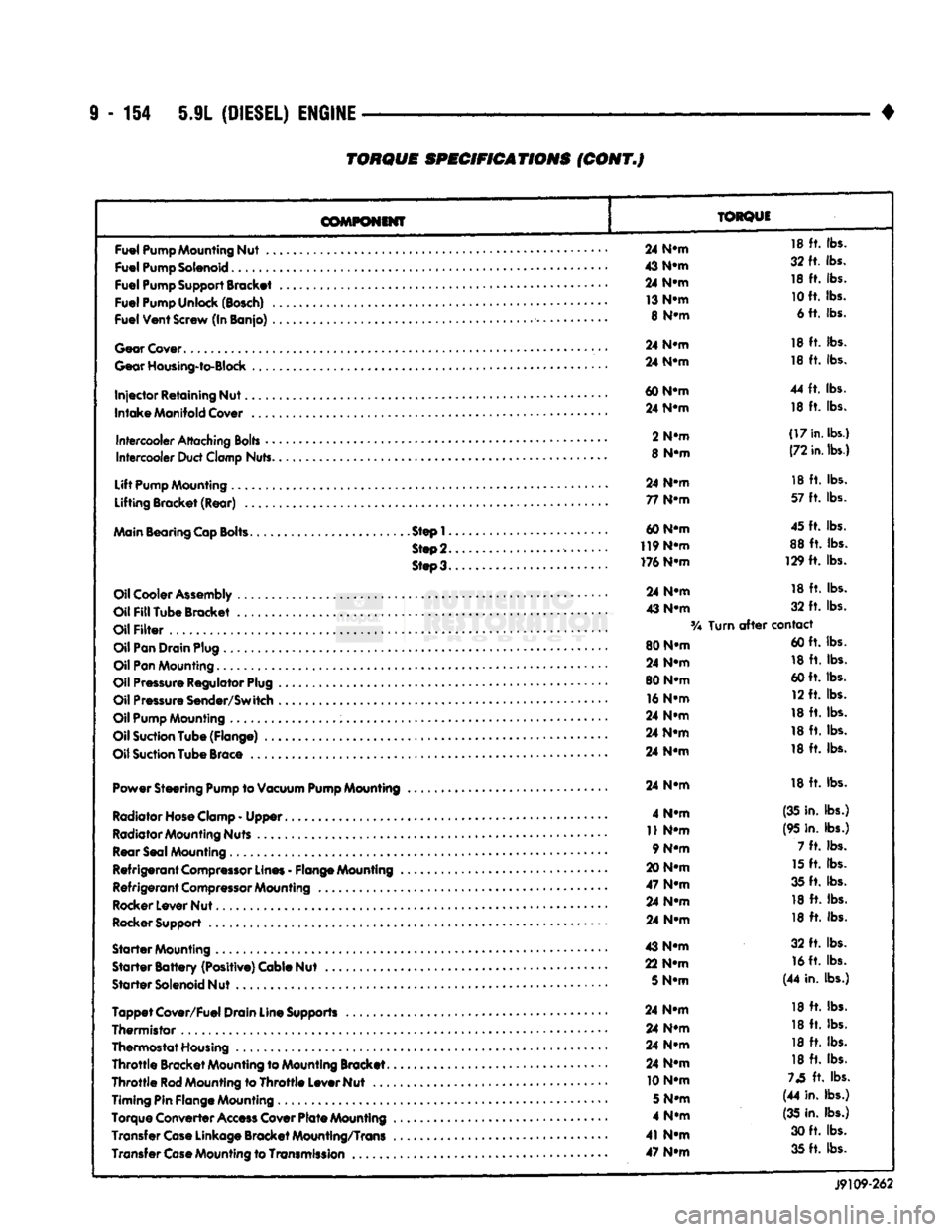
9
- 154 5.9L
(DIESEL)
ENGINE
TORQUE
SPECIFICATIONS
(CONT.J
COMPONENT
TORQUE
Fuel
Pump
Mounting
Nut
..
Fuel
Pump
Solenoid
Fuel
Pump
Support
Bracket
Fuel
Pump
Unlock
(Bosch)
.
Fuel
Vent
Screw
(In Banjo)
.
Gear
Cover
Gear
Housing-to-Block
Injector
Retaining Nut.
Intake
Manifold
Cover
Intercooler
Attaching
Bolts
•
•
Intercooler
Duct
Clamp
Nuts.
Lift
Pump
Mounting
Lifting Bracket (Rear)
..
Main
Bearing
Cap
Bolts.
Step!.
Step
2.
Steo3.
Oil
Cooler
Assembly
Oil
Fill
Tube Bracket
Oil
Filter
Oil
Pan
Drain
Plug
Oil
Pan
Mounting.........
Oil
Pressure
Regulator
Plug
Oil
Pressure
Sender/Switch
Oil
Pump
Mounting
Oil
Suction
Tube (Flange)
..
Oil
Suction
Tube
Brace
Power Steering
Pump
to
Vacuum
Pump
Mounting
Radiator Hose Clamp
-
Upper
Radiator Mounting Nuts Rear Seal Mounting
Refrigerant
Compressor
Lines
-
Flange Mounting
Refrigerant
Compressor
Mounting
Rocker Lever Nut
Rocker Support
Starter
Mounting
Starter
Battery
(Positive) Cable Nut
Starter
Solenoid Nut
Tappet
Cover/Fuel Drain Line Supports
Thermistor
,
Thermostat Housing
Throttle
Bracket Mounting to Mounting Bracket.
Throttle
Rod
Mounting to
Throttle
Lever Nut
...
Timing Pin Flange Mounting
Torque Converter
Access
Cover
Plate
Mounting
Transfer
Case
Linkage Bracket Mounting/Trans Transfer
Case
Mounting to
Transmission
..
24
N-m
18
ft.
lbs.
43
N-m
32 ft. lbs.
24
N-m
18
ft.
lbs.
13
N-m
10
ft. lbs.
8
N-m
6 ft. lbs.
24
N-m
18
ft.
lbs.
24
N-m
18
ft.
lbs.
60
N-m
44
ft.
lbs.
24
N-m
18
ft.
lbs.
2
N-m
(17
in.
lbs.)
8
N-m
(72
in.
lbs.)
24
N-m
18
ft.
lbs.
77
N-m
57
ft.
lbs.
60 N-m 45 ft. lbs.
119
N-m
88
ft.
lbs.
176 N-m 129
ft.
lbs.
24
N-m
18
ft.
lbs.
43
N-m
32
ft.
lbs.
Turn
after
contact
80 N-m 60 ft. lbs.
24
N-m
18
ft.
lbs.
80 N-m 60 ft. lbs.
16
N-m
12 ft. lbs.
24
N-m
18
ft.
lbs.
24
N-m
18
ft.
lbs.
24
N-m
18
ft.
lbs.
24
N-m
18
ft.
lbs.
4
N-m
(35 in. lbs.)
11
N-m
(95 in. lbs.)
9 N-m 7
ft.
lbs.
20
N-m
15
ft.
lbs.
47
N-m
35 ft. lbs.
24
N-m
18
ft.
lbs.
24
N-m
18
ft.
lbs.
43
N-m
32
ft.
lbs.
22
N-m
16
ft. lbs.
5
N-m
(44 in. lbs.)
24
N-m
18
ft.
lbs.
24
N-m
18
ft.
lbs.
24
N-m
18
ft.
lbs.
24
N-m
18
ft.
lbs.
10 N-m
73
ft.
lbs.
5
N-m
(44 in. lbs.)
4
N-m
(35
in. lbs.)
41
N-m
30 ft. lbs.
47
N-m
35 ft. lbs.
J9109-262
Page 973 of 1502
19
- 12
STEERING
• (5) Tighten fittings at pump and gear to 35 Nnn
(25 ft. lbs.) torque.
(6)
Install clamps on return hose on gear and
pump.
(7)
After installation, inspect and test for fluid
leaks.
PUMP REPLACEMENT—DIESEL ENGINE
REMOVAL
(1) Place a drain pan under the power steering
pump.
(2) Disconnect and cap the vacuum and steering
pump hoses.
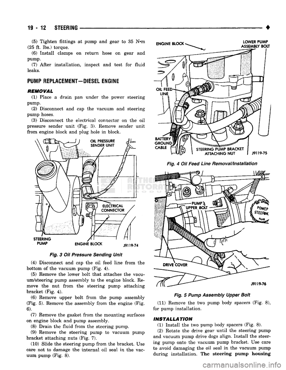
(3) Disconnect the electrical connector on the oil
pressure sender unit (Fig. 3). Remove sender unit
from engine block and plug hole in block.
PUMP ENGINE BLOCK Fig.
3 Oil
Pressure
Sending
Unit
(4) Disconnect and cap the oil feed line from the
bottom of the vacuum pump (Fig. 4). (5) Remove the lower bolt that attaches the vacu
um/steering pump assembly to the engine block. Re
move the nut from the steering pump attaching
bracket (Fig. 4).
(6)
Remove upper bolt from the pump assembly
(Fig. 5). Remove the assembly from the engine (Fig.
6).
(7) Remove the gasket from the mounting surfaces
on engine block and pump assembly.
(8) Drain the fluid from the steering pump.
(9) Remove the steering pump to vacuum pump
bracket attaching nuts (Fig. 7).
(10) Slide the steering pump from the bracket. Use
care not to damage the internal oil seal in the vac uum pump (Fig. 8).
Fig.
4 Oil
Feed
Line
Removal/Installation
Fig.
5
Pump
Assembly
Upper
Bolt
(11) Remove the two pump body spacers (Fig. 8),
for pump installation.
INSTALLATION (1) Install the two pump body spacers (Fig. 8).
(2) Rotate the drive gear until the steering pump
and vacuum pump drive dogs align. Install the steer
ing pump onto the vacuum pump bracket. Use care
to avoid damaging the oil seal in the vacuum pump during installation. The steering pump housing