1993 DODGE TRUCK jump start terminals
[x] Cancel search: jump start terminalsPage 29 of 1502
0-10
LUBRICATION
AND
MAINTENANCE
•
O.K.TO
JUMP
START BATTERY
CONDITION
INDICATOR DO NOT
JUMP
START J9100-26 DARKENED
INDICATOR
WITH
GREEN
DOT
•
LETTERS
Uk-
FLUID
Lt- E:L .
DARKENED
INDICATOR
NO
GREEN
DOT •
BATTERY CHARGE
10'//
• Ft UID
L
EVEl
OK
LIGHT
OR
BRIGHT
INDICATOR
•
RAT-cci,
C
H
A
P
C;
F
R^'^Owh
AM.w-GE
FlAf StIll BE
r-
•
!
F-
r tjr r
?
STA
F
•
r
O U n
C
AI:
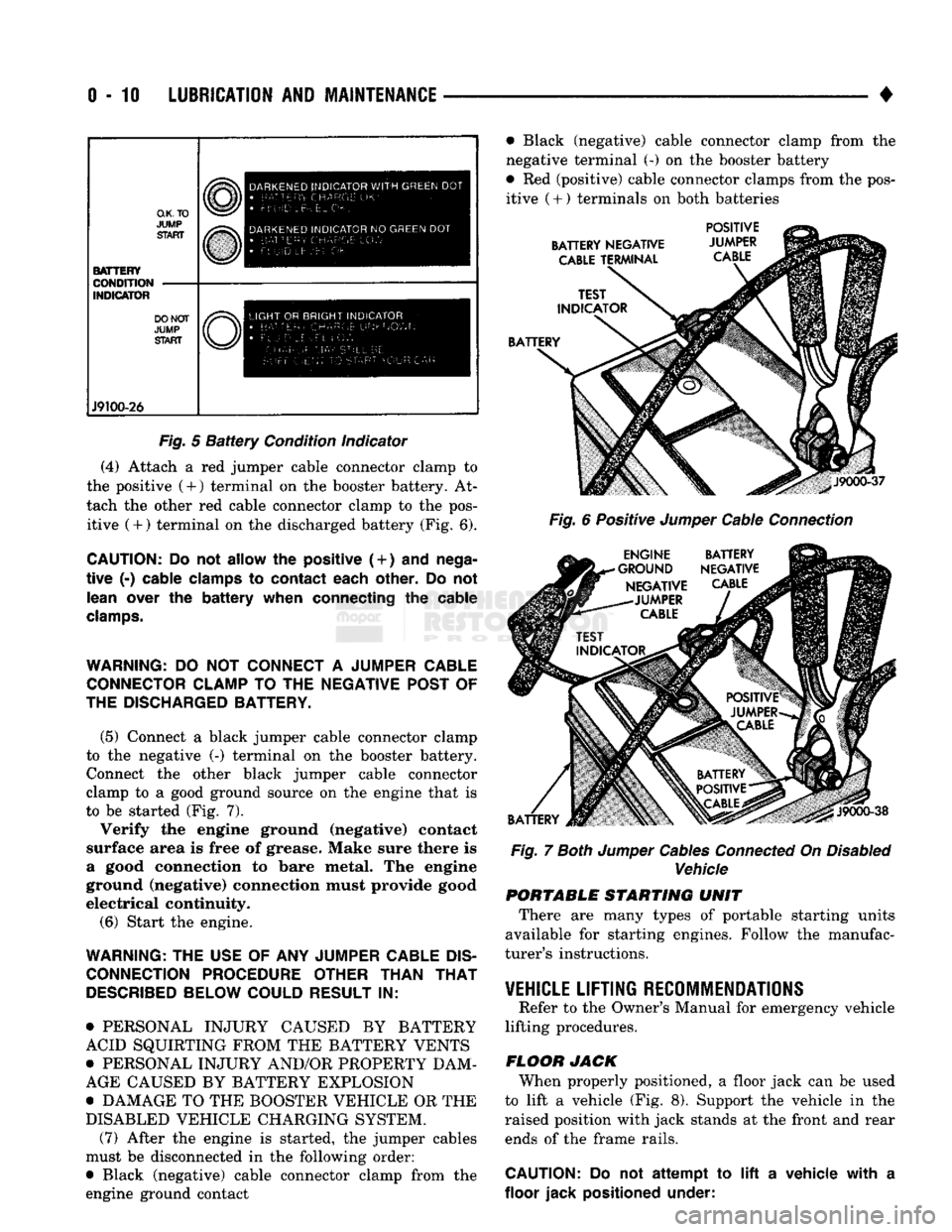
Fig.
5
Battery
Condition indicator
(4) Attach a red jumper cable connector clamp to
the positive (4-) terminal on the booster battery. At
tach the other red cable connector clamp to the pos itive (+) terminal on the discharged battery (Fig. 6).
CAUTION:
Do not
allow
the
positive (
+
)
and
nega
tive
(-)
cable clamps
to
contact each other.
Do not
lean over
the
battery when connecting
the
cable
clamps.
WARNING:
DO NOT
CONNECT
A
JUMPER CABLE CONNECTOR CLAMP
TO THE
NEGATIVE POST
OF
THE DISCHARGED BATTERY.
(5) Connect a black jumper cable connector clamp
to the negative (-) terminal on the booster battery. Connect the other black jumper cable connector
clamp to a good ground source on the engine that is
to be started (Fig. 7).
Verify the engine ground (negative) contact
surface area is free of grease. Make sure there is
a good connection to bare metal. The engine
ground (negative) connection must provide good
electrical continuity.
(6) Start the engine.
WARNING:
THE
USE
OF ANY
JUMPER CABLE
DIS
CONNECTION PROCEDURE OTHER THAN
THAT
DESCRIBED
BELOW COULD RESULT
IN:
• PERSONAL INJURY CAUSED BY BATTERY
ACID SQUIRTING FROM THE BATTERY VENTS
• PERSONAL INJURY AND/OR PROPERTY DAM
AGE CAUSED BY BATTERY EXPLOSION
• DAMAGE TO THE BOOSTER VEHICLE OR THE
DISABLED VEHICLE CHARGING SYSTEM. (7) After the engine is started, the jumper cables
must be disconnected in the following order:
• Black (negative) cable connector clamp from the
engine ground contact • Black (negative) cable connector clamp from the
negative terminal (-) on the booster battery
• Red (positive) cable connector clamps from the pos itive
(
+ ) terminals on both batteries
BATTERY NEGATIVE
CABLE
TERMINAL POSITIVE
JUMPER
CABLE
BATTERY
J9000-37
Fig.
6 Positive
Jumper
Cable
Connection
ENGINE BATTERY
•GROUND NEGATIVE NEGATIVE
CABLE
-JUMPER
CABLE
BATTERY
J9000-38
Fig.
7
Both
Jumper
Cables
Connected
On
Disabled
Vehicle PORTABLE STARTING UNIT
There are many types of portable starting units
available for starting engines. Follow the manufac
turer's instructions.
VEHICLE
LIFTING RECOMMENDATIONS
Refer to the Owner's Manual for emergency vehicle
lifting procedures.
FLOOR JACK When properly positioned, a floor jack can be used
to lift a vehicle (Fig. 8). Support the vehicle in the
raised position with jack stands at the front and rear ends of the frame rails.
CAUTION:
Do not
attempt
to lift a
vehicle with
a
floor jack positioned under:
Page 334 of 1502
•
ELECTRICAL
8A - 13 GENERATOR TEST PROCEDURES ON
VEHICLE
INDEX
page
Current
Output
Test
......................
14
Diagnostic Procedures
13
General
Information
13
Generator
Output
Wire Resistance Test
.......
13
page
How
to
Use
Malfunction
Indicator
(Check Engine) Lamp
for
Fault
Codes
17
Operational Check
with
Voltmeter
............
13
Using
On-Board Diagnostic System
15
GENERAL
INFORMATION
The generator
is
belt-driven
by the
engine.
All en
gines
use
serpentine drive. The amount
of DC
current produced
by the
gener
ator
is
controlled
by the
Powertrain Control Module (PCM).
All vehicles
are
equipped with
On
Board Diagnos
tics (OBD).
All OBD
sensing systems
are
monitored
by
the PCM. The PCM
will store
in
electronic mem ory
any
detectable failure within
the
monitored cir
cuits.
Refer
to
USING ON-BOARD DIAGNOSTIC SYSTEM
in
this group
for
more information.
OPERATIONAL CHECK
WITH
VOLTMETER
When
the
ignition switch
is
turned
to the RUN po
sition, battery potential will register
on the
voltme
ter. During engine cranking
a
lower voltage will appear
on the
meter. With
the
engine running,
a
voltage reading higher than
the
first reading (igni
tion
in RUN)
should register.
DIAGNOSTIC PROCEDURES
If
the
indicator does
not
operate properly,
or if an
undercharged
or
overcharged battery condition
oc
curs,
the
following procedures
may be
used
to
diag
nose
the
charging system. Remember that
an
undercharged battery
is
often
caused
by:
• accessories being left
on
overnight
•
or by a
defective switch which allows
a
bulb, such
as a
trunk
or
glove
box
light,
to
stay
on
(refer
to
Ignition
Off
Draw).
WISUAL
INSPECTION
• Inspect condition
of
battery cable terminals, bat
tery posts, connections
at
engine block, starter motor solenoid
and
relay. They should
be
clean
and
tight.
Repair
as
required.
• Inspect
all
fuses
in the
fuse block
for
tightness
in
receptacles. They should
be
properly installed
and
tight. Repair
or
replace
as
required.
• Inspect generator mounting bolts
for
tightness.
Re
place
or
torque bolt
as
required (refer
to
Torque Specifications).
• Inspect generator drive belt condition
and
tension.
Tension
or
replace belt
as
required. Refer
to
Belt
Tension Specifications. • Inspect connection
at
generator
B+
output.
It
should
be
clean
and
tight. Repair
as
required.
GENERATOR
OUTPUT
WIRE RESISTANCE TEST
(FIG.
1)
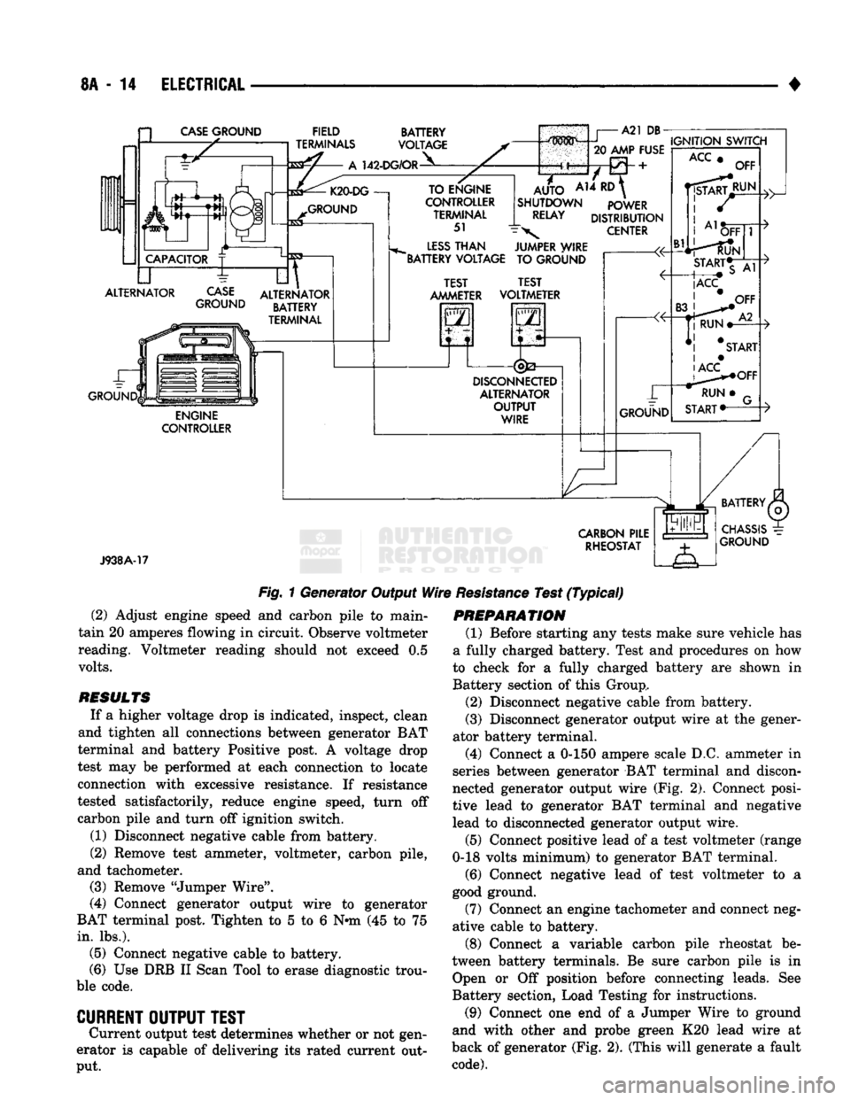
Generator output wire resistance test will show
amount
of
voltage drop across generator output wire
between generator
BAT
terminal
and
battery posi tive post.
PREPARATION
(1) Before starting test make sure vehicle
has a
fully charged battery. Test
and
procedures
on how to
check
for a
fully charged battery
are
shown
in
Bat
tery section
of
this Group.
(2) Turn
OFF
ignition switch.
(3)
Disconnect negative cable from battery.
(4)
Disconnect generator output wire from genera
tor output Battery terminal. (5) Connect
a 0-150
ampere scale
D.C.
ammeter
in
series between generator
BAT
terminal
and
discon
nected generator output wire. Connect Positive lead
to generator
BAT
terminal
and
Negative lead
to
dis connected generator output wire. (6) Connect Positive lead
of a
test voltmeter
(Range
0-18
volts minimum)
to
disconnected genera
tor output wire. Connect negative lead
of
test voltme
ter
to
battery positive cable
at
positive post. (7) Connect
one end of a
Jumper Wire
to
ground
and with other
end
probe green
K20
lead wire
at
back
of
generator
(Fig. 1).
(This will generate
a
fault
code).
CAUTION:
Do not
connect blue
A142
lead
of
wiring
to ground. Refer
to
Group
8W
-
Wiring Diagrams
for
more information.
(8) Connect
an
engine tachometer
and
connect neg
ative cable
to
battery.
(9) Connect
a
variable carbon pile rheostat
be
tween battery terminals.
Be
sure carbon pile
is in
"Open"
or "Off
position before connecting leads.
See
Battery Section, Load Testing
for
instructions.
TEST
(1) Start engine. Immediately after starting,
re
duce engine speed
to
idle.
Page 335 of 1502
8A
- 14
ELECTRICAL
CASE
GROUND
FIELD
TERMINALS
142-DG/OR
BATTERY
VOLTAGE
ALTERNATOR
CASE
GROUND
GROUND ALTERNATOR
BATTERY
TERMINAL
ENGINE
CONTROLLER TO ENGINE
CONTROLLER TERMINAL
51
LESS
THAN
"BATTERY VOLTAGE
m^mm i
A21 DB-
20
AMP FUSE
A14
RD
AUTO
SHUTDOWN
RELAY
IGNITION
SWITCH
POWER
DISTRIBUTION
CENTER
JUMPER WIRE TO GROUND TEST
AMMETER TEST
VOLTMETER
2
i
DISCONNEaED
ALTERNATOR
OUTPUT
WIRE
ACC
OFF
J938A-17
CARBON
PILE
RHEOSTAT
Fig.
1 Generator Output
Wire
Resistance
Test
(Typical)
(2) Adjust engine speed and carbon pile to main
tain 20 amperes flowing in circuit. Observe voltmeter
reading. Voltmeter reading should not exceed 0.5
volts.
RESULTS
If a higher voltage drop is indicated, inspect, clean
and tighten all connections between generator BAT
terminal and battery Positive post. A voltage drop
test may be performed at each connection to locate
connection with excessive resistance. If resistance
tested satisfactorily, reduce engine speed, turn off carbon pile and turn off ignition switch.
(1) Disconnect negative cable from battery.
(2) Remove test ammeter, voltmeter, carbon pile,
and tachometer. (3) Remove "Jumper Wire".
(4) Connect generator output wire to generator
BAT terminal post. Tighten to 5 to 6 Nnn (45 to 75
in.
lbs.). (5) Connect negative cable to battery.
(6) Use DRB II Scan Tool to erase diagnostic trou
ble code.
CURRENT
OUTPUT
TEST
Current output test determines whether or not gen
erator is capable of delivering its rated current out
put.
PREPARATION
(1) Before starting any tests make sure vehicle has
a fully charged battery. Test and procedures on how
to check for a fully charged battery are shown in
Battery section of this Group,
(2) Disconnect negative cable from battery.
(3) Disconnect generator output wire at the gener
ator battery terminal.
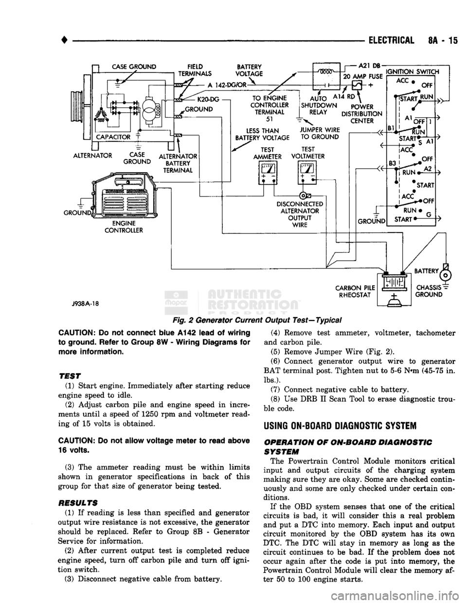
(4) Connect a 0-150 ampere scale D.C. ammeter in
series between generator BAT terminal and discon
nected generator output wire (Fig. 2). Connect posi
tive lead to generator BAT terminal and negative
lead to disconnected generator output wire.
(5) Connect positive lead of a test voltmeter (range
0-18 volts minimum) to generator BAT terminal.
(6) Connect negative lead of test voltmeter to a
good ground.
(7) Connect an engine tachometer and connect neg
ative cable to battery.
(8) Connect a variable carbon pile rheostat be
tween battery terminals. Be sure carbon pile is in Open or Off position before connecting leads. See
Battery section, Load Testing for instructions.
(9) Connect one end of a Jumper Wire to ground
and with other and probe green K20 lead wire at
back of generator (Fig. 2). (This will generate a fault
code).
Page 336 of 1502
•
ELECTRICAL
8A - 15 a
CASE
GROUND
CAPACITOR
ALTERNATOR ~L FIELD
TERMINALS
A
142-DG/OR BATTERY
VOLTAGE K20-DG
—!
GROUND
CASE
GROUND
til
ALTERNATOR BATTERY
TERMINAL ENGINE
CONTROLLER TO ENGINE
CONTROLLER TERMINAL
51
LESS
THAN
BATTERY VOLTAGE A21
DB-
.....
IGNITION SWITCH
20 AMP FUSE
AUTO
AH ^
SHUTDOWN POWER
RELAY
DISTRIBUTION
\
CENTER TEST
AMMETER JUMPER WIRE
TO GROUND
TEST
VOLTMETER
GO
5—n
DISCONNECTED
ALTERNATOR OUTPUT WIRE GROUND
ACC
Bl
OFF
RUN OFF
START*T
|ACC
CARBON
PILE RHEOSTAT
J938A-18
Fig.
2 Generator Current Output Test—Typical
CAUTION:
Do not
connect
blue
A142
lead
of
wiring
to ground.
Refer
to
Group
8W -
Wiring
Diagrams
for
more
information.
TEST
(1) Start engine. Immediately after starting reduce
engine speed to idle. (2) Adjust carbon pile and engine speed in incre
ments until a speed of 1250 rpm and voltmeter read
ing of 15 volts is obtained.
CAUTION:
Do not
allow
voltage
meter
to
read
above
16 volts.
(3) The ammeter reading must be within limits
shown in generator specifications in back of this
group for that size of generator being tested.
RESULTS
(1) If reading is less than specified and generator
output wire resistance is not excessive, the generator
should be replaced. Refer to Group 8B - Generator
Service for information.
(2) After current output test is completed reduce
engine speed, turn off carbon pile and turn off igni
tion switch.
(3) Disconnect negative cable from battery. (4) Remove test ammeter, voltmeter, tachometer
and carbon pile. (5) Remove Jumper Wire (Fig. 2).
(6) Connect generator output wire to generator
BAT terminal post. Tighten nut to 5-6 Nnn (45-75 in.
lbs.).
(7) Connect negative cable to battery.
(8) Use DRB II Scan Tool to erase diagnostic trou
ble code.
USING
ON-BOARD
DIAGNOSTIC
SYSTEM
OPERATION
OF
ON-BOARD
DIAGNOSTIC
SYSTEM
The Powertrain Control Module monitors critical
input and output circuits of the charging system
making sure they are okay. Some are checked contin
uously and some are only checked under certain con
ditions.
If the OBD system senses that one of the critical
circuits is bad, it will consider this a real problem
and put a DTC into memory. Each input and output
circuit monitored by the OBD system has its own
DTC.
The DTC will stay in memory as long as the
circuit continues to be bad. If the problem does not
occur again after the code is put into memory, the
Powertrain Control Module will clear the memory af
ter 50 to 100 engine starts.
Page 362 of 1502
*
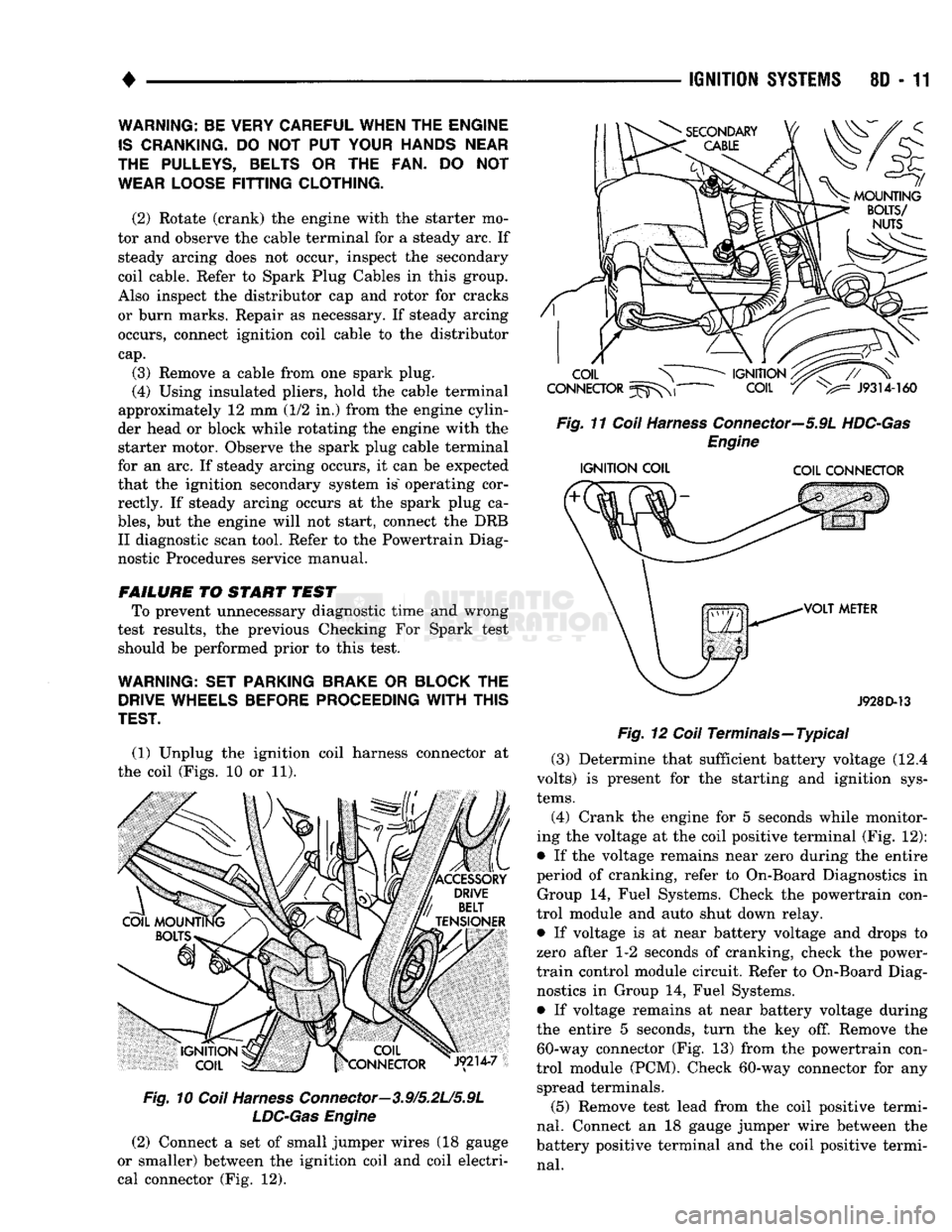
(1) Unplug the ignition coil harness connector at
the coil (Figs. 10 or 11).
Fig.
10
Coil
Harness
Connector—3.9/5.2L/5.9L
LDC-Gas
Engine
(2) Connect a set of small jumper wires (18 gauge
or smaller) between the ignition coil and coil electri
cal connector (Fig. 12).
IGNITION
SYSTEMS
80 - 11
Fig.
11
Coil
Harness
Connector—5.9L
HDC-Gas
Engine
IGNITION
COIL COIL CONNECTOR
J928D-13
Fig.
12
Coil
Terminals—Typical (3) Determine that sufficient battery voltage (12.4
volts) is present for the starting and ignition sys
tems.
(4) Crank the engine for 5 seconds while monitor
ing the voltage at the coil positive terminal (Fig. 12):
• If the voltage remains near zero during the entire
period of cranking, refer to On-Board Diagnostics in Group 14, Fuel Systems. Check the powertrain con
trol module and auto shut down relay.
• If voltage is at near battery voltage and drops to
zero after 1-2 seconds of cranking, check the power-
train control module circuit. Refer to On-Board Diag nostics in Group 14, Fuel Systems.
• If voltage remains at near battery voltage during
the entire 5 seconds, turn the key off. Remove the 60-way connector (Fig. 13) from the powertrain con
trol module (PCM). Check 60-way connector for any spread terminals.
(5) Remove test lead from the coil positive termi
nal.
Connect an 18 gauge jumper wire between the
battery positive terminal and the coil positive termi
nal.
WARNING: BE VERY CAREFUL WHEN THE ENGINE
IS
CRANKING.
DO NOT PUT
YOUR HANDS NEAR
THE PULLEYS, BELTS
OR THE FAN. DO NOT
WEAR LOOSE
FITTING
CLOTHING.
(2) Rotate (crank) the engine with the starter mo
tor and observe the cable terminal for a steady arc. If steady arcing does not occur, inspect the secondary
coil cable. Refer to Spark Plug Cables in this group.
Also inspect the distributor cap and rotor for cracks
or burn marks. Repair as necessary. If steady arcing occurs, connect ignition coil cable to the distributor
cap.
(3) Remove a cable from one spark plug.
(4) Using insulated pliers, hold the cable terminal
approximately 12 mm (1/2 in.) from the engine cylin
der head or block while rotating the engine with the starter motor. Observe the spark plug cable terminal
for an arc. If steady arcing occurs, it can be expected
that the ignition secondary system is" operating cor rectly. If steady arcing occurs at the spark plug ca
bles,
but the engine will not start, connect the DRB II diagnostic scan tool. Refer to the Powertrain Diag
nostic Procedures service manual.
FAILURE
TO START TEST To prevent unnecessary diagnostic time and wrong
test results, the previous Checking For Spark test should be performed prior to this test.
WARNING: SET PARKING BRAKE
OR
BLOCK
THE
DRIVE WHEELS BEFORE PROCEEDING
WITH
THIS
TEST.
Page 387 of 1502
8E
- 6
INSTRUMENT PANEL
AND
GAUGES
•
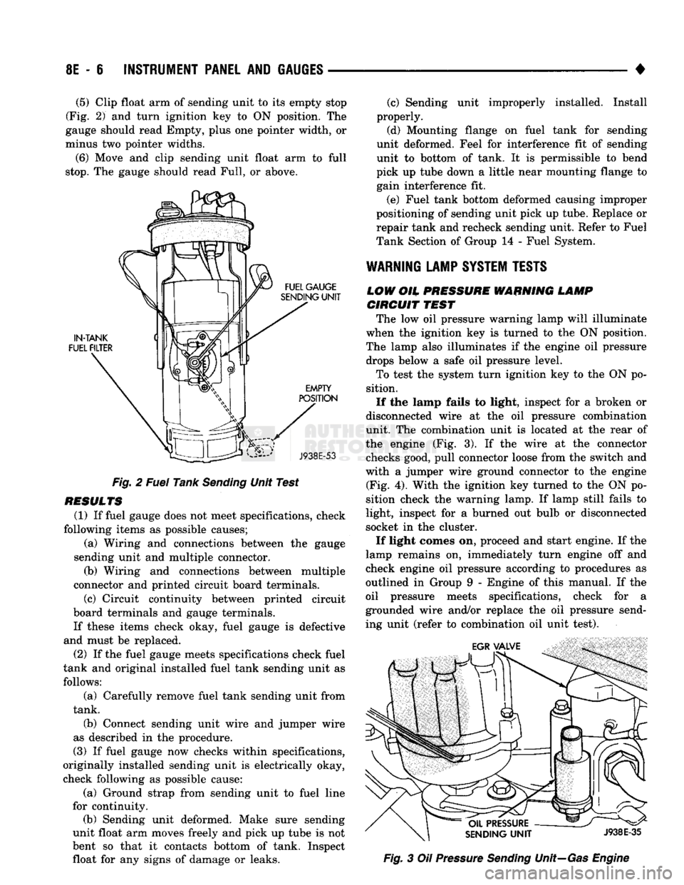
(5)
Clip float arm of sending unit to its empty stop
(Fig. 2) and turn ignition key to ON position. The
gauge should read Empty, plus one pointer width, or
minus two pointer widths.
(6) Move and clip sending unit float arm to full
stop.
The gauge should read Full, or above.
Fig. 2 Fuel Tank Sending Unit Test
RESULTS (1) If fuel gauge does not meet specifications, check
following items as possible causes; (a) Wiring and connections between the gauge
sending unit and multiple connector. (b) Wiring and connections between multiple
connector and printed circuit board terminals.
(c) Circuit continuity between printed circuit
board terminals and gauge terminals.
If these items check okay, fuel gauge is defective
and must be replaced.
(2) If the fuel gauge meets specifications check fuel
tank and original installed fuel tank sending unit as follows:
(a) Carefully remove fuel tank sending unit from
tank.
(b) Connect sending unit wire and jumper wire
as described in the procedure.
(3) If fuel gauge now checks within specifications,
originally installed sending unit is electrically okay,
check following as possible cause:
(a) Ground strap from sending unit to fuel line
for continuity. (b) Sending unit deformed. Make sure sending
unit float arm moves freely and pick up tube is not
bent so that it contacts bottom of tank. Inspect float for any signs of damage or leaks. (c) Sending unit improperly installed. Install
properly.
(d) Mounting flange on fuel tank for sending
unit deformed. Feel for interference fit of sending
unit to bottom of tank. It is permissible to bend
pick up tube down a little near mounting flange to gain interference fit.
(e) Fuel tank bottom deformed causing improper
positioning of sending unit pick up tube. Replace or
repair tank and recheck sending unit. Refer to Fuel
Tank Section of Group 14 - Fuel System.
WARNING
LAMP
SYSTEM
TESTS
LOW
OH.
PRESSURE WARNING LAMP CIRCUIT
TEST
The low oil pressure warning lamp will illuminate
when the ignition key is turned to the ON position.
The lamp also illuminates if the engine oil pressure drops below a safe oil pressure level.
To test the system turn ignition key to the ON po
sition.
If the lamp fails to light, inspect for a broken or
disconnected wire at the oil pressure combination
unit. The combination unit is located at the rear of
the engine (Fig. 3). If the wire at the connector checks good, pull connector loose from the switch and
with a jumper wire ground connector to the engine (Fig. 4). With the ignition key turned to the ON po
sition check the warning lamp. If lamp still fails to
light, inspect for a burned out bulb or disconnected
socket in the cluster.
If light comes on, proceed and start engine. If the
lamp remains on, immediately turn engine off and
check engine oil pressure according to procedures as
outlined in Group 9 - Engine of this manual. If the
oil pressure meets specifications, check for a
grounded wire and/or replace the oil pressure send
ing unit (refer to combination oil unit test). Fig. 3 Oil Pressure Sending Unit—Gas Engine
Page 875 of 1502
14
- 56
FUEL
SYSTEM
• (5) Move the switch to the HIGH position. The en
gine speed should increase. Move the switch to the
LOW position. The engine speed should decrease.
(a) If the engine speed changes while using the
exerciser tool, the IAC motor is functioning prop
erly. Disconnect the exerciser tool and connect the
IAC stepper motor wire connector to the stepper motor.
(b) If the engine speed does not change, turn the
ignition OFF and proceed to step (6). Do not discon
nect exerciser from the IAC stepper motor.
(6) Remove the IAC stepper motor from the throt
tle body.
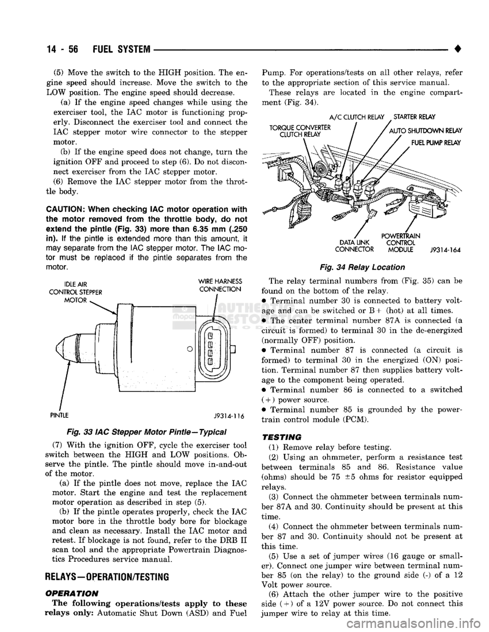
CAUTION:
When checking IAC motor operation with
the motor removed from
the
throttle
body,
do not
extend
the
pintle (Fig.
33)
more than
6.35 mm (.250
in).
If the pintle is
extended more than
this
amount,
it
may
separate
from
the
IAC stepper
motor.
The
IAC
mo
tor
must
be
replaced
if the pintle
separates
from
the
motor.
WIRE HARNESS
PINTLE
J9314-116
Fig.
33 IAC Stepper Motor Pintle—Typical (7) With the ignition OFF, cycle the exerciser tool
switch between the HIGH and LOW positions. Ob
serve the pintle. The pintle should move in-and-out
of the motor.
(a) If the pintle does not move, replace the IAC
motor. Start the engine and test the replacement
motor operation as described in step (5). (b) If the pintle operates properly, check the IAC
motor bore in the throttle body bore for blockage and clean as necessary. Install the IAC motor and
retest. If blockage is not found, refer to the DRB II scan tool and the appropriate Powertrain Diagnos
tics Procedures service manual.
RELAYS—OPERATION/TESTING
OPERATION
The following operations/tests apply to these
relays only: Automatic Shut Down (ASD) and Fuel Pump. For operations/tests on all other relays, refer
to the appropriate section of this service manual.
These relays are located in the engine compart
ment (Fig. 34).
DATA LINK CONTROL
CONNECTOR MODULE
J9314-164
Fig.
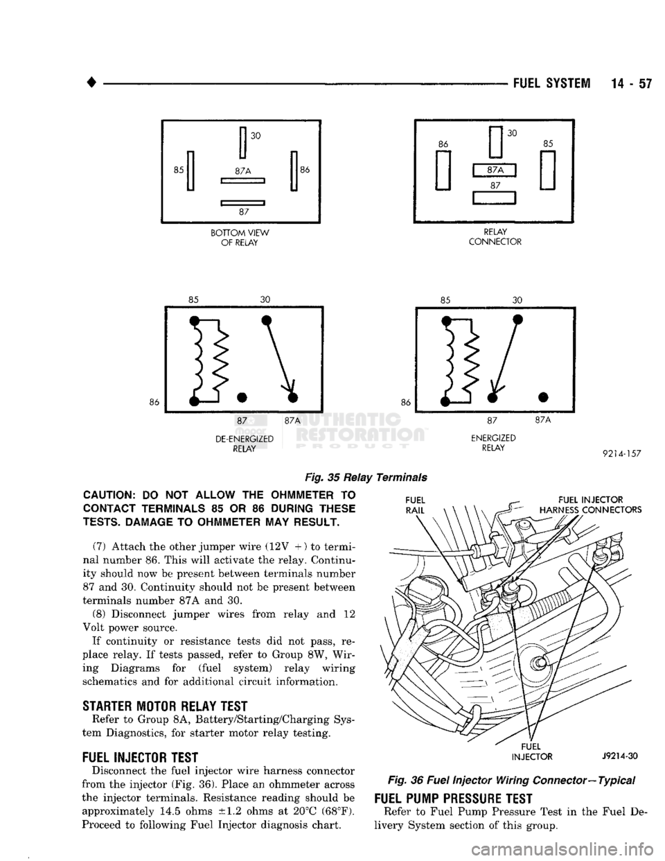
34 Relay Location The relay terminal numbers from (Fig. 35) can be
found on the bottom of the relay. • Terminal number 30 is connected to battery volt
age and can be switched or B+ (hot) at all times.
• The center terminal number 87A is connected (a
circuit is formed) to terminal 30 in the de-energized (normally OFF) position.
• Terminal number 87 is connected (a circuit is
formed) to terminal 30 in the energized (ON) posi
tion. Terminal number 87 then supplies battery volt age to the component being operated.
• Terminal number 86 is connected to a switched ( +
)
power source.
• Terminal number 85 is grounded by the power-
train control module (PCM).
TESTING
(1) Remove relay before testing. (2) Using an ohmmeter, perform a resistance test
between terminals 85 and 86. Resistance value (ohms) should be 75 ±5 ohms for resistor equipped
relays.
(3) Connect the ohmmeter between terminals num
ber 87A and 30. Continuity should be present at this
time.
(4) Connect the ohmmeter between terminals num
ber 87 and 30. Continuity should not be present at
this time.
(5) Use a set of jumper wires (16 gauge or small
er).
Connect one jumper wire between terminal num
ber 85 (on the relay) to the ground side (-) of a 12 Volt power source. (6) Attach the other jumper wire to the positive
side ( +
)
of a 12V power source. Do not connect this
jumper wire to relay at this time.
Page 876 of 1502
•
BOTTOM
VIEW
OF RELAY RELAY
CONNECTOR
DE-ENERGIZED
RELAY
ENERGIZED
RELAY
9214-157
Fig.
35 Relay Terminals
CAUTION:
DO NOT
ALLOW
THE
OHMMETER
TO
CONTACT TERMINALS
85 OR 86
DURING THESE
TESTS.
DAMAGE
TO
OHMMETER
MAY
RESULT.
(7) Attach the other jumper wire (12V +) to termi
nal number 86. This will activate the relay. Continu
ity should now be present between terminals number
87 and 30. Continuity should not be present between
terminals number 87A and 30.
(8) Disconnect jumper wires from relay and 12
Volt power source.
If continuity or resistance tests did not pass, re
place relay. If tests passed, refer to Group 8W, Wir ing Diagrams for (fuel system) relay wiring schematics and for additional circuit information.
STARTER
MOTOR RELAY TEST
Refer to Group 8A, Battery/Starting/Charging Sys
tem Diagnostics, for starter motor relay testing.
FUEL INJECTOR TEST
Disconnect the fuel injector wire harness connector
from the injector (Fig. 36). Place an ohmmeter across
the injector terminals. Resistance reading should be approximately 14.5 ohms ±1.2 ohms at 20°C (68°F).
Proceed to following Fuel Injector diagnosis chart.
FUEL INJECTOR
HARNESS
CONNECTORS
FUEL
INJECTOR
J9214-30
Fig.
36
Fuel
Injector Wiring
Connector—
Typical
FUEL PUMP
PRESSURE
TEST
Refer to Fuel Pump Pressure Test in the Fuel De
livery System section of this group.