1993 DODGE TRUCK dead battery
[x] Cancel search: dead batteryPage 371 of 1502
8D
- 20
IGNITION
SYSTEMS
•
ENGINE
COOLANT
TEMPERATURE
SENSOR
WARNING: HOT, PRESSURIZED COOLANT CAN CAUSE INJURY BY SCALDING. COOLING SYSTEM MUST BE PARTIALLY DRAINED BEFORE REMOV
ING THE COOLANT TEMPERATURE SENSOR. RE
FER TO GROUP 7, COOLING.
REMOVAL
(1) Partially drain cooling system. Refer to Group
7, Cooling.
(2)
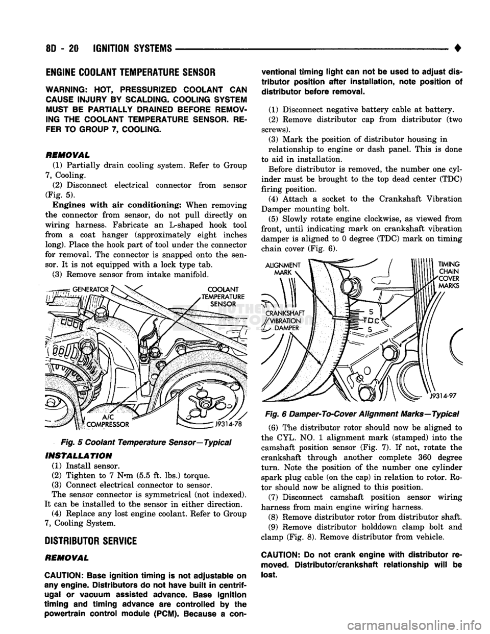
Disconnect electrical connector from sensor
(Fig. 5). Engines with air conditioning: When removing
the connector from sensor, do not pull directly on
wiring harness. Fabricate an L-shaped hook tool
from a coat hanger (approximately eight inches
long).
Place the hook part of tool under the connector
for removal. The connector is snapped onto the sen sor. It is not equipped with a lock type tab.
(3) Remove sensor from intake manifold.
Fig. 5 Coolant Temperature
Sensor—
Typical
INSTALLATION
(1) Install sensor.
(2) Tighten to 7 Nnn (5.5 ft. lbs.) torque.
(3) Connect electrical connector to sensor.
The sensor connector is symmetrical (not indexed).
It can be installed to the sensor in either direction. (4) Replace any lost engine coolant. Refer to Group
7, Cooling System.
DISTRIBUTOR
SERVICE
REMOVAL
CAUTION:
Base
ignition timing
is not
adjustable
on
any
engine. Distributors
do not
have
built
in
centrif
ugal
or
vacuum assisted advance.
Base
ignition
timing
and
timing advance
are
controlled
by the
powertrain control module
(PCM).
Because
a
con
ventional timing light can
not be
used
to
adjust
dis
tributor
position
after
installation, note position
of
distributor before removal.
(1) Disconnect negative battery cable at battery.
(2) Remove distributor cap from distributor (two
screws).
(3) Mark the position of distributor housing in
relationship to engine or dash panel. This is done
to aid in installation. Before distributor is removed, the number one cyl
inder must be brought to the top dead center (TDC)
firing position. (4) Attach a socket to the Crankshaft Vibration
Damper mounting bolt.
(5) Slowly rotate engine clockwise, as viewed from
front, until indicating mark on crankshaft vibration damper is aligned to 0 degree (TDC) mark on timing
chain cover (Fig. 6).
Fig. 6 Damper-To-Cover Alignment Marks—Typical (6) The distributor rotor should now be aligned to
the CYL. NO. 1 alignment mark (stamped) into the camshaft position sensor (Fig. 7). If not, rotate the
crankshaft through another complete 360 degree
turn.
Note the position of the number one cylinder spark plug cable (on the cap) in relation to rotor. Ro
tor should now be aligned to this position.
(7) Disconnect camshaft position sensor wiring
harness from main engine wiring harness.
(8) Remove distributor rotor from distributor shaft. (9) Remove distributor holddown clamp bolt and
clamp (Fig. 8). Remove distributor from vehicle.
CAUTION: Do not
crank engine
with
distributor
re
moved.
Distributor/crankshaft relationship
will
be
lost.
Page 663 of 1502
CAUTION:
Th© plunger and
tappet
bodies are not
interchangeable. The plunger and valve must al
ways
be
fitted
to the
original
body. It is advisable to
work
on one
tappet
at a
time
to avoid
mixing
of parts. Mixed
parts
are not
compatible.
DO NOT
dis
assemble
a
tappet
on a
dirty
work
bench,
DISASSEMBLE
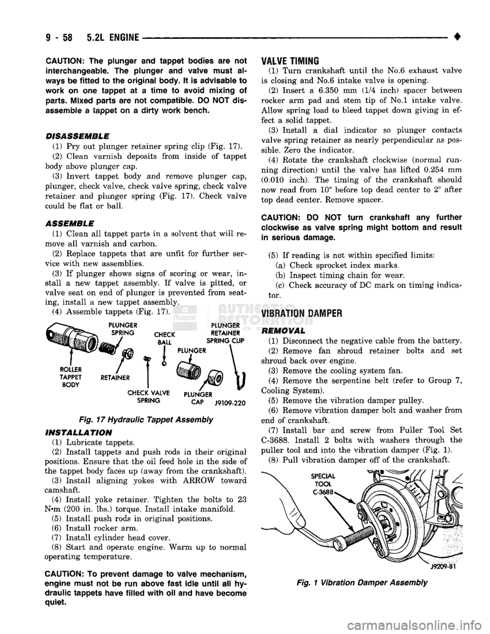
(1) Pry out plunger retainer spring clip (Fig. 17).
(2) Clean varnish deposits from inside of tappet
body above plunger cap.
(3) Invert tappet body and remove plunger cap,
plunger, check valve, check valve spring, check valve
retainer and plunger spring (Fig. 17). Check valve could be flat or ball.
ASSEMBLE
(1) Clean all tappet parts in a solvent that will re
move all varnish and carbon.
(2) Replace tappets that are unfit for further ser
vice with new assemblies.
(3) If plunger shows signs of scoring or wear, in
stall a new tappet assembly. If valve is pitted, or
valve seat on end of plunger is prevented from seat
ing, install a new tappet assembly. (4) Assemble tappets (Fig. 17).
PLUNGER
CHECK
BALL
PLUNGER
RETAINER
SPRING CLIP
ROLLER
TAPPET BODY RETAINER I PLUNGER
CHECK VALVE
SPRING PLUNGER
CAP
J9109-220
Fig.
17 Hydraulic
Tappet
Assembly
INSTALLATION
(1) Lubricate tappets.
(2) Install tappets and push rods in their original
positions. Ensure that the oil feed hole in the side of
the tappet body faces up (away from the crankshaft). (3) Install aligning yokes with ARROW toward
camshaft. (4) Install yoke retainer. Tighten the bolts to 23
N»m (200 in. lbs.) torque. Install intake manifold. (5) Install push rods in original positions.
(6) Install rocker arm.
(7) Install cylinder head cover.
(8) Start and operate engine. Warm up to normal
operating temperature.
CAUTION: To
prevent
damage to valve mechanism,
engine must not be run above
fast
idle
until
all hy
draulic
tappets
have
filled
with
oil and have become
quiet.
VALVE
TIMING
(1) Turn crankshaft until the No.6 exhaust valve
is closing and No.6 intake valve is opening. (2) Insert a 6.350 mm (1/4 inch) spacer between
rocker arm pad and stem tip of No.l intake valve. Allow spring load to bleed tappet down giving in ef
fect a solid tappet. (3) Install a dial indicator so plunger contacts
valve spring retainer as nearly perpendicular as pos
sible.
Zero the indicator. (4) Rotate the crankshaft clockwise (normal run
ning direction) until the valve has lifted 0.254 mm (0.010 inch). The timing of the crankshaft should
now read from 10° before top dead center to 2° after
top dead center. Remove spacer.
CAUTION:
DO NOT
turn
crankshaft any
further
clockwise as valve spring
might
bottom
and
result
in serious
damage.
(5) If reading is not within specified limits: (a) Check sprocket index marks.
(b) Inspect timing chain for wear.
(c) Check accuracy of DC mark on timing indica
tor.
VIBRATION DAMPER
REMOVAL (1) Disconnect the negative cable from the battery.
(2) Remove fan shroud retainer bolts and set
shroud back over engine.
(3) Remove the cooling system fan.
(4) Remove the serpentine belt (refer to Group 7,
Cooling System).
(5) Remove the vibration damper pulley. (6) Remove vibration damper bolt and washer from
end of crankshaft. (7) Install bar and screw from Puller Tool Set
C-3688. Install 2 bolts with washers through the
puller tool and into the vibration damper (Fig. 1).
(8) Pull vibration damper off of the crankshaft.
J9209-81
Fig.
1
Vibration
Damper
Assembly
Page 668 of 1502
•
5.2L
ENGINE
I - 63
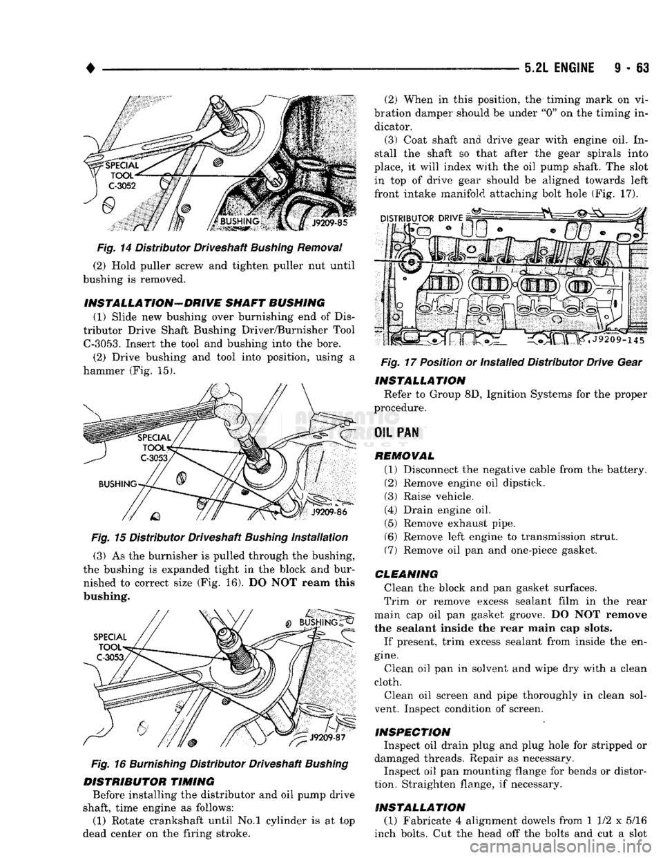
Fig.
14 Distributor Driveshaft
Bushing
Removal
(2) Hold puller screw and tighten puller nut until
bushing is removed.
INSTALLA TION-DRIVE
SHAFT BUSHING
(1) Slide new bushing over burnishing end of Dis
tributor Drive Shaft Bushing Driver/Burnisher Tool
C-3053.
Insert the tool and bushing into the bore. (2) Drive bushing and tool into position, using a
hammer (Fig. 15).
Fig. 15 Distributor Driveshaft Bushing Installation (3) As the burnisher is pulled through the bushing,
the bushing is expanded tight in the block and bur nished to correct size (Fig. 16). DO NOT ream this
bushing.
Fig.
16
Burnishing
Distributor Driveshaft
Bushing
DISTRIBUTOR TIMING Before installing the distributor and oil pump drive
shaft, time engine as follows:
(1) Rotate crankshaft until No.l cylinder is at top
dead center on the firing stroke. (2) When in this position, the timing mark on vi
bration damper should be under "0" on the timing in dicator.
(3) Coat shaft and drive gear with engine oil. In
stall the shaft so that after the gear spirals into
place, it will index with the oil pump shaft. The slot in top of drive gear should be aligned towards left
front intake manifold attaching bolt hole (Fig. 17).
Fig.
17 Position or Installed Distributor Drive Gear
INSTALLATION Refer to Group 8D, Ignition Systems for the proper
procedure.
OIL
PAN REMOVAL (1) Disconnect the negative cable from the battery.
(2) Remove engine oil dipstick. (3) Raise vehicle.
(4) Drain engine oil. (5) Remove exhaust pipe.
(6) Remove left engine to transmission strut.
(7) Remove oil pan and one-piece gasket.
CLEANING Clean the block and pan gasket surfaces.
Trim or remove excess sealant film in the rear
main cap oil pan gasket groove. DO NOT remove
the sealant inside the rear main cap slots.
If present, trim excess sealant from inside the en
gine.
Clean oil pan in solvent and wipe dry with a clean
cloth.
Clean oil screen and pipe thoroughly in clean sol
vent. Inspect condition of screen.
INSPECTION Inspect oil drain plug and plug hole for stripped or
damaged threads. Repair as necessary.
Inspect oil pan mounting flange for bends or distor
tion. Straighten flange, if necessary.
INSTALLATION (1) Fabricate 4 alignment dowels from 1 1/2 x 5/16
inch bolts. Cut the head off the bolts and cut a slot
Page 693 of 1502
9
- 88 5.9L
ENGINE
•
CAUTION:
The
plunger
and
tappet
bodies
are not
interchangeable,.
The
plunger
and
valve must
al
ways
be
fitted
to the
original
body,
It is
advisable
to
work
on one
tappet
at a time to
avoid mixing
of
parts. Mixed parts
are not
compatible.
DO
NOT dis
assemble
a
tappet
on a dirty
work bench.
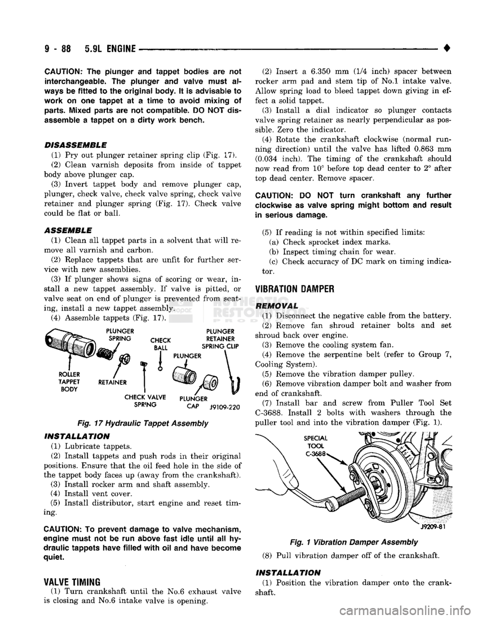
DISASSEMBLE (1) Pry out plunger retainer spring clip (Fig. 17).
(2) Clean varnish deposits from inside of tappet
body above plunger cap.
(3) Invert tappet body and remove plunger cap,
plunger, check valve, check valve spring, check valve
retainer and plunger spring (Fig, 17). Check valve
could be flat or ball.
ASSEMBLE
(1) Clean all tappet parts in a solvent that will re
move all varnish and carbon. (2) Replace tappets that are unfit for further ser
vice with new assemblies.
(3) If plunger shows signs of scoring or wear, in
stall a new tappet assembly. If valve is pitted, or
valve seat on end of plunger is prevented from seat ing, install a new tappet assembly.
(4) Assemble tappets (Fig. 17).
SPiING
CAP J9109-220
Fig.
17 Hydraulic
Tappet
Assembly INSTALLATION
(1) Lubricate tappets.
(2) Install tappets and push rods in their original
positions. Ensure that the oil feed hole In the side of
the tappet body faces up (away from the crankshaft). (3) Install rocker arm and shaft assembly.
(4) Install vent cover.
(5) Install distributor, start engine and reset tim
ing.
CAUTION:
To
prevent damage
to
valve mechanism,
engine must
not be run
above
fast
idle
until
all hy
draulic tappets have
filled
with oil and
have become
quiet.
¥AL¥E
TIMING
(1) Turn crankshaft until the No.6 exhaust valve
is closing and No.6 intake valve Is opening. (2) Insert a 6.350 mm (1/4 inch) spacer between
rocker arm pad and stem tip of No.l intake valve.
Allow spring load to bleed tappet down giving in ef
fect a solid tappet. (3) Install a dial indicator so plunger contacts
valve spring retainer as nearly perpendicular as pos
sible.
Zero the Indicator.
(4) Rotate the crankshaft clockwise (normal run
ning direction) until the valve has lifted 0.863 mm (0.034 inch). The timing of the crankshaft should
now read from 10° before top dead center to 2° after
top dead center. Remove spacer.
CAUTION:
DO NOT
turn crankshaft
any
further
clockwise
as
valve spring might bottom
and
result
in serious damage.
(5) If reading is not within specified limits: (a) Check sprocket index marks.
(b) Inspect timing chain for wear.
(c) Check accuracy of DC mark on timing indica
tor. -
¥IBRATI0N
PAMPER
REMOVAL (1) Disconnect the negative cable from the battery.
(2) Remove fan shroud retainer bolts and set
shroud back over engine. (3) Remove the cooling system fan.
(4) Remove the serpentine belt (refer to Group 7,
Cooling System). (5) Remove the vibration damper pulley. (6) Remove vibration damper bolt and washer from
end of crankshaft. (7) Install bar and screw from Puller Tool Set
C-3688. Install 2 bolts with washers through the
puller tool and into the vibration damper (Fig. 1).
J9209-81
Fig.
1
Vibration
Damper
Assembly
(8) Pull vibration damper off of the crankshaft.
INSTALLATION (1) Position the vibration damper onto the crank
shaft.
Page 698 of 1502
•
5.9L
ENGINE
9 - 93
Fig.
14
Removing
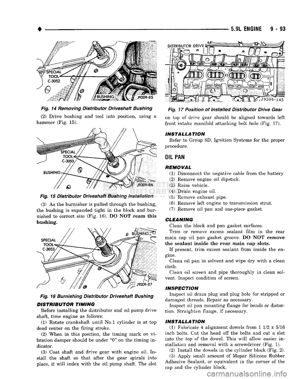
Distributor Driveshaft
Bushing
(2) Drive bushing and tool into position, using a
hammer (Fig. 15).
Fig.
15 Distributor Driveshaft
Bushing
Installation
(3) As the burnisher is pulled through the bushing,
the bushing is expanded tight in the block and bur nished to correct size (Fig. 16). DO NOT ream this
bushing.
Fig.
16
Burnishing
Distributor Driveshaft
Bushing
DISTRIBUTOR
TIMING
Before installing the distributor and oil pump drive
shaft, time engine as follows: (1) Rotate crankshaft until No.l cylinder is at top
dead center on the firing stroke. (2) When in this position, the timing mark on vi
bration damper should be under "0" on the timing in dicator.
(3) Coat shaft and drive gear with engine oil. In
stall the shaft so that after the gear spirals into
place, it will index with the oil pump shaft. The slot
Fig.
17 Position of Installed Distributor Drive Gear
on top of drive gear should be aligned towards left
front intake manifold attaching bolt hole (Fig. 17).
INSTALLATION
Refer to Group 8D, Ignition Systems for the proper
procedure.
OIL
PAN
REMOVAL
(1) Disconnect the negative cable from the battery.
(2) Remove engine oil dipstick.
(3) Raise vehicle.
(4) Drain engine oil. (5) Remove exhaust pipe.
(6) Remove left engine to transmission strut.
(7) Remove oil pan and one-piece gasket.
CLEANING
Clean the block and pan gasket surfaces.
Trim or remove excess sealant film in the rear
main cap oil pan gasket groove. DO NOT remove
the sealant inside the rear main cap slots.
If present, trim excess sealant from inside the en
gine.
Clean oil pan in solvent and wipe dry with a clean
cloth. Clean oil screen and pipe thoroughly in clean sol
vent. Inspect condition of screen.
INSPECTION
Inspect oil drain plug and plug hole for stripped or
damaged threads. Repair as necessary.
Inspect oil pan mounting flange for bends or distor
tion. Straighten flange, if necessary.
INSTALLATION
(1) Fabricate 4 alignment dowels from 1 1/2 x 5/16
inch bolts. Cut the head off the bolts and cut a slot into the top of the dowel. This will allow easier installation and removal with a screwdriver (Fig. 1).
(2) Install the dowels in the cylinder block (Fig. 2). (3) Apply small amount of Mopar Silicone Rubber
Adhesive Sealant, or equivalent in the corner of the cap and the cylinder block.