1993 DODGE TRUCK dimensions
[x] Cancel search: dimensionsPage 6 of 1502
INTRODUCTION
INTRODUCTION
DESIGNATIONS,
LABELS/PLATES/DECALS,
CODES
AND DIMENSIONS/WEIGHTS .
CONTENTS
page
MEASUREMENT
AND TORQUE
... 1 SPECIFICATIONS
page
. 11
DESIGNATIONS, LABELS/PLATES/DECALS, CODES
AND
DIMENSIONS/WEIGHTS
INDEX
page
Engine
and
Transmission/Transfer
Case
Identification
2
Engine/Transmission/GVWR
4
Equipment
Identification
Plate
3
International
Vehicle Control
and
Display
Symbols
10
Major Component
Identification 3
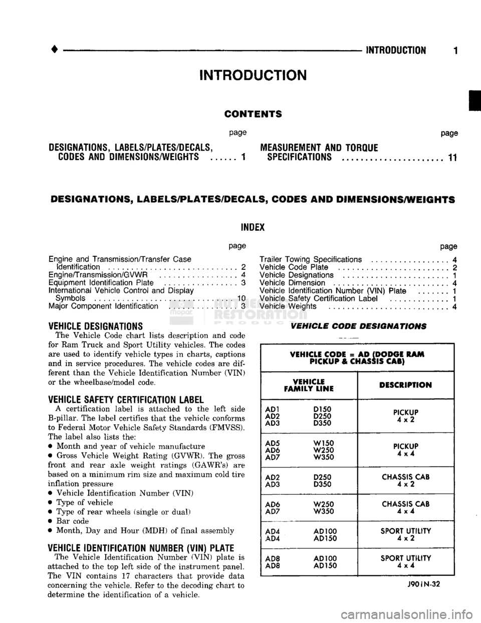
VEHICLE DESIGNATIONS The Vehicle Code chart lists description and code
for Ram Truck and Sport Utility vehicles. The codes are used to identify vehicle types in charts, captions
and in service procedures. The vehicle codes are
dif
ferent than the Vehicle Identification Number (VIN) or the wheelbase/model code.
VEHICLE SAFETY CERTIFICATION
LABEL
A certification label is attached to the left side
B-pillar. The label certifies that the vehicle conforms
to Federal Motor Vehicle Safety Standards (FMVSS).
The label also lists the: • Month and year of vehicle manufacture
• Gross Vehicle Weight Rating (GVWR). The gross
front and rear axle weight ratings (GAWR's) are
based on a minimum rim size and maximum cold tire inflation pressure Vehicle Identification Number (VIN)
Type of vehicle
Type of rear wheels (single or dual) Bar code
Month, Day and Hour (MDH) of final assembly
VEHICLE IDENTIFICATION NUMBER (VIN) PLATE The Vehicle Identification Number (VIN) plate is
attached to the top left side of the instrument panel.
The VIN contains 17 characters that provide data
concerning the vehicle. Refer to the decoding chart to
determine the identification of a vehicle.
page
Trailer
Towing Specifications
4
Vehicle Code Plate
2
Vehicle Designations
1
Vehicle Dimension
4
Vehicle
Identification
Number (VIN) Plate
1
Vehicle Safety
Certification
Label
............. 1
Vehicle Weights
4
VEHICLE CODE
DESIGNATIONS
VEHICLE CODE
= AD
(DODGE
RAM
PICKUP
&
CHASSIS
CAB)
VEHICLE
FAMILY LINE DESCRIPTION
AD1
D150
AD2
D250
AD3
D350
PICKUP
4x2
AD5
W150
AD6
W250
AD7
W350
PICKUP
4x4
AD2
D250
AD3
D350
CHASSIS
CAB
4x2
AD6
W250
AD7
W350
CHASSIS
CAB
4x4
AD4
AD100
AD4
AD150
SPORT
UTILITY
4x2
AD8
AD100
AD8 AD
150
SPORT
UTILITY
4x4
J90IN-32
Page 9 of 1502
4 INTRODUCTION
• VEHICLE DIMENSIONS
VEHICLE
FAMILY
WHEELBASE
AVAILABLE
CAB
TO
AXLE BODY
TYPE
SfANDAID
SODIES
AVAILABLE
VEHICLE
FAMILY
WHEELBASE
AVAILABLE
CAB
TO
AXLE BODY
TYPE
NOMINAL
LENGTH
(LOAD
SPACE
D
MENSIONS
(2)
VEHICLE
FAMILY
WHEELBASE
AVAILABLE
CAB
TO
AXLE BODY
TYPE
NOMINAL
LENGTH LENGTH MAX.
WIDTH
HEIGHT
VOLUME
AD-1
AD-5
2921
mm
(115
in) —
Sweptline
1981
mm
(6.5
ft)
1981
mm
(78
in)
1778 mm
(70
in)
485 mm
19.1
in) 1.71 m3
(60.35
ft3)
AD-1
AD-2
AD-3
AD-5
AD-6
AD-7
3327
mm
(131
in) —
Sweptline
2438 mm
(8
ft)
2489 mm
(98
in)
1778 mm
(70
in)
485 mm
(19.1
in)
2.15
m3
(75.8
ft3)
AD-2
AD-3
AD-7
3327
mm
(131
in)
1422 mm
(56
in)
Chassis
Cab
2438 mm
(8
ft)
—
— — —
AD-3
AD-7
3249 mm
(135
in)
1524 mm
(60
in)
Chassis
Cab
2896 mm
(9.5
ft) —
— — —
AD-3
4039 mm
(159
in)
2134 mm
(84
in)
Chassis
Cab
3810 mm
(12.5
ft)
—
— —
AD-4
2692
mm
(106
in)
Sport
Utility
4x2
—
1778 mm 1588 mm
(62.5
in)
1062 mm
(41.8
in)
2.99
m3
(105.8
ft3)
AD-8
2692
mm
(106
in)
Sport
Utility
4x4
—
1778 mm 1588 mm
(62.5
in)
1062 mm
(41.8
in)
2.99
m3
(105.8
ft3)
AD-1
3378 mm
(133
in) —
Sweptline
1981
mm
(6.5
ft)
1984 mm
(78.1
in)
1778 mm
(70
in)
485 mm
(19.1
in) 1.71 m3
(60.4
ft3)
AD-1
AD-2
AD-5
AD-6
3785 mm
(149
in) —
Sweptline
Club
Cab 2438 mm
(8
ft)
2489 mm
(98
in)
1778 mm
(70
in)
485 mm
(19.1
in)
2.15
M3
(75.8
ft3)
®
Driver seat
to
tailgate.
(2)
Based
on
S.A.E.
procedure
Jl
100. J901N-34
VEHICLE
WEIGHTS
The Vehicle Weights chart provides:
• The Gross Vehicle Weight Rating (GVWR),
• The payload
• The curb weight
for
each vehicle type/wheelbase
TRAILER
TOWING
SPECIFICATIONS
The Trailer Towing Specifications chart provides:
• The maximum trailer tongue weight
• The maximum trailer weight
• The maximum combined weight of the trailer/load/
towing vehicle with
a
specific engine/transmission/ axle combination.
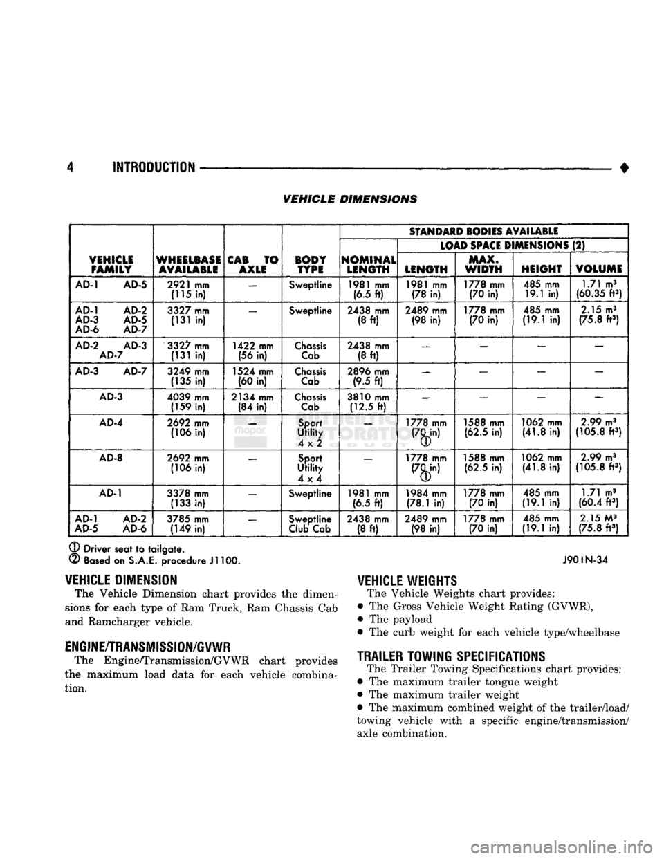
VEHICLE
DIMENSION
The Vehicle Dimension chart provides
the
dimen
sions
for
each type
of
Ram Truck, Ram Chassis Cab
and Ramcharger vehicle.
ENGINE/TRANSMISSION/GVWR
The Engine/Transmission/GVWR chart provides
the maximum load data
for
each vehicle combina tion.
Page 736 of 1502
•
5.9L (DIESEL) ENGINE
9 - 131
1st REFACE
0.15 mm
(0.0058
inch)
2nd REFACE
0.35 mm
(0.0138
inch)
®
Total
0.50
mm
(0.0197
inch)
®
Standard
323.00
mm ±0.10 mn i
(12.7165
inch
±0.0039
inch)
1st
RE
FACE
322.85 mm ±0.10 mm
(12.7106
inch
±0.0039
inch)
2nd
REFACE
322.50
mm ±0.10 mn i
(12.6968
inch
±0.0039
inch)
J9109-118
Fig.
7 Refacing
Dimensions
of the Cylinder
Block
1st REFACE
X
2nd REFACE
XX
J9109-116
Fig.
8
Stamp
Block
after
Reface
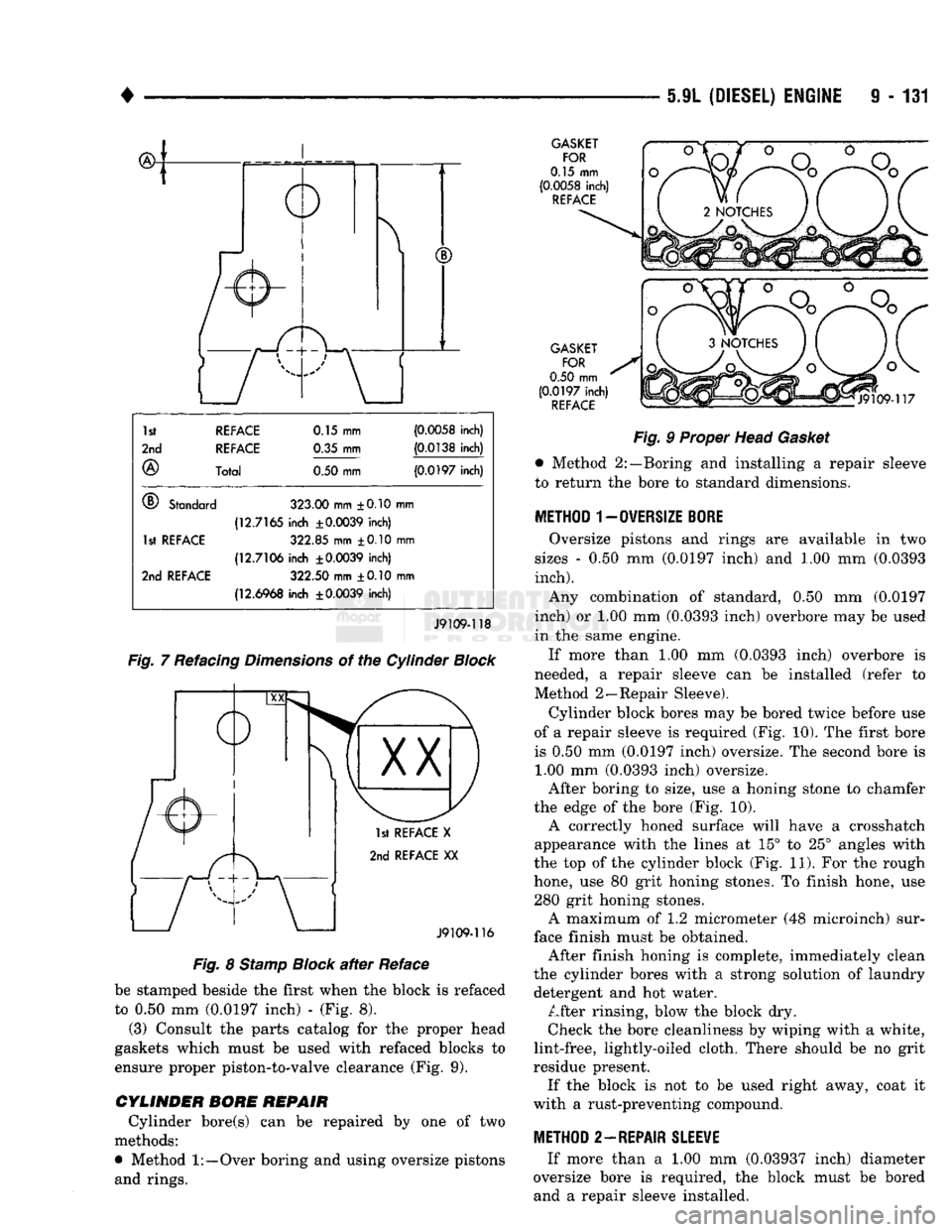
be stamped beside the first when the block is refaced
to 0.50 mm (0.0197 inch) - (Fig. 8). (3) Consult the parts catalog for the proper head
gaskets which must be used with refaced blocks to
ensure proper piston-to-valve clearance (Fig. 9).
CYLINDER BORE REPAIR Cylinder bore(s) can be repaired by one of two
methods:
•
Method
1:—Over
boring and using oversize pistons and rings.
GASKET
FOR
0.15 mm
(0.0058
inch)
REFACE
GASKET FOR
0.50
mm
(0.0197
inch)
REFACE
Fig.
9 Proper Head
Gasket
•
Method 2:—Boring and installing a repair sleeve
to leturn the bore to standard dimensions.
METHOD 1-0WERS1ZE
BORE
Oversize pistons and rings are available in two
sizes - 0.50 mm (0.0197 inch) and 1.00 mm (0.0393
inch).
Any combination of standard, 0.50 mm (0.0197
inch) or 1.00 mm (0.0393 inch) overbore may be used
in the same engine.
If more than 1.00 mm (0.0393 inch) overbore is
needed, a repair sleeve can be installed (refer to
Method 2—Repair Sleeve).
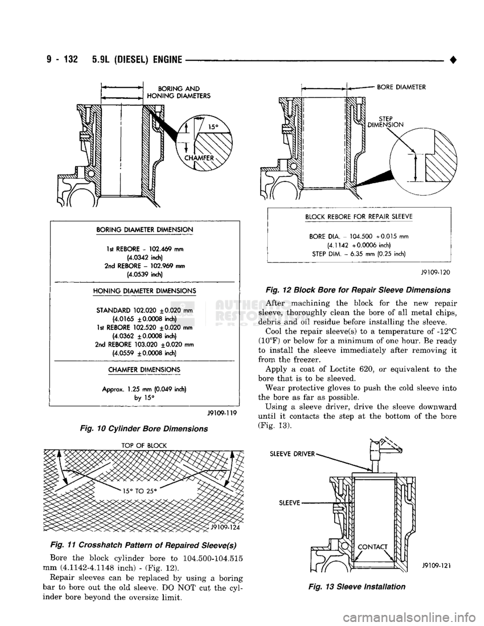
Cylinder block bores may be bored twice before use
of a repair sleeve is required (Fig. 10). The first bore
is 0.50 mm (0.0197 inch) oversize. The second bore is 1.00 mm (0.0393 inch) oversize.
After boring to size, use a honing stone to chamfer
the edge of the bore (Fig. 10). A correctly honed surface will have a Crosshatch
appearance with the lines at 15° to 25° angles with
the top of the cylinder block (Fig. 11). For the rough
hone, use 80 grit honing stones. To finish hone, use 280 grit honing stones. A maximum of 1.2 micrometer (48 microinch) sur
face finish must be obtained. After finish honing is complete, immediately clean
the cylinder bores with a strong solution of laundry detergent and hot water. After rinsing, blow the block dry. Check the bore cleanliness by wiping with a white,
lint-free, lightly-oiled cloth. There should be no grit
residue present. If the block is not to be used right away, coat it
with a rust-preventing compound.
METHOD 2—REPAIR
SLEEWE
If more than a 1.00 mm (0.03937 inch) diameter
oversize bore is required, the block must be bored and a repair sleeve installed.
Page 737 of 1502
9
- 132 5.9L
(DIESEL) ENGINE
BORING
AND
HONING
DIAMETERS
BORING DIAMETER DIMENSION 1st REBORE
-
102.469
mm
(4.0342
inch)
2nd
REBORE
-
102.969
mm
(4.0539
inch)
HONING
DIAMETER DIMENSIONS
STANDARD
102.020
±0.020
mm
(4.0165
±
0.0008
inch)
1st REBORE
102.520
±
0.020
mm
(4.0362
±
0.0008
inch)
2nd
REBORE
103.020
±0.020
mm
(4.0559
±
0.0008
inch)
CHAMFER DIMENSIONS
Approx.
1.25 mm
(0.049
inch)
by
15°
J9109-119
Fig.
10 Cylinder
Bore
Dimensions
TOP
OF
BLOCK
Fig.
11
Crosshatch
Pattern
of Repaired
Sleeve(s)
Bore the block cylinder bore to 104.500-104.515
mm (4.1142-4.1148 inch) - (Fig. 12).
Repair sleeves can be replaced by using a boring
bar to bore out the old sleeve. DO NOT cut the cyl
inder bore beyond the oversize limit.
BORE DIAMETER
BLOCK REBORE
FOR
REPAIR SLEEVE BORE
DIA. -
104.500
+0.015
mm
(4.1142
+0.0006
inch)
STEP
DIM. - 6.35 mm (0.25 inch)
J9109-120
Fig.
12
Block
Bore
for Repair
Sleeve
Dimensions
After machining the block for the new repair
sleeve, thoroughly clean the bore of all metal chips,
debris and oil residue before installing the sleeve.
Cool the repair sleeve(s) to a temperature of -12°C
(10°F) or below for a minimum of one hour. Be ready
to install the sleeve immediately after removing it
from the freezer.
Apply a coat of Loctite 620, or equivalent to the
bore that is to be sleeved. Wear protective gloves to push the cold sleeve into
the bore as far as possible.
Using a sleeve driver, drive the sleeve downward
until it contacts the step at the bottom of the bore (Fig. 13).
J9109-121
Fig.
13
Sleeve
Installation
Page 738 of 1502
•
5
9L
(DIESEL) ENGINE
9 - 133
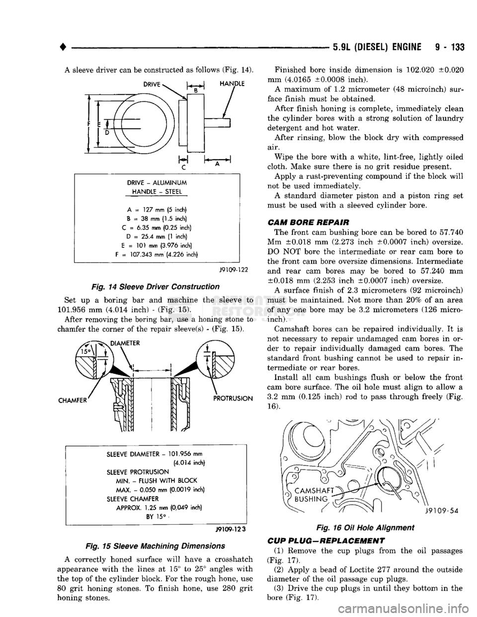
A sleeve driver can be constructed as follows (Fig. 14).
DRIVE
-
ALUMINUM
HANDLE
-
STEEL A
= 127 mm (5 inch)
B
= 38 mm (1.5 inch)
C
= 6.35 mm (0.25 inch)
D
= 25.4 mm (1 inch)
E
= 101 mm
(3.976
inch)
F
=
107.343
mm
(4.226
inch)
J9109-122
Fig.
14
Sleeve
Driver Construction
Set up a boring bar and machine the sleeve to
101.956 mm (4.014 inch) - (Fig. 15). After removing the boring bar, use a honing stone to
chamfer the corner of the repair sleeve(s) - (Fig. 15).
SLEEVE DIAMETER
-
101.956
mm
(4.014
inch)
SLEEVE PROTRUSION MIN.
-
FLUSH
WITH
BLOCK MAX.
-
0.050
mm
(0.0019
inch)
SLEEVE CHAMFER APPROX.
1.25 mm
(0,049
inch)
BY
15° •
J9109-123
Fig.
15
Sleeve
Machining
Dimensions
A correctly honed surface will have a Crosshatch
appearance with the lines at 15° to 25° angles with
the top of the cylinder block. For the rough hone, use 80 grit honing stones. To finish hone, use 280 grit
honing stones. Finished bore inside dimension is 102.020 ±0.020
mm (4.0165 ±0.0008 inch). A maximum of 1.2 micrometer (48 microinch) sur
face finish must be obtained.
After finish honing is complete, immediately clean
the cylinder bores with a strong solution of laundry detergent and hot water.
After rinsing, blow the block dry with compressed
air.
Wipe the bore with a white, lint-free, lightly oiled
cloth. Make sure there is no grit residue present. Apply a rust-preventing compound if the block will
not be used immediately.
A standard diameter piston and a piston ring set
must be used with a sleeved cylinder bore.
CAM
BORE REPAIR
The front cam bushing bore can be bored to 57.740
Mm ±0.018 mm (2.273 inch ±0.0007 inch) oversize.
DO NOT bore the intermediate or rear cam bore to
the front cam bore oversize dimensions. Intermediate and rear cam bores may be bored to 57.240 mm ±0.018 mm (2.253 inch ±0.0007 inch) oversize.
A surface finish of 2.3 micrometers (92 microinch)
must be maintained. Not more than 20% of an area
of any one bore may be 3.2 micrometers (126 micro-
inch).
Camshaft bores can be repaired individually. It is
not necessary to repair undamaged cam bores in or
der to repair individually damaged cam bores. The standard front bushing cannot be used to repair in
termediate or rear bores.
Install all cam bushings flush or below the front
cam bore surface. The oil hole must align to allow a 3.2 mm (0.125 inch) rod to pass through freely (Fig.
16). Fig.
16 Oil Hole
Alignment
CUP PLUG-REPLACEMENT
(1) Remove the cup plugs from the oil passages
(Fig. 17).
(2) Apply a bead of Loctite 277 around the outside
diameter of the oil passage cup plugs. (3) Drive the cup plugs in until they bottom in the
bore (Fig. 17).
Page 744 of 1502
•
5.9L
(DIESEL) ENGINE 9 - 139
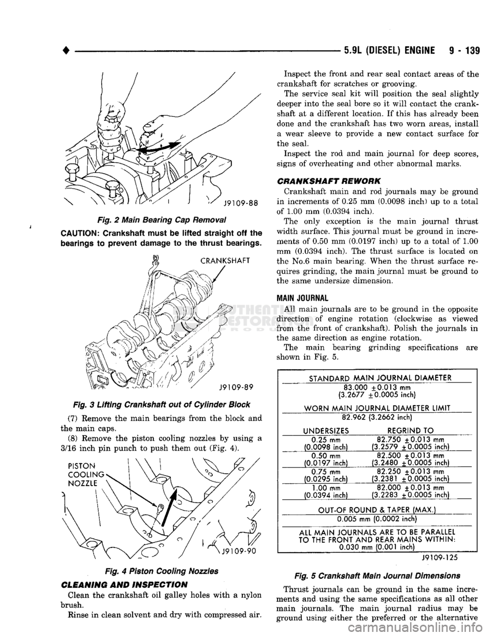
Fig.
2 Main Beating Cap
Removal
CAUTION:
Crankshaft must be
lifted
straight
off the
bearings
to
prevent
damage
to the
thrust
bearings.
Fig.
3 Lifting Crankshaft out of Cylinder
Block
(7)
Remove the main bearings from the block and
the main caps. (8) Remove the piston cooling nozzles by using a
3/16 inch pin punch to push them out (Fig. 4).
Fig.
4
Piston
Cooling
Nozzles
CLEANING
AND
INSPECTION
Clean the crankshaft oil galley holes with a nylon
brush. Rinse in clean solvent and dry with compressed air. Inspect the front and rear seal contact areas of the
crankshaft for scratches or grooving. The service seal kit will position the seal slightly
deeper into the seal bore so it will contact the crank
shaft at a different location. If this has already been
done and the crankshaft has two worn areas, install
a wear sleeve to provide a new contact surface for
the seal.
Inspect the rod and main journal for deep scores,
signs of overheating and other abnormal marks.
CRANKSHAFT
REWORK
Crankshaft main and rod journals may be ground
in increments of 0.25 mm (0.0098 inch) up to a total
of 1.00 mm (0.0394 inch). The only exception is the main journal thrust
width surface. This journal must be ground in incre ments of 0.50 mm (0.0197 inch) up to a total of 1.00
mm (0.0394 inch). The thrust surface is located on
the No.6 main bearing. When the thrust surface re quires grinding, the main journal must be ground to
the same undersize dimension.
MAIN
JOURNAL
All main journals are to be ground in the opposite
direction of engine rotation (clockwise as viewed
from the front of crankshaft). Polish the journals in
the same direction as engine rotation.
The main bearing grinding specifications are
shown in Fig. 5.
STANDARD
MAIN
JOURNAL
DIAMETER
83.000 +0.013 mm
(3.2677 ±0.0005 inch)
WORN
MAIN
JOURNAL
DIAMETER
LIMIT
82.962 (3.2662
inch)
UNDERSIZES
REGRIND
TO
0.25 mm
(0.0098
inch)
82.750 ±0.013 mm
(3.2579 ±0.0005
inch)
0.50 mm
(0.0197
inch)
82.500 +0.013 mm
(3.2480 +0.0005
inch)
0.75 mm
(0.0295
inch)
82.250 +0.013 mm
(3.2381 ±0.0005
inch)
1.00 mm
(0.0394 inch) 82.000 +0.013 mm
(3.2283 ±0.0005 inch)
OUT-OF
ROUND
&
TAPER
(MAX.)
0.005 mm (0.0002 inch)
ALL
MAIN
JOURNALS
ARE
TO
BE
PARALLEL
TO
THE
FRONT
AND
REAR
MAINS
WITHIN:
0.030
mm
(0.001 inch)
J9109-125
Fig.
5 Crankshaft Main
Journal
Dimensions
Thrust journals can be ground in the same incre
ments and using the same specifications as all other main journals. The main journal radius may be ground using either the preferred or the alternative
Page 745 of 1502
9
- 140 5.9L
(DIESEL)
ENGINE
• procedure providing
the
thrust surface width
is not
being ground.
The
preferred procedure must
be
used
when
the
main bearing thrust width surface
is
ground. When
the
thrust surface width requires
grinding,
the
main journal must
be
ground
to the
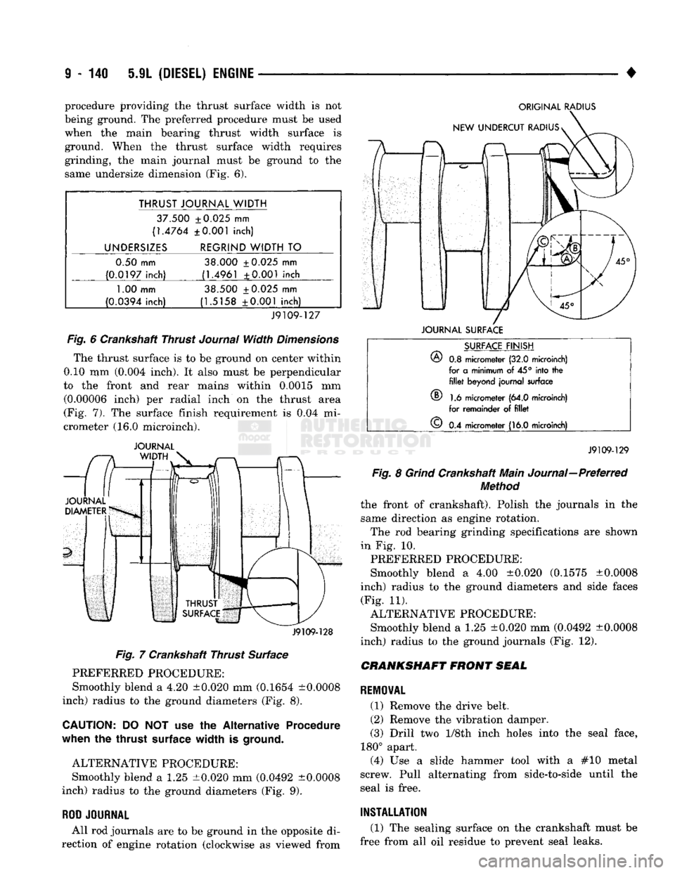
same undersize dimension
(Fig. 6).
THRUST JOURNAL WIDTH
37.500 ±0.025
mm
(1.4764 ±0.001 inch)
UNDERSIZES REGRIND WIDTH
TO
0.50 mm 38.000 ±0.025
mm
(0.0197 inch) (1.4961 ±0.001 inch
1.00
mm 38.500 ±0.025
mm
(0.0394 inch) (1.5158 ±0.001 inch)
J9109-127
Fig.
6
Crankshaft Thrust
Journal
Width
Dimensions
The thrust surface
is to be
ground
on
center within
0.10
mm
(0.004 inch).
It
also must
be
perpendicular
to
the
front
and
rear mains within 0.0015
mm
(0.00006 inch)
per
radial inch
on the
thrust area
(Fig.
7). The
surface finish requirement
is 0.04 mi
crometer
(16.0
microinch).
JOURNAL
J9109-128
Fig.
7
Crankshaft Thrust Surface PREFERRED PROCEDURE:
Smoothly blend
a 4.20
±0.020
mm
(0.1654 ±0.0008
inch) radius
to the
ground diameters
(Fig. 8).
CAUTION:
DO NOT use the
Alternative Procedure
when
the
thrust
surface
width
is
ground.
ALTERNATIVE PROCEDURE: Smoothly blend
a 1.25
±0.020
mm
(0.0492 ±0.0008
inch) radius
to the
ground diameters
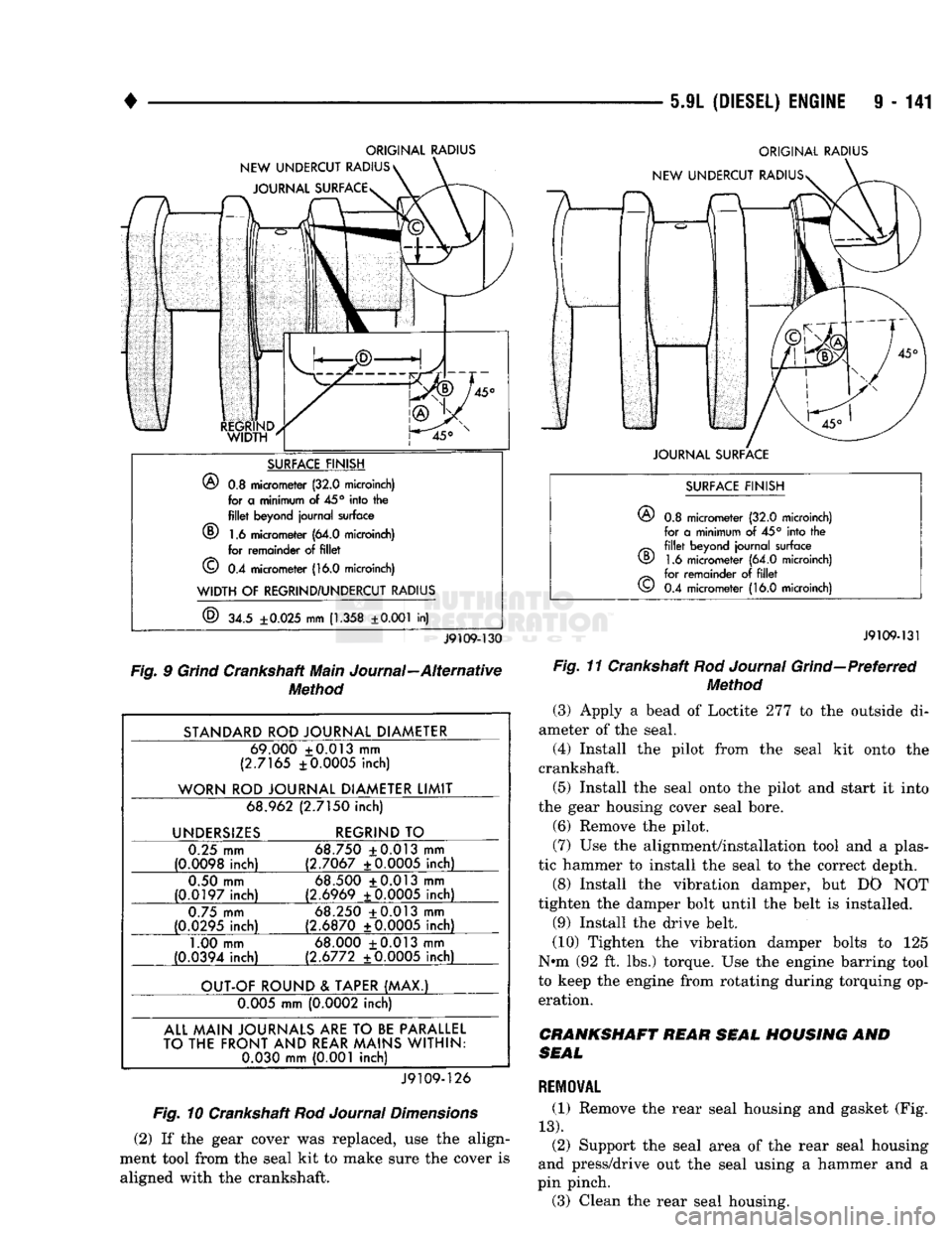
(Fig. 9).
ROD
JOURNAL
All
rod
journals
are to be
ground
in the
opposite
di
rection
of
engine rotation (clockwise
as
viewed from
ORIGINAL
RADIUS
JOURNAL
SURFACE
®
SURFACE
FINISH
®
0.8
micrometer
(32.0
microinch)
for
a
minimum
of 45°
into
the fillet
beyond journal surface
1.6
micrometer
(64.0
microinch)
for remainder
of fillet
©
0.4
micrometer
(16.0
microinch)
J9109-129
Fig.
8
Grind
Crankshaft Main Journal—Preferred
Method
the front
of
crankshaft). Polish
the
journals
in the
same direction
as
engine rotation. The
rod
bearing grinding specifications
are
shown
in
Fig. 10.
PREFERRED PROCEDURE:
Smoothly blend
a 4.00
±0.020 (0.1575 ±0.0008
inch) radius
to the
ground diameters
and
side faces (Fig.
11).
ALTERNATIVE PROCEDURE: Smoothly blend
a 1.25
±0.020
mm
(0.0492 ±0.0008
inch) radius
to the
ground journals
(Fig. 12).
CRANKSHAFT
FRONT
SEAL
REMOVAL
(1) Remove
the
drive belt.
(2) Remove
the
vibration damper.
(3) Drill
two 1/Sth
inch holes into
the
seal face,
180° apart. (4)
Use a
slide hammer tool with
a #10
metal
screw. Pull alternating from side-to-side until
the
seal
is
free.
INSTALLATION
(1)
The
sealing surface
on the
crankshaft must
be
free from
all oil
residue
to
prevent seal leaks.
Page 746 of 1502
5-9L
(DIESEL) ENGINE
9 - 141
ORIGINAL RADIUS
NEW UNDERCUT RADIUS JOURNAL SURFACE ORIGINAL RADIUS
NEW UNDERCUT RADIUSs
SURFACE FINISH
®
0.8 micrometer (32.0 microinch) for a minimum of
45°
into the
fillet
beyond journal surface
(D 1.6 micrometer (64.0 microinch) for remainder of
fillet
©
0.4 micrometer (16.0 microinch)
WIDTH
OF
REGRIND/UNDERCUT RADIUS
®
34.5
±0.025
mm
(1.358
±0.001
in)
JOURNAL SURFACE
J9109-130
Fig. 9 Grind Crankshaft Main Journal—Alternative Method
STANDARD ROD JOURNAL DIAMETER 69.000 +0.013 mm
(2.7165 ±0.0005 inch)
WORN ROD JOURNAL DIAMETER LIMIT 68.962 (2.7150 inch)
UNDERSIZES REGRIND TO
0.25 mm
(0.0098 inch) 68.750 +0.013 mm
(2.7067 ±0.0005 inch)
0.50 mm
(0.0197 inch) 68.500 +0.013 mm
(2.6969 ±0.0005 inch)
0.75 mm
(0.0295 inch) 68.250 +0.013 mm
(2.6870 ±0.0005 inch)
1.00 mm
(0.0394 inch) 68.000 +0.013 mm
(2.6772 ±0.0005 inch)
OUT-OF ROUND & TAPER (MAX.) 0.005 mm (0.0002 inch)
ALL MAIN JOURNALS
ARE
TO
BE
PARALLEL
TO THE FRONT AND REAR MAINS WITHIN: 0.030 mm (0.001 inch)
J9109-126
Fig. 10 Crankshaft Rod Journal Dimensions
(2) If the gear cover was replaced, use the align
ment tool from the seal kit to make sure the cover is aligned with the crankshaft.
SURFACE FINISH
©
0.8 micrometer (32.0 microinch)
for a minimum of 45° into the
fillet
beyond journal surface 1.6 micrometer (64.0 microinch)
for remainder of
fillet
0.4 micrometer (16.0 microinch)
CD
©
J9109-131
Fig. 11 Crankshaft Rod Journal Grind—Preferred Method
(3) Apply a bead of Loctite 277 to the outside di
ameter of the seal.
(4) Install the pilot from the seal kit onto the
crankshaft.
(5) Install the seal onto the pilot and start it into
the gear housing cover seal bore. (6) Remove the pilot.
(7) Use the alignment/installation tool and a plas
tic hammer to install the seal to the correct depth.
(8) Install the vibration damper, but DO NOT
tighten the damper bolt until the belt is installed.
(9) Install the drive belt.
(10) Tighten the vibration damper bolts to 125
Nun (92 ft. lbs.) torque. Use the engine barring tool
to keep the engine from rotating during torquing op eration.
CRANKSHAFT REAR SEAL HOUSING AND
SEAL
REMOVAL
(1) Remove the rear seal housing and gasket (Fig.
13).
(2) Support the seal area of the rear seal housing
and press/drive out the seal using a hammer and a
pin pinch.
(3) Clean the rear seal housing.