1993 DODGE TRUCK buttons
[x] Cancel search: buttonsPage 416 of 1502

•
VEHICLE SPEED CONTROL SYSTEM
8H - 1
VEHICLE SPEED CONTROL SYSTEM
CONTENTS
SERVICE
PROCEDURES
page
. 11
TEST PROCEDURES
page
.. 7
GENERAL
INFORMATION
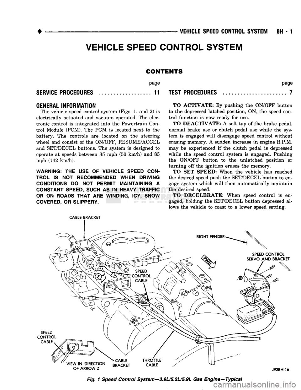
The vehicle speed control system (Figs. 1, and 2) is
electrically actuated and vacuum operated. The elec
tronic control is integrated into the Powertrain Con trol Module (PCM). The PCM is located next to the
battery. The controls are located on the steering
wheel and consist of the ON/OFF, RESUME/ACCEL and SET/DECEL buttons. The system is designed to
operate at speeds between 35 mph (50 km/h) and 85
mph (142 km/h).
WARNING: THE USE OF VEHICLE SPEED CON
TROL IS NOT RECOMMENDED WHEN DRIVING CONDITIONS DO NOT PERMIT MAINTAINING A CONSTANT SPEED, SUCH AS IN HEAVY TRAFFIC
OR ON ROADS THAT ARE WINDING, ICY, SNOW
COVERED, OR SLIPPERY.
CABLE
BRACKET
TO ACTIVATE: By pushing the ON/OFF button
to the depressed latched position, ON, the speed con
trol function is now ready for use.
TO DEACTIVATE: A soft tap of the brake pedal,
normal brake use or clutch pedal use while the sys
tem is engaged will disengage speed control without
erasing memory. A sudden increase in engine R.P.M.
may be experienced if the clutch pedal is depressed
while the speed control system is engaged. Pushing
the ON/OFF button to the unlatched position or
turning off the ignition erases the memory.
TO SET SPEED: When the vehicle has reached
the desired speed push the SET/DECEL button to en gage system which will then automatically maintain
the desired speed. TO DECELERATE: When speed control is en
gaged, holding the SET/DECEL button depressed al
lows the vehicle to coast to a lower speed setting.
SPEED
CONTROL
SERVO
AND BRACKET
SPEED
CONTROL
CABLE
»CABLE
VIEW
IN
DIRECTION RRAfKFT
OF ARROW
Z BRACKET J928H-16
Fig.
1
Speed
Control System—3.9L/5.2L/5.9L Gas Engine—Typical
Page 997 of 1502

19-36 STEERING
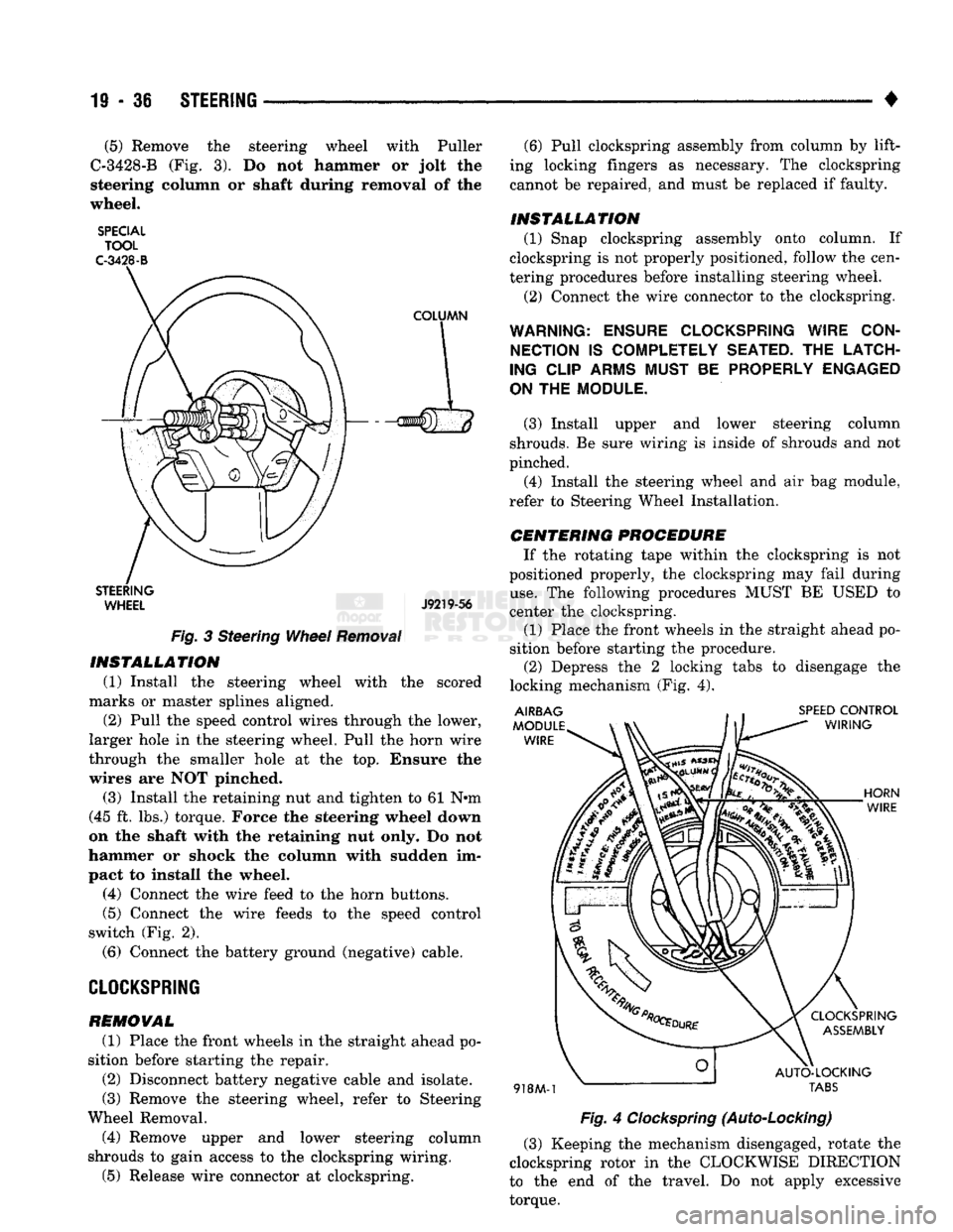
• (5) Remove the steering wheel with Puller
C-3428-B (Fig. 3). Do not hammer or jolt the
steering column or shaft during removal of the
wheel.
SPECIAL TOOL
C-3428-B
STEERING WHEEL J9219-56
Fig.
3 Steering
Wheel
Removal
INSTALLATION
(1) Install the steering wheel with the scored
marks or master splines aligned. (2) Pull the speed control wires through the lower,
larger hole in the steering wheel. Pull the horn wire
through the smaller hole at the top. Ensure the
wires are NOT pinched.
(3) Install the retaining nut and tighten to 61 N«m
(45 ft. lbs.) torque. Force the steering wheel down
on the shaft with the retaining nut only. Do not
hammer or shock the column with sudden im
pact to install the wheel.
(4) Connect the wire feed to the horn buttons.
(5) Connect the wire feeds to the speed control
switch (Fig. 2).
(6) Connect the battery ground (negative) cable.
CLOCKSPRING
REMOVAL
(1) Place the front wheels in the straight ahead po
sition before starting the repair.
(2) Disconnect battery negative cable and isolate.
(3) Remove the steering wheel, refer to Steering
Wheel Removal. (4) Remove upper and lower steering column
shrouds to gain access to the clockspring wiring.
(5) Release wire connector at clockspring. (6) Pull clockspring assembly from column by lift
ing locking fingers as necessary. The clockspring
cannot be repaired, and must be replaced if faulty.
INSTALLATION
(1) Snap clockspring assembly onto column. If
clockspring is not properly positioned, follow the cen
tering procedures before installing steering wheel.
(2) Connect the wire connector to the clockspring.
WARNING: ENSURE CLOCKSPRING WIRE CON NECTION
IS
COMPLETELY SEATED.
THE
LATCH
ING CLIP ARMS MUST
BE
PROPERLY ENGAGED
ON
THE
MODULE.
(3) Install upper and lower steering column
shrouds. Be sure wiring is inside of shrouds and not
pinched. (4) Install the steering wheel and air bag module,
refer to Steering Wheel Installation.
CENTERING
PROCEDURE
If the rotating tape within the clockspring is not
positioned properly, the clockspring may fail during
use.
The following procedures MUST BE USED to
center the clockspring.
(1) Place the front wheels in the straight ahead po
sition before starting the procedure. (2) Depress the 2 locking tabs to disengage the
locking mechanism (Fig. 4).
Fig.
4
Clockspring
(Auto-Locking)
(3) Keeping the mechanism disengaged, rotate the
clockspring rotor in the CLOCKWISE DIRECTION
to the end of the travel. Do not apply excessive
torque.
Page 998 of 1502

•
STEERING
19 • 37 (4) From the end of travel, rotate the rotor 2 1/2
full turns in the COUNTER CLOCKWISE direction.
The horn wire should end up at the top and the squib
wire at the bottom (Fig. 4).
(5) Install the steering wheel, refer to Steering
Wheel Installation.
COLUMN—
REMOVAL/INSTALLATION
CAUTION:
Bumping,
jolting
and
hammering
on the
steering
column
shaft
and
gear
shift
tube
must
be
avoided
during
all
service
procedures.
REMOVAL (1) Make sure the front wheels are in the straight
ahead position.
(2) Disconnect the negative (ground) cable from
the battery.
(3) Remove steering wheel from column, refer to
Steering Wheel-Removal.
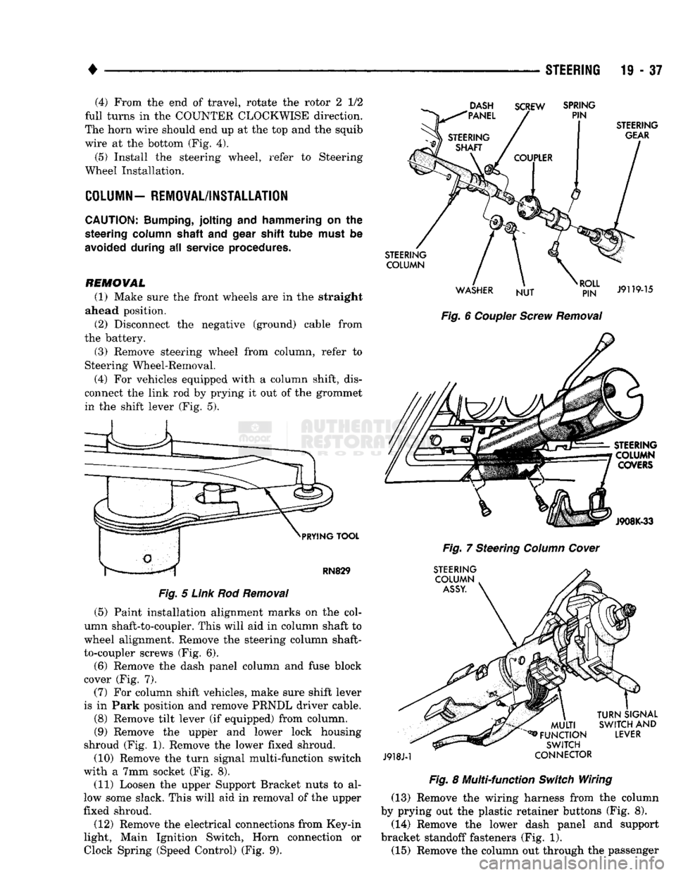
(4) For vehicles equipped with a column shift, dis
connect the link rod by prying it out of the grommet in the shift lever (Fig. 5).
DASH
"PANEL SCREW
SPRING
PIN
PRYING
TOOL
RN829
Fig.
5
Link
Rod
Removal
(5) Paint installation alignment marks on the col
umn shaft-to-coupler. This will aid in column shaft to
wheel alignment. Remove the steering column shaft-
to-coupler screws (Fig. 6).
(6) Remove the dash panel column and fuse block
cover (Fig. 7).
(7) For column shift vehicles, make sure shift lever
is in Park position and remove PRNDL driver cable.
(8) Remove tilt lever (if equipped) from column.
(9) Remove the upper and lower lock housing
shroud (Fig. 1). Remove the lower fixed shroud.
(10) Remove the turn signal multi-function switch
with a 7mm socket (Fig. 8). (11) Loosen the upper Support Bracket nuts to al
low some slack. This will aid in removal of the upper
fixed shroud.
(12) Remove the electrical connections from Key-in
light, Main Ignition Switch, Horn connection or
Clock
Spring (Speed
Control)
(Fig. 9).
STEERING
GEAR
STEERING COLUMN
WASHER NUT
RJ?N"
J9119-15
Fig.
6
Coupler
Screw
Removal
STEERING COLUMN COVERS
J908K-33
Fig.
7 Steering
Column
Cover
STEERING COLUMN
ASSY.
J918J-1
MULTI
^FUNCTION
SWITCH
CONNECTOR
TURN
SIGNAL
SWITCH
AND
LEVER
Fig.
8 Multi-function
Switch
Wiring (13) Remove the wiring harness from the column
by prying out the plastic retainer buttons (Fig. 8).
(14) Remove the lower dash panel and support
bracket standoff fasteners (Fig. 1). (15) Remove the column out through the passenger
Page 1450 of 1502

•
HEATING
AND AIR
CONDITIONING
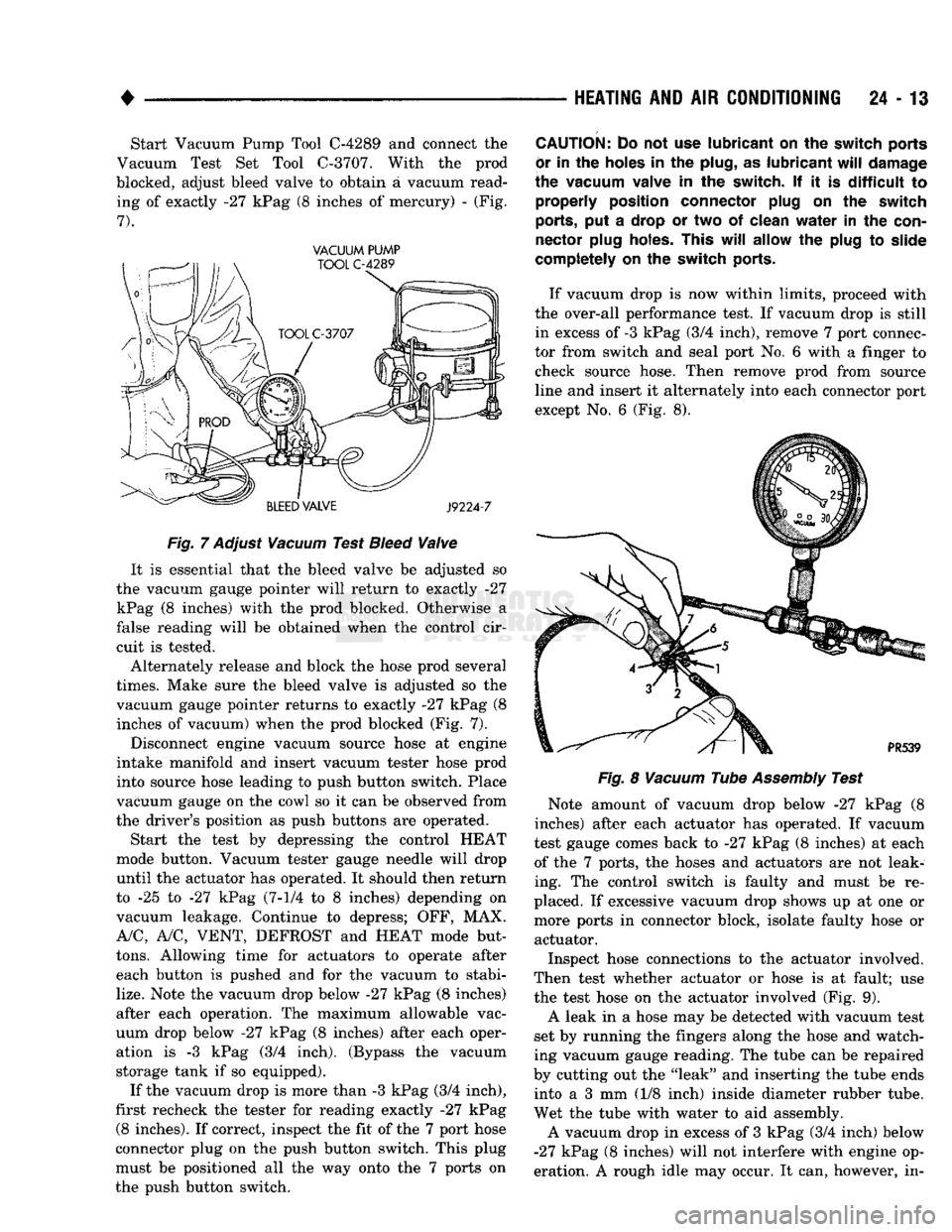
24 - 13 Start Vacuum Pump Tool
C-4289
and connect the
Vacuum Test Set Tool
C-3707.
With the prod
blocked, adjust bleed valve to obtain a vacuum read ing of exactly -27 kPag (8 inches of mercury) - (Fig.
7).
VACUUM PUMP
Fig.
7
Adjust
Vacuum
Test
Bleed
Valve
It is essential that the bleed valve be adjusted so
the vacuum gauge pointer will return to exactly -27 kPag (8 inches) with the prod blocked. Otherwise a
false reading will be obtained when the control cir
cuit is tested.
Alternately release and block the hose prod several
times.
Make sure the bleed valve is adjusted so the vacuum gauge pointer returns to exactly -27 kPag (8 inches of vacuum) when the prod blocked (Fig. 7).
Disconnect engine vacuum source hose at engine
intake manifold and insert vacuum tester hose prod
into source hose leading to push button switch. Place
vacuum gauge on the cowl so it can be observed from
the driver's position as push buttons are operated.
Start the test by depressing the control HEAT
mode button. Vacuum tester gauge needle will drop
until the actuator has operated. It should then return
to -25 to -27 kPag
(7-1/4
to 8 inches) depending on
vacuum leakage. Continue to depress; OFF, MAX.
A/C,
A/C,
VENT,
DEFROST
and
HEAT
mode but
tons.
Allowing time for actuators to operate after each button is pushed and for the vacuum to stabi
lize.
Note the vacuum drop below -27 kPag (8 inches)
after each operation. The maximum allowable vac
uum drop below -27 kPag (8 inches) after each oper ation is -3 kPag (3/4 inch). (Bypass the vacuum
storage tank if so equipped).
If the vacuum drop is more than -3 kPag (3/4 inch),
first recheck the tester for reading exactly -27 kPag
(8
inches). If correct, inspect the fit of the 7 port hose
connector plug on the push button switch. This plug
must be positioned all the way onto the 7 ports on
the push button switch.
CAUTION:
Do not use
lubricant
on the
switch ports
or
in the
holes
in the
plug,
as
lubricant
will
damage
the vacuum valve
in the
switch.
If it is
difficult
to
properly position connector plug
on the
switch
ports,
put a
drop
or two of
clean
water
in the
con
nector plug holes. This
will
allow
the
plug
to
slide
completely
on the
switch ports.
If vacuum drop is now within limits, proceed with
the over-all performance test. If vacuum drop is still in excess of
-3
kPag (3/4 inch), remove 7 port connec
tor from switch and seal port No. 6 with a finger to check source hose. Then remove prod from source
line and insert it alternately into each connector port
except No. 6 (Fig. 8).
Fig.
8
Vacuum
Tube
Assembly
Test
Note amount of vacuum drop below -27 kPag (8
inches) after each actuator has operated. If vacuum
test gauge comes back to -27 kPag (8 inches) at each of the 7 ports, the hoses and actuators are not leak
ing. The control switch is faulty and must be re
placed. If excessive vacuum drop shows up at one or
more ports in connector block, isolate faulty hose or actuator.
Inspect hose connections to the actuator involved.
Then test whether actuator or hose is at fault; use
the test hose on the actuator involved (Fig. 9).
A leak in a hose may be detected with vacuum test
set by running the fingers along the hose and watch
ing vacuum gauge reading. The tube can be repaired
by cutting out the "leak" and inserting the tube ends into a 3 mm (1/8 inch) inside diameter rubber tube.
Wet the tube with water to aid assembly.
A vacuum drop in excess of 3 kPag (3/4 inch) below
-27
kPag (8 inches) will not interfere with engine op
eration. A rough idle may occur. It can, however, in-