1993 DODGE TRUCK drain bolt
[x] Cancel search: drain boltPage 70 of 1502
•
FRONT
SUSPENSION
AND
AXLE
2 - 17
MODEL
44
FRONT
AXLE
INDEX
page
Axle Shaft
and
U-Joint
Service
23
Complete Axle Removal/Installation
31
Differential
Assembly
35
Differential
Disassembly
. 32
Drain
and Refill
19
General
Information
17
Hub,
Spindle
and
Axle Shaft
20
Intermediate
Axle Shaft
30
Lubricant
17
GENERAL
INFORMATION
Model
44
front axles
(Fig. 1)
consists
of an
iron
center casting with axle shaft tubes extending from
either side. The integral type housing, hypoid gear design
has
the centerline
of the
pinion
set
below
the
centerline of
the
ring gear. The axle shaft disconnect housing
is
welded
to the
left axle shaft tube.
A
splined, two-piece axle shaft
is
located
on the
left side
and it is
engaged
or
disen
gaged
by a
shift collar.
The
collar
is
moved
by a
shift
fork controlled
by a
vacuum shift motor.
The
shift motor
is
operated
by
engine vacuum controlled
by a
switch located
at the
transfer case. The axles
are
equipped with full-floating axle
shafts,
meaning that loads
are
supported
by the
spin
dles attached
to the
steering knuckles. The removable, stamped steel cover provides
a
means
for
inspection
and
service without removing
the complete axle from
the
vehicle.
page
Pinion Gear Depth Measurement
and
Adjustment
with
Tool
Set
C-3715-B
40
Pinion Gear Depth Measurement
and
Adjustment
with
Tool
Set
D-115-44
... 38
Pinion Shaft Seal
19
Specifications
48
Steering Knuckle
Arm
31
Steering Knuckle, Upper
and
Lower Ball Studs
. . 24
Vacuum
Shift Motor
26
A small, stamped metal axle gear ratio identifica
tion
tag is
attached
to the
housing cover
via one of
the cover bolts. This
tag
also identifies
the
number
of
ring gear
and
pinion gear teeth.
The differential case
is a
one-piece design.
The dif
ferential pinion mate shaft
is
retained with
a
roll
pin. Differential bearing preload
and
ring gear back lash
are
adjusted
by the use of
shims located between
the differential bearing cones
and
case.
LUBRICANT
Multi-purpose
API GL 5
quality hypoid gear lubri
cant should
be
used
for
Model
44
axles. MOPAR
Hy
poid Gear Lubricant conforms with these specifications
and is
recommended.
CAUTION:
If a
front axle
is
submerged
in
water,
the
axle lubricant must
be
replaced immediately.
Page 72 of 1502
FRONT
SUSPENSION
AND
AXLE
2 - 19
DRAIN
AND
REFILL
(1) Drive the vehicle until the gear lubricant
reaches normal operating temperature. (2) Raise and support the vehicle.
(3) Remove the lubricant fill hole plug from the
differential housing cover.
(4) Remove the differential housing cover. Allow
the original lubricant to completely drain from the
housing and axle shaft tubes.
(5) With standard differential, clean the differen
tial and the housing cavity with a flushing oil (or light engine oil). This will remove the residual lubricant and foreign matter. Do not use water, steam,
kerosene or gasoline for flushing. (6) Scrape the residual gasket from the housing
and cover mating surfaces. Clean the mating sur
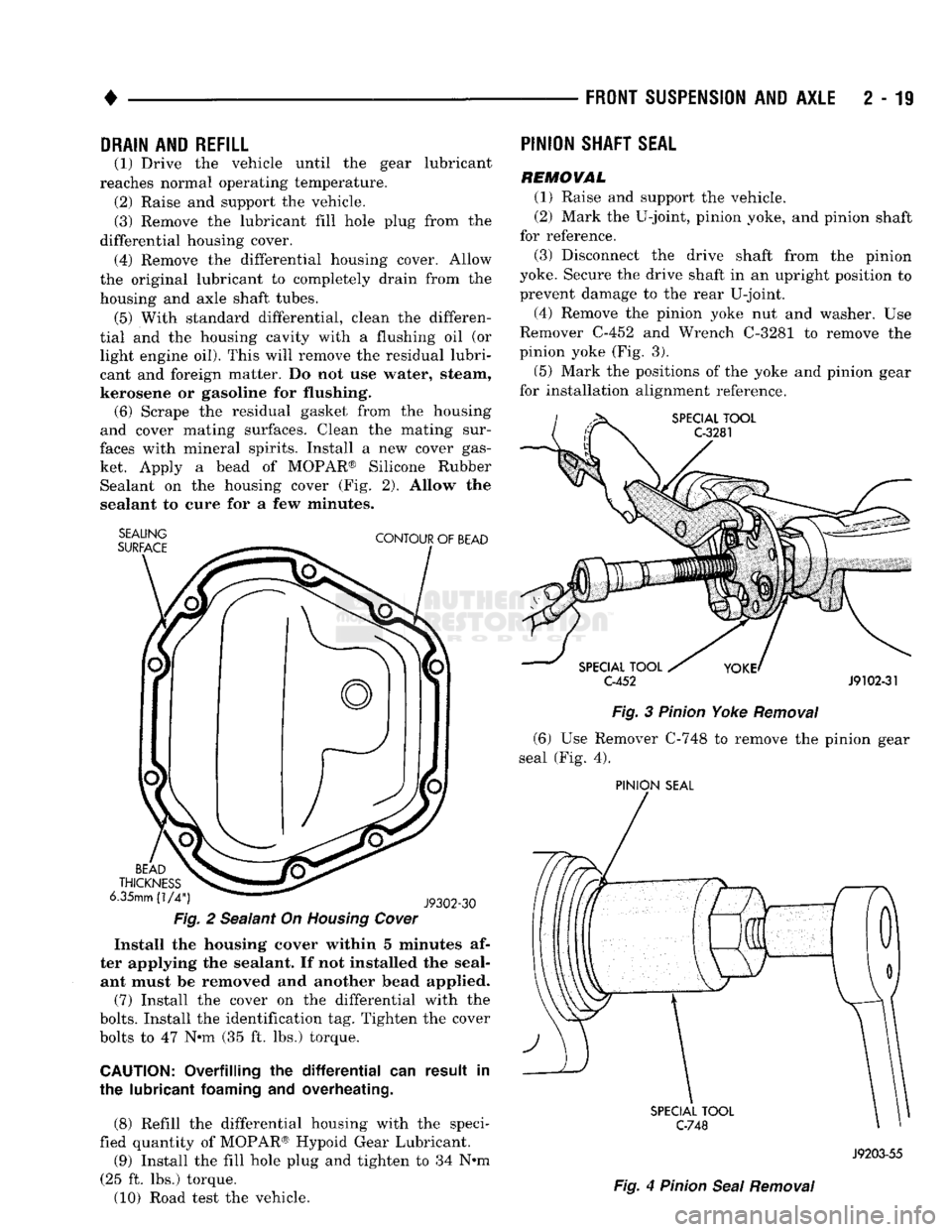
faces with mineral spirits. Install a new cover gas ket. Apply a bead of MOPAR® Silicone Rubber Sealant on the housing cover (Fig. 2). Allow the
sealant to cure for a few minutes.
SEALING
SURFACE
CONTOUR
OF
BEAD
BEAD
THICKNESS
6.35mm
(1/4")
J9302-30
Fig.
2 Sealant On
Housing
Cover
Install the housing cover within 5 minutes af
ter applying the sealant. If not installed the seal ant must be removed and another bead applied.
(7) Install the cover on the differential with the
bolts.
Install the identification tag. Tighten the cover
bolts to 47 Nnn (35 ft. lbs.) torque.
CAUTION:
Overfilling the
differential
can result in
the lubricant
foaming
and overheating.
(8) Refill the differential housing with the speci
fied quantity of MOPAR® Hypoid Gear Lubricant.
(9) Install the fill hole plug and tighten to 34 N#m
(25 ft. lbs.) torque.
(10) Road test the vehicle.
PINION
SHAFT
SEAL
REMOVAL
(1) Raise and support the vehicle.
(2) Mark the U-joint, pinion yoke, and pinion shaft
for reference.
(3) Disconnect the drive shaft from the pinion
yoke. Secure the drive shaft in an upright position to prevent damage to the rear U-joint.
(4) Remove the pinion yoke nut and washer. Use
Remover C-452 and Wrench C-3281 to remove the
pinion yoke (Fig. 3).
(5) Mark the positions of the yoke and pinion gear
for installation alignment reference.
SPECIAL
TOOL
C-3281
SPECIAL
TOOL
C-452
J9102-31
Fig.
3
Pinion
Yoke
Removal
(6) Use Remover C-748 to remove the pinion gear
seal (Fig. 4).
PINION
SEAL
SPECIAL
TOOL
C-748
Fig.
4
Pinion
Seal
Removal
J9203-55
Page 83 of 1502
2
- 30
FRONT
SUSPENSION
AND
AXLE
• REMOVAUDISASSEMBL
Y
(1) Raise and support the vehicle.
(2) Disconnect the vacuum and wiring connector
from the shift housing. (3) Remove the shift motor housing cover, gasket
and shield from the housing.
(4) Remove the E-clips from the shift motor hous
ing and shaft. Remove shift motor and shift fork
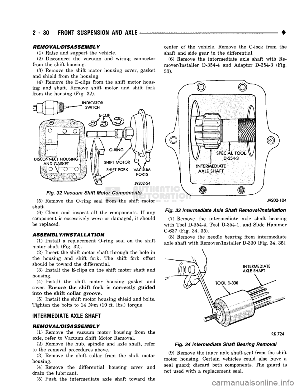
from the housing (Fig. 32).
Fig.
32
Vacuum
Shift Motor
Components
(5) Remove the O-ring seal from the shift motor
shaft. (6) Clean and inspect all the components. If any
component is excessively worn or damaged, it should
be replaced.
ASSEMBL Y/IHSTALLA TION (1) Install a replacement O-ring seal on the shift
motor shaft (Fig. 32). (2) Insert the shift motor shaft through the hole in
the housing and shift fork. The shift fork offset should be toward the differential.
(3) Install the E-clips on the shift motor shaft and
housing.
(4) Install the shift motor housing gasket and
cover. Ensure the shift fork is correctly guided
into the shift collar groove.
(5) Install the shift motor housing shield and bolts.
Tighten the bolts to 14 N*m (10 ft. lbs.) torque.
INTERMEDIATE AXLE SHAFT
REMOVAL/DISASSEMBLY (1) Remove the vacuum motor housing from the
axle,
refer to Vacuum Shift Motor Removal.
(2) Remove the hub, spindle and axle shaft, refer
to the removal procedures above.
(3) Remove the shift collar from the shift motor
housing.
(4) Remove the differential housing cover and
drain the lubricant.
(5) Push the intermediate axle shaft toward the center of the vehicle. Remove the C-lock from the
shaft and side gear in the differential.
(6) Remove the intermediate axle shaft with Re
mover/Installer D-354-4 and Adaptor D-354-3 (Fig.
33).
J9202-104
Fig.
33
intermediate
Axle Shaft Removal/Installation
(7) Remove the intermediate axle shaft bearing
with Tool D-354-4, Tool
D-354-1,
and Slide Hammer C-637 (Fig. 34, 35).
(8) Remove the needle bearing from intermediate
axle shaft with Remover/Installer D-330 (Fig. 34, 35).
RK724
Fig.
34
Intermediate
Shaft Bearing
Removal
(9) Remove the inner axle shaft seal from the shift
motor housing. Certain vehicles could also have a
seal guard; discard both components. The guard is
not used with a replacement seal.
Page 102 of 1502
•
FRONT
SUSPENSION
AND
AXLE
2 - 49
MODEL
60 FRONT
AXLE
INDEX
page
Axle Shaft
and
U-Joint
Service
55
Complete Axle Removal/Installation
59
Differential
Assembly
63
Differential
Disassembly
59
Drain
and Refill
51
General
Information
49
Locking
Hubs,
Spindle
and
Axle Shaft
52
Lubricant
51
page
Pinion Gear Depth Measurement
and
Adjustment
with
Tool
Set
C-758-D6
68
Pinion Gear Depth Measurement
and
Adjustment
with
Tool
Set
D-116
66
Pinion Shaft Seal
51
Specifications
75
Steering Knuckle, Upper
and
Lower Kingpins
. . . 56
GENERAL
INFORMATION
Model
60
front axles
(Fig. 1)
consist
of an
iron cen
ter casting with axle shaft tubes extending from
ei
ther side.
The
tubes
are
pressed into
and
welded
to
the differential housing. The integral type housing, hypoid gear design
has
the centerline
of the
pinion
set
below
the
centerline of
the
ring gear. The axles
are
equipped with full-floating axle
shafts,
meaning that loads
are
supported
by the
spin
dles attached
to the
steering knuckles.
Two
tapered
opposed roller bearings allow
the hub and
rotor
as
sembly
to
rotate
on the
spindle. The removable, stamped steel cover provides
a
means
for
inspection
and
service without removing
the complete axle from
the
vehicle.
A small, stamped metal axle gear ratio identifica
tion
tag is
attached
to the
housing cover
via one of
the cover bolts. This
tag
also identifies
the
number
of
ring gear
and
pinion gear teeth.
The differential case
is a
one-piece design.
The dif
ferential pinion mate shaft
is
retained with
a
roll
pin. Differential bearing preload
and
ring gear back lash
are
adjusted
by the use of
shims located between
the differential bearing cones
and
case.
Page 104 of 1502
FRONT
SUSPENSION
AND
AXLE
2 - 51
LUBRICANT
Multi-purpose API GL 5 quality hypoid gear lubri
cant should be used for Model 60 axles. MOPAR Hy
poid Gear Lubricant conforms to these specifications and is recommended.
CAUTION:
If a front axle is
submerged
in
water,
the
axle lubricant
must
be replaced immediately.
DRAIN AND REFILL
(1) Drive the vehicle until the gear lubricant
reaches normal operating temperature. (2) Raise and support the vehicle.
(3) Remove the lubricant fill hole plug from the
differential housing cover. (4) Remove the differential housing cover. Allow
the original lubricant to completely drain from the
housing and axle shaft tubes. (5) With standard differential, clean the differen
tial and the housing cavity with a flushing oil (or light engine oil). This will remove the residual lubricant and foreign matter. Do not use water, steam,
kerosene or gasoline for flushing. (6) Scrape the residual gasket from the housing
and cover mating surfaces. Clean the mating sur
faces with mineral spirits. Install a new cover gas
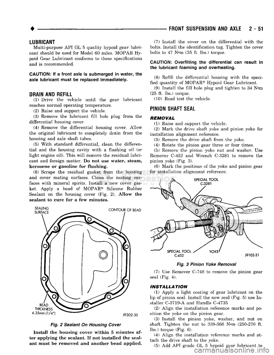
ket. Apply a bead of MOPAR® Silicone Rubber Sealant on the housing cover (Fig. 2). Allow the
sealant to cure for a few minutes.
SEALING
SURFACE
CONTOUR
OF
BEAD
BEAD
THICKNESS
6.35mm (1/4
J9302-30
Fig.
2 Sealant On
Housing
Cover
Install the housing cover within 5 minutes af
ter applying the sealant. If not installed the seal ant must be removed and another bead applied. (7) Install the cover on the differential with the
bolts.
Install the identification tag. Tighten the cover
bolts to 47 Nnn (35 ft. lbs.) torque.
CAUTION:
Overfilling the
differential
can result in
the lubricant
foaming
and overheating.
(8) Refill the differential housing with the speci
fied quantity of MOPAR® Hypoid Gear Lubricant. (9) Install the fill hole plug and tighten to 34 N«m
(25 ft. lbs.) torque. (10) Road test the vehicle.
PINION
SHAFT
SEAL
REMOVAL (1) Raise and support the vehicle.
(2) Mark the drive shaft yoke and pinion yoke for
installation alignment reference.
(3) Remove the drive shaft from the yoke.
(4) Rotate the pinion gear three or four times.
(5) Remove the pinion yoke nut and washer. Use
Remover C-452 and Wrench C-3281 to remove the
pinion yoke (Fig. 3).
(6) Mark the positions of the yoke and pinion gear
for installation alignment reference.
SPECIAL
TOOL
C-3281
SPECIAL
TOOL
C-452
J9102-31
Fig.
3
Pinion
Yoke
Removal
(7) Use Remover C-748 to remove the pinion gear
seal (Fig. 4).
INSTALLATION
(1) Apply a light coating of gear lubricant on the
lip of pinion seal. Install the new seal (Fig. 5) use In
staller C-3719-A and Handle C-4735
(2) Align the installation reference marks and po
sition the yoke on the pinion gear.
(3) Install the pinion yoke, washer, and nut on
shaft. Tighten the nut to 339-366 N-m (250-270 ft.
lbs.) torque (Fig. 6).
(4) Align the installation reference marks and at
tach the drive shaft to the yoke. (5) Add API grade GL 5 hypoid gear lubricant to
Page 139 of 1502
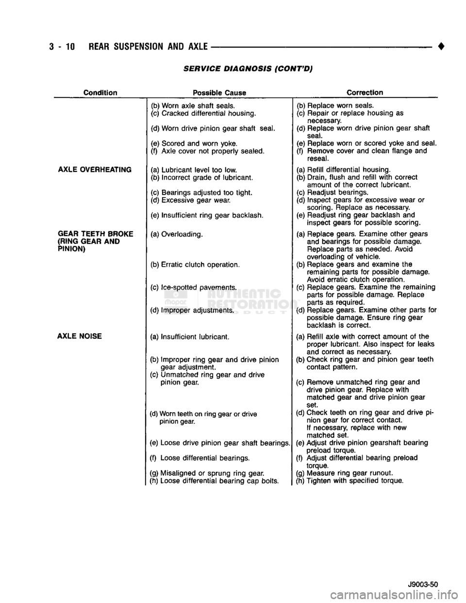
3-10
REAR SUSPENSION
AND
AXLE
SERVICE DIAGNOSIS (CONT'D)
Condition
Possible
Cause
Correction
AXLE OVERHEATING
GEAR TEETH BROKE
(RING GEAR
AND
PINION)
AXLE NOISE
(b) Worn axle
shaft
seals.
(c) Cracked
differential
housing.
(d) Worn
drive
pinion
gear
shaft
seal.
(e) Scored and worn yoke.
(f) Axle cover not
properly
sealed.
(a)
Lubricant
level
too low. (b)
Incorrect
grade of
lubricant.
(c) Bearings
adjusted
too
tight.
(d) Excessive gear wear.
(e)
Insufficient
ring
gear backlash,
(a) Overloading.
(b)
Erratic
clutch
operation.
(c) Ice-spotted pavements.
(d) Improper adjustments.
(a)
Insufficient
lubricant.
(b) Improper
ring
gear and
drive
pinion
gear
adjustment.
(c) Unmatched
ring
gear and
drive
pinion
gear.
(d) Worn
teeth
on
ring
gear or
drive
pinion
gear.
(e) Loose
drive
pinion
gear
shaft
bearings.
(f) Loose
differential
bearings.
(g) Misaligned or sprung
ring
gear.
(h) Loose
differential
bearing cap bolts. (b) Replace worn
seals.
(c) Repair or replace housing as
necessary.
(d) Replace worn
drive
pinion
gear
shaft
seal.
(e) Replace worn or scored yoke and seal.
(f) Remove cover and clean flange and reseal.
(a)
Refill
differential
housing. (b) Drain,
flush
and
refill
with
correct
amount of the
correct
lubricant.
(c) Readjust bearings.
(d) Inspect gears for excessive wear or scoring. Replace as necessary.
(e) Readjust
ring
gear backlash and inspect gears for possible scoring.
(a) Replace gears. Examine
other
gears and bearings for possible damage. Replace parts as needed. Avoid
overloading of vehicle.
(b) Replace gears and examine the remaining parts for possible damage.
Avoid
erratic
clutch
operation.
(c) Replace gears. Examine the remaining parts for possible damage. Replace
parts as required.
(d) Replace gears. Examine
other
parts for possible damage. Ensure
ring
gear
backlash is
correct.
(a)
Refill
axle
with
correct
amount of the proper
lubricant.
Also inspect for leaks
and
correct
as necessary.
(b) Check
ring
gear and
pinion
gear
teeth
contact
pattern.
(c) Remove unmatched
ring
gear and
drive
pinion
gear. Replace
with
matched gear and
drive
pinion
gear
set.
(d) Check
teeth
on
ring
gear and
drive
pi nion gear for
correct
contact.
If necessary, replace
with
new
matched set.
(e) Adjust
drive
pinion
gearshaft bearing preload
torque.
(f) Adjust
differential
bearing preload
torque.
(g) Measure
ring
gear
runout.
(h) Tighten
with
specified
torque.
J9003-50
Page 140 of 1502
•
REAR
SUSPENSION
AND
AXLE
3 - 11 8 3/8 and 9 1/4
AXLE
INDEX
page
Axle Shaft, Seal
and
Bearing Service
......... 11
Complete Axle Removal/Installation
16
Differential
Service
16
Information
11
INFORMATION
The 8 3/8 and 9 1/4 axle (Fig. 1) housing consist of
a cast iron center section. They also have two steel
axle shaft tubes that are pressed into and welded to
the differential housing. The removable, stamped steel cover provides a
means for inspection and service without removing
the complete axle from the vehicle.
LUBRICANT
Multi-purpose, hypoid gear lubricant should be
used for 8 3/8 and 9 1/4 axles. The lubricant should
have MIL-L-2105C and API GL 5 quality specifica
tions.
MOPAR® Hypoid Gear Lubricant conforms to
both of these specifications.
Refer to Group 0, Lubrication and Maintenance for
additional information.
CAUTION:
If a
rear axle
is
submerged
in
water,
the
axle lubricant must
be
replaced immediately.
DRAIN
AND
REFILL
(1) Drive the vehicle until the gear lubricant
reaches normal operating temperature.
(2) Raise and support the vehicle.
(3) Remove the lubricant fill hole plug from the
differential housing cover.
(4) Remove the differential housing cover. Allow
the original lubricant to completely drain from the
housing and axle shaft tubes. (5) With standard differential, clean the differen
tial and the housing cavity with a flushing oil (or light engine oil). This will remove the residual lubri
cant and foreign matter.Do not use water, steam,
kerosene or gasoline for flushing.
CAUTION:
DO NOT
FLUSH
Sure-Grip differentials.
Sure-Grip
differentials
may be
cleaned only
by
wip
ing
with
clean,
lint-free
cloths.
(6)
Scrape the residual sealant from the housing
and cover mating surfaces. Clean the mating sur
faces with mineral spirits. Apply a bead of MOPAR® Silicone Rubber Sealant on the housing cover (Fig.
2).
Allow the sealant to cure for a few minutes.
page
Lubricant
11
Pinion Depth Measurement
and
Adjustment
with
Gauge
Set 20
Pinion
Seal
Replacement
14
Install the housing cover within 5 minutes af
ter applying the sealant. If not installed, the sealant must be removed and another bead ap
plied. (7) Install the cover on the differential. Install the
identification tag. Tighten the cover bolts to 47 N#m (35 ft. lbs.) torque.
CAUTION:
Overfilling
the
differential
can
result
in
the lubricant foaming
and
overheating.
(8) Refill the differential with the specified quan
tity of MOPAR® Hypoid Gear Lubricant. With Sure- Grip differentials, add a container of MOPAR®
Hypoid Gear Lubricant Additive.
(9) Install the fill hole plug.
(10) Road test the vehicle.
AXLE
SHAFT, SEAL AND BEARING
SERVICE
CAUTION:
When rear axle service
is
necessary, both rear wheels must
be
raised
off the
surface
so
that
they
are
free
to
rotate.
Be
cautious when
the
tires
are
being rotated
by the
engine
or by
other
means.
CAUTION:
If
equipped
with
a
Sure-Grip
differential,
do
not
rotate
either
axle shaft unless both
are
prop
erly
in-place. Rotation
of one
axle shaft without
the
other being installed
can
result
in
misalignment
of
the side gears/splines. This
will
necessitate side
gear
re-alignment before
the
axle shaft
can be in
stalled.
AXLE SHAFT REMOVAL
(1) Raise and support the vehicle.
(2) Remove the wheel.
(3) Remove the brake drum.
(4) Clean all the foreign material from housing
cover area.
(5) Loosen the housing cover bolts. Drain the lubri
cant from the housing. Remove the housing cover.
(6)
Rotate the differential case so the pinion mate
gear shaft lock screw is accessible. Remove the lock screw and the pinion mate gear shaft from the case (Fig. 3).
Page 143 of 1502
3
- 14
REAR SUSPENSION
AND
AXLE
3
- 18
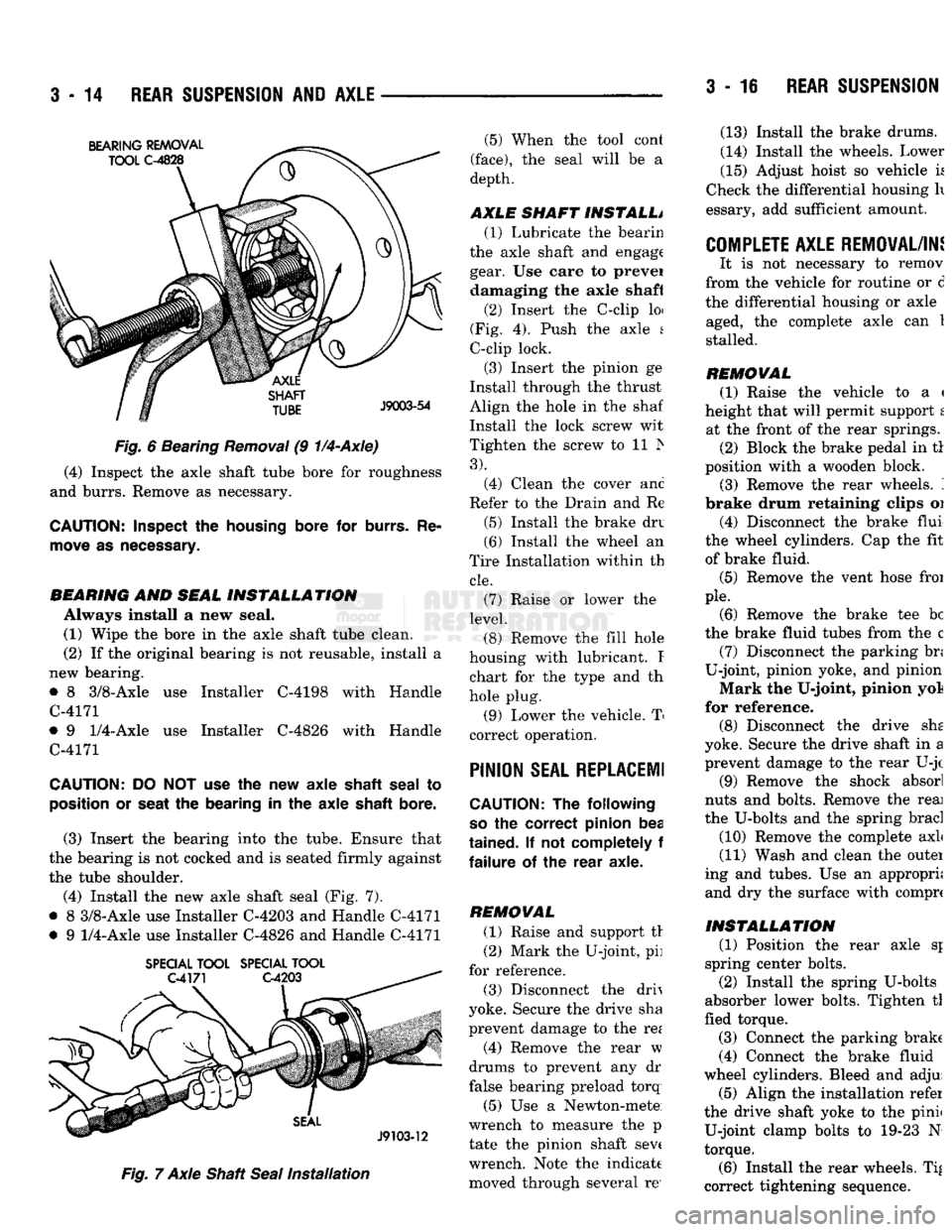
REAR SUSPENSION Fig.
6 Bearing
Removal
(9
1/4-Axle)
(4) Inspect the axle shaft tube bore for roughness
and burrs. Remove as necessary.
CAUTION:
Inspect
the
housing
bore for
burrs.
Re
move
as
necessary.
BEARING
AND
SEAL
INSTALLATION
Always install a new seal. (1) Wipe the bore in the axle shaft tube clean.
(2) If the original bearing is not reusable, install a
new bearing.
• 8 3/8-Axle use Installer C-4198 with Handle
C-4171
• 9
1/4-Axle
use Installer C-4826 with Handle
C-4171
CAUTION:
DO NOT use the new axle
shaft
seal
to
position
or
seat
the bearing in the axle
shaft
bore.
(3) Insert the bearing into the tube. Ensure that
the bearing is not cocked and is seated firmly against
the tube shoulder.
(4) Install the new axle shaft seal (Fig. 7).
• 8 3/8-Axle use Installer C-4203 and Handle C-4171
• 9
1/4-Axle
use Installer C-4826 and Handle C-4171
SPECIAL
TOOL
SPECIAL
TOOL
Fig.
7 Axle Shaft
Seal
Installation
(5) When the tool cont
(face),
the seal will be a
depth.
AXLE SHAFT INSTALL* (1) Lubricate the bearin
the axle shaft and engage gear. Use care to prevei damaging the axle shaft
(2) Insert the C-clip loi
(Fig. 4). Push the axle s
C-clip lock.
(3) Insert the pinion ge
Install through the thrust
Align the hole in the shaf
Install the lock screw wit
Tighten the screw to 11 Is
3).
(4) Clean the cover anc
Refer to the Drain and Re
(5) Install the brake drv
(6) Install the wheel an
Tire Installation within th
cle.
(7) Raise or lower the
level.
(8) Remove the fill hole
housing with lubricant. I chart for the type and th
hole plug.
(9) Lower the vehicle. T
correct operation.
PINION
SEAL REPLACE!!
CAUTION:
The following
so
the correct pinion bea
tained.
If not completely f
failure
of the rear axle.
REMOVAL (1) Raise and support tr
(2) Mark the U-joint, pi]
for reference.
(3) Disconnect the drh
yoke. Secure the drive sha
prevent damage to the re*
(4) Remove the rear w
drums to prevent any dr
false bearing preload torq
(5) Use a Newton-mete
wrench to measure the p
tate the pinion shaft sev( wrench. Note the indicate moved through several re' (13) Install the brake drums.
(14) Install the wheels. Lower
(15) Adjust hoist so vehicle k
Check the differential housing h
essary, add sufficient amount.
COMPLETE AXLE REMOVAL/IN!
It is not necessary to remov
from the vehicle for routine or d
the differential housing or axle aged, the complete axle can 1
stalled.
REMOVAL (1) Raise the vehicle to a <
height that will permit support t at the front of the rear springs. (2) Block the brake pedal in tl
position with a wooden block. (3) Remove the rear wheels. '.
brake drum retaining clips oi
(4) Disconnect the brake flui
the wheel cylinders. Cap the fit of brake fluid.
(5) Remove the vent hose froi
pie.
(6) Remove the brake tee be
the brake fluid tubes from the c (7) Disconnect the parking bn
U-joint, pinion yoke, and pinion
Mark the U-joint, pinion yol
for reference. (8) Disconnect the drive she
yoke. Secure the drive shaft in a prevent damage to the rear U-jc
(9) Remove the shock absorl
nuts and bolts. Remove the reai
the U-bolts and the spring brad
(10) Remove the complete axL
(11) Wash and clean the outei
ing and tubes. Use an appropri; and dry the surface with comprc
INSTALLATION
(1) Position the rear axle sj
spring center bolts.
(2) Install the spring U-bolts
absorber lower bolts. Tighten tl
fled torque.
(3) Connect the parking brake
(4) Connect the brake fluid
wheel cylinders. Bleed and adjui (5) Align the installation refer
the drive shaft yoke to the pinii U-joint clamp bolts to 19-23 N
torque.
(6) Install the rear wheels. Ti|
correct tightening sequence.