1993 DODGE TRUCK adding oil
[x] Cancel search: adding oilPage 31 of 1502

0 - 12
LUBRICATION
AND
MAINTENANCE
• A vehicle equipped with SAE approved sling-type
towing equipment can be used (Fig. 10). However,
many vehicles are equipped with air dams, spoilers, and/or ground effect panels. In this case a wheel-lift
towing vehicle or a flat-bed hauling vehicle is recom mended (Fig. 10). If a flat bed device is used, the ap
proach angle should not exceed 15 degrees.
GROUND CLEARANCE The lifted wheels of the disabled vehicle should be
a minimum of 10 cm (4 in.) off the ground. Make
sure there is enough clearance at the opposite end.
This is critical when towing over rough terrain. If necessary, the rear ground clearance can be increased by removing the wheels from the lifted end
and then towing with the lifted end closer to the
ground. If the rear wheels are removed, secure the
brake drums. A 20 cm (8 in.) ground clearance must
be maintained between brake drums or rotors and the ground.
SAFETY PRECAUTIONS The following safety precautions must be consid
ered when preparing for and during a vehicle towing operation:
• Remove exhaust pipe tips that interfere with the
tow sling and crossbar • Padding should be placed between the tow sling/
crossbar and any painted surfaces
• If the vehicle is damaged, secure the loose and pro
truding parts
• Always use a safety chain system that is indepen dent of the lifting and towing equipment
• When placing tow hooks on the rear axle, position them so they do not damage the brake tubing or
hoses
• Do not allow any of the towing equipment to con
tact the fuel tank
• Do not tow the vehicle by connecting to the front
or rear shock absorbers
• The operator should not go under a vehicle while
it is lifted by the towing equipment. The vehicle
should first be supported by safety stands
• Do not allow passengers in a vehicle being towed
• Observe all state and local laws involving warning signals, night illumination, speed, etc.
• Do not exceed a towing speed of 48 km/h (30 mph)
• Avoid towing distances of more than 24 km (15
miles) whenever possible • Do not attach tow chains or a tow sling to a
bumper, the steering linkage, the universal joints, or a drive shaft
REAR-END RAISED TOWING It is recommended that the rear-end raised towing
method be used. Vehicles can be towed with the front
wheels on the ground for extended distances at speeds not exceeding 48 km/h (30 mph) (Fig. 11). (1) Attach the J-hooks around the axle shaft tubes
outboard of the rear springs. (2) Position and center the sling under and for
ward of the rear bumper. (3) Attach safety chains (with pads) at each end of
the rear bumper.
(4) Turn the ignition switch to the OFF position to
unlock the steering wheel. (5) Clamp the steering wheel with the front wheels
in the straight ahead position.
CAUTION:
Do not use the steering
column
lock
to
secure
front
wheel
in the straight-ahead
position.
(6) Shift the transmission to NEUTRAL.
POSITION CENTER BAR FORWARD
OF
BUMPER
-
/
J-HOOKS OUTBOARD
OF
SPRINGS
RN967A
Fig. 11 Rear-End
Raised
Towing
FRONT'END RAISED TOWING If a vehicle cannot be towed from the rear, the
front-end raised towing method normally can be
used (Fig. 12). (1) Center the sling with the bumper and position
it at the frame front crossmember.
CAUTION:
Use tow
chains
with
J-hooks
for
con
necting
to the
disabled
vehicle's
lower
suspension
arms.
Never use
T-hooks.
(2) Route the J-hooks and tow chains over the
steering linkage outboard of the coil spring.
(3) Attach the J-hooks to the outer end of the
lower suspension arms.
(4) Raise the vehicle.
(5.) Attach the safety chains to the disabled vehicle
at the frame rails.
Vehicles equipped with a MANUAL TRANSMIS
SION can be towed with the rear wheels on the
Page 50 of 1502

•
LUBRICATION
AND
MAINTENANCE
0 - 31
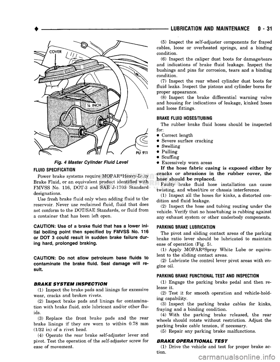
Fig. 4 Master Cylinder Fluid Level
FLUID
SPECIFICATION
Power brake systems require MOP AR®Heavy-D uty
Brake Fluid, or an equivalent product identified with
FMVSS No. 116, DOT-3 and SAE J-1703 Standard designations. Use fresh brake fluid only when adding fluid to the
reservoir. Never use reclaimed fluid, fluid that does not conform to the DOT/SAE Standards, or fluid from a container that has been left open.
CAUTION:
Use of a
brake fluid that
has a
lower ini
tial
boiling point then specified
by
FMVSS
No. 116
or
DOT 3
could result
in
sudden brake failure dur
ing
hard, prolonged braking.
CAUTION:
Do not
allow petroleum base
fluids
to
contaminate
the
brake fluid. Seal damage
will
re
sult.
BRAKE SYSTEM INSPECTION (1) Inspect the brake pads and linings for excessive
wear, cracks and broken rivets.
(2) Inspect brake pads and linings for contamina
tion with brake fluid, axle lubricant and/or other flu
ids.
(3) Replace the front brake pads and the rear
brake linings if they are worn to within 0.78 mm (1/32 in) of a rivet head.
(4) Operate the rear brake self-adjuster lever and
pivot. Test the operation of the self-adjuster screw for ease of movement. (5) Inspect the self-adjuster components for frayed
cables, loose or overheated springs, and a binding
condition.
(6) Inspect the caliper dust boots for damage/tears
and indications of brake fluid leakage. Inspect the
bushings and pins for corrosion, tears and a binding condition.
(7) Inspect the rear wheel cylinder dust boots for
fluid leaks. Inspect the pistons and cylinder bores for
proper appearance. (8) Inspect the brake differential warning valve
and housing for indications of leakage, kinked hoses and loose fittings.
BRAKE
FLUID
HOSES/TUBING
The rubber brake fluid hoses should be inspected
for:
• Correct length
• Severe surface cracking
• Swelling
• Pulling
• Scuffing
• Excessively worn areas If the hose fabric casing is exposed either by
cracks or abrasions in the rubber cover, the
hose should be replaced.
Faulty brake fluid hose installation can cause
twisting, and wheel/tire or chassis interference.
(1) Inspect all the hoses for kinks, a distorted con
dition and fluid leakage. (2) Inspect the hose and tubing routing under the
vehicle. Verify that no hose/tubing is rubbing against any exhaust system or other underbody components.
PARKING
BRAKE
LUBRICATION
The pivot and sliding contact areas of the parking
brake ratio lever should be lubricated to maintain ease of operation (Fig. 5).
(1) Apply MOPAR®Spray White Lube or equiva
lent to the sliding contact areas.
(2) Lubricate the control lever pivot areas with en
gine oil.
PARKING
BRAKE
FUNCTIONAL
TEST
AND
INSPECTION
(1) Engage the parking brake pedal and then re
lease it. (2) Test it for smooth operation and vehicle-hold
ing capability.
(3) Inspect the parking brake cables for kinks,
fraying and a binding condition. (4) With the parking brake released, the rear
wheels should rotate without restriction. Adjust the
parking brake cable tension, if necessary.
(5) Repair any parking brake malfunctions.
BRAKE OPERATIONAL TEST (1) Drive the vehicle and test for proper brake ac
tion.
Page 298 of 1502

•
COOLING
SYSTEM
7 - 27 down to -67.7°C (-90°F). A higher percentage will
freeze at a warmer temperature. Also, a higher per centage of antifreeze can cause the engine to over
heat because specific heat of antifreeze is lower than
that of water.
CAUTION:
Richer
antifreeze
mixtures
cannot
be
measured
with
normal
field
equipment
and can
cause
problems
associated
with 100
percent
ethyl
ene-glycol.
COOLANT SELECTION-ADDITIVES The presence of aluminum components in the cool
ing system requires strict corrosion protection. Main
tain coolant at specified level with a mixture of ethylene-glycol based antifreeze and water. Only use an antifreeze containing ALUGARD 340-2
™
such as
Mopar Antifreeze. If coolant becomes contaminated
or looses color, drain and flush cooling system and
fill with correctly mixed solution.
A 0.25 percent emulsifiable oil is added to the ra
diator at the factory to prevent solder corrosion.
CAUTION:
Do not use
coolant
additives
that are
claimed
to
improve
engine
cooling.
COOLANT SERVICE-EXCEPT DIESEL It is recommended that the cooling system be
drained and flushed at 84,000 kilometers (52,500
miles) or 3 years, whichever occurs first. Then every
two years or 48,000 kilometers (30,000 miles), which ever occurs first.
COOLANT SERVICE-DIESEL ENGINE It is recommended that the cooling system be
drained and flushed every 24 months or 38,600 kilo meters (24,000 miles), whichever occurs first.
COOLANT LEVEL CHECK-ROUTINE Do not remove radiator cap for routine coolant
level inspections. The coolant level can be checked at the coolant reserve/overflow tank.
The coolant reserve/overflow system provides a
quick visual method for determining the coolant
level without removing the radiator pressure cap.
With engine idling and at normal operating temper ature, observe coolant level in coolant reserve/over
flow tank. The coolant level should be between the MIN and MAX (diesel engine) or ADD and FULL (gas engines) marks.
ADDING ADDITIONAL COOLANT-ROUTINE Do not remove the radiator cap to add coolant
to the system. When adding coolant to maintain the correct level, do so at the coolant reserve/overflow
tank with a 50/50 mixture of ethylene-glycol anti
freeze (containing Alugard 340-2 ™) and water. Re move the radiator cap only for testing or when
refilling the system after service. Removing cap un necessarily can cause loss of coolant and allow air to
enter system. This produces corrosion.
COOLANT LEVEL CHECK-SERVICE The cooling system is closed and designed to main
tain coolant level to the top of the radiator.
WARNING:
DO
NOT OPEN RADIATOR DRAINCOCK
WITH
ENGINE RUNNING
OR
WHILE ENGINE
IS HOT
AND COOLING
SYSTEM
IS
UNDER
PRESSURE.
When vehicle servicing requires a coolant level
check in the radiator, drain several ounces of coolant
from the radiator drain cock. Do this while observing
the coolant reserve/overflow system tank. The cool ant level in the reserve/overflow tank should drop
slightly. If not, inspect for a leak between radiator and coolant reserve/overflow system connection. Re
move radiator cap. The coolant level should be to the
top of the radiator. If not and if coolant level in re serve/overflow tank is at the ADD (gas engines) or
MIN (5.9L diesel engine) mark, check for:
• An air leak in the coolant reserve/overflow tank
• An air leak in the radiator filler neck
• Leak in the pressure cap seal to the radiator filler
neck
LOW COOLANT LEVEL-AERATION If the coolant level in the radiator drops below the
top of the radiator core tubes, air will enter the sys
tem. Low coolant level can cause the thermostat pellet
to be suspended in air instead of coolant. This will cause the thermostat to open later, which in turn causes higher coolant temperature. Air trapped in
cooling system also reduces the amount of coolant
circulating in the heater core. This may result in low
heat output.
DEAERATION As the engine operates, air trapped in the cooling
system gathers under the radiator cap. The next time
engine is operated, thermal expansion of coolant will
push trapped air past radiator cap into coolant re serve/overflow tank. Here it escapes to atmosphere in
the tank. When engine cools down the coolant, it will
be drawn from reserve/overflow tank into radiator to replace removed air.
DRAINING
COOLING
SYSTEM
WARNING:
DO NOT
REMOVE
THE
CYLINDER BLOCK DRAIN PLUGS
OR
LOOSEN THE RADIATOR
DRAIN PLUG
WITH
SYSTEM
HOT AND
UNDER
PRESSURE.
SERIOUS BURNS
FROM
COOLANT
CAN OCCUR.
Page 1454 of 1502

•
HEATING
AND
AIR
CONDITIONING
24-17 REFRIGERANT SYSTEM SERWICE PROCEDURES
INDEX
page
Charging
the
System
19
Correcting
Low
Refrigerant
Level
.............
20
Discharging
the
System
. 19
Evacuating
the
System
19
REFRIGERANT
SAFETY
PRECAUTIONS
WARNING: EXTREME CARE MUST
BE
TAKEN
TO
PREVENT
ANY LIQUID
REFRIGERANT FROM COM
ING
IN
CONTACT
WITH
THE
SKIN
AND
ESPE
CIALLY
THE
EYES.
ALWAYS WEAR SAFETY
GOGGLES WHEN SERVICING
ANY
PART
OF
THE
REFRIGERANT SYSTEM.
IF EYE
CONTACT
IS
MADE,
APPLY
A
FEW
DROPS
OF
MINERAL
OIL
TO
THE
EYES
AND
FLUSH
WITH
WATER
FOR
SEV
ERAL MINUTES.
SEEK
MEDICAL
ATTENTION
IMME
DIATELY.
The refrigerant used
in the air
conditioner system
is Refrigerant-12 (R-12).
R-12 is
nonexplosive, non
flammable, non-corrosive,
has
practically
no
odor
and
is heavier than
air.
Although
it is
classified
as a
safe
refrigerant, certain precautions must
be
observed
to
protect
the
parts involved
and the
person
who is
working
on the
unit. Liquid
R-12, at
normal atmo sphere pressures
and
temperatures, evaporates
so
quickly that
it has the
tendency
to
freeze anything
it
contacts.
WARNING:
TO
AVOID
A
DANGEROUS EXPLOSION,
NEVER
WELD
OR
STEAM CLEAN NEAR
AIR
CON
DITIONING
LINES
OR
COMPONENTS.
DO NOT
HEAT
R-12
ABOVE
52°C (125°F)
BECAUSE
THE
CAN
MAY
EXPLODE.
The
R-12 in the
system
is
always under pressure.
Because
the
system
is
tightly sealed, heat applied
to
any part could cause this pressure
to
build
up
excessively.
WARNING: LARGE AMOUNTS
OF
REFRIGERANT
RELEASED
IN A
CLOSED WORK AREA
WILL
DIS
PLACE
THE
OXYGEN
AND
CAUSE SUFFOCATION.
ALWAYS
MAINTAIN
GOOD
VENTILATION
SUR ROUNDING
THE
WORK AREA.
R-12
gas,
under normal conditions,
is
non-poison
ous.
The
discharge
of R-12 gas
near
an
open flame
page
Pressure Gauge
and
Manifold
Assembly
18
Refrigerant
. 17
Refrigerant
Leak Repair Procedure
20
Service Precautions
. 17
can produce
a
very poisonous
gas
called phosgene.
Phosgene
is
generated when
a
flame-type leak detec
tor
is
used.
CAUTION:
When charging
an A/C
system always
keep
the
tank
in an
upright position.
If the
tank
is
on
its
side
or
upside down,
liquid
refrigerant
will
enter
the
system
and may
damage
the
compressor.
In most instances, moderate heat
is
required
to
bring
the
pressure
of the
refrigerant above system
pressure when charging
or
adding refrigerant.
A
bucket
or
large
pan of hot
water,
not
over 52°C (125°F),
is all the
heat required
for
this purpose.
Do
not heat
the
refrigerant container with
a
blow torch
or
any
other means that would raise
the
temperature and pressure above this temperature.
CAUTION:
Do not
allow
liquid
refrigerant
to
touch
bright
metal.
Refrigerant will tarnish bright metal
and
chrome
surfaces. Avoid splashing
the
refrigerant
on any
sur
face.
Refrigerant
in
combination with moisture
is
very corrosive
and can
cause extensive damage
to all
metal surfaces.
RECYCLING
(R-12) refrigerant
is a
chloroflorocarbon
(CFC)
that
can contribute
to the
depletion
of the
ozone layer
in
the upper atmosphere. Harmful radiation from
the
sun
is
filtered
out by the
ozone.
To
assist
in
protect
ing
the
ozone layer, Chrysler Corporation recom
mends that
an
(R-12) refrigerant recycling device
that meets
SAE
standard
J1991 be
used. Contact
an
automotive service equipment supplier
for
refriger
ant recycling equipment that
is
available
in
your
area. Refer
to the
operating instructions provided
with
the
recycling equipment
for
proper operation.
SERVICE
PRECAUTIONS
Kinks
in the
refrigerant tubing
or
sharp bends
in
the refrigerant hose lines will greatly reduce
the ca
pacity
of the
entire system. High pressures
are
produced
in the
system when
it is
operating. Extreme
care must
be
exercised
to
make sure that
all
connec
tions
are
pressure tight. Dirt
and
moisture
can
enter
Page 1457 of 1502

24
- 20
HEATING
AND AIR
CONDITIONING
• (3) Turn
3
refrigerant manifold valves completely
clockwise
to
puncture
the
cans
and
close
the
mani
fold valves.
(4) Purge
the air
from
the
charging line
by
loosen
ing
the
charging hose
at the
manifold gauge
set and
turn
one of the
refrigerant valves counterclockwise. When
the
refrigerant
gas
starts escaping from
the
loose connection, tighten
the
hose.
(5) Fully open
all 3
refrigerant manifold valves
and place
the
cans
of
refrigerant into
a pan
contain
ing 52°C (125°F) water.
The
water will warm
the
charging
can and aid in the
transfer
of the
charge
into
the
system.
(6) Start
the
engine
and
move
the
controls
to A/C
low blower position.
The electronic temperature cycling switch will pre
vent
the
clutch from engaging until refrigerant
is
added
to the
system.
If the
clutch does engage,
re
place
the
switch before proceeding
any
further. (7) Charge through
the
suction side
of the
system
by slowly opening
the
suction manifold valve. Adjust
the valve
as
necessary
so
charging pressure does
not
exceed
345
kPag
(50
psig). Maintain
the
temperature
of
the
water
in the pan by
adding warm water
as
necessary. (8) Adjust
the
engine speed
to a
fast idle
of
approx
imately
1,300 RPM.
(9) When
all 3
cans
of
refrigerant
are
completely
empty, close
the
manifold gauge
set
valves
and re
frigerant manifold valves. The maximum refrigerant charge
is 44 oz.
REFRIGERANT
LEAK REPAIR PROCEDURE
LOST CHARGE If
the
system
has
lost
all
charge
due to a
leak: (1) Evacuate
the
system.
(2) Charge
the
system with approximately
1
pound
of refrigerant. (3) Locate
all
leaks.
(4) Repair
all
leaks.
(5) Replace filter-drier bottle.
CAUTION:
Replacement
filter-drier
units
must
be
sealed
while
in
storage.
The
drier
used
in
these
units
absorbs
and
traps
moisture
quickly
upon
ex
posure
to the
atmosphere.
When
installing
a
drier,
have
all
tools
and
supplies ready
for
quick
reas
sembly
to
avoid keeping
the
system open
any
longer
than
necessary.
(6) Check system
oil
level. (7) Evacuate
and
charge
the
system.
LOW CHARGE If
the
system
has not
lost
all of its
refrigerant
charge; locate
and
repair
all
leaks.
If it is
necessary
to increase
the
system pressure
to
find
the
leak
(be
cause
of an
especially
low
charge),
add 230 g (1/2 lb)
of refrigerant.
If
there
has
been
a
significant
oil
loss,
check
the
system
oil
level.
If
leak repair
was
possible
without discharging system
and an oil
level check
was
not
necessary,
use
procedure
for
correcting
low
refrigerant level.
CORRECTING
LOW
REFRIGERANT LEVEL
Since
the
refrigeration system
is
completely sealed,
the refrigerant level will
not be low
unless there
is a
leak
in the
system. Before adding refrigerant where
the
cause
of a low
level
is not
known,
the
system should
be
tested
for
leaks.
Assuming that leaks have been corrected without
discharging
the
system, proceed with partial charge.
Install
and
connect manifold gauge
set.
(1) Close both manifold gauge
set
valves. Open
manifold gauge
set
needle valve.
(2) Connect
the
suction gauge test hose
to the
suc
tion service port
of the
compressor. Connect
the
dis charge gauge test hose
to the
discharge service port. (3) Connect
an end of
long test hose
to the
center
manifold outlet,
and
other
end to
refrigerant dispens ing manifold. (4) Close
the 2
dispensing manifold valves
and
open remaining dispensing manifold valve. Remove
protective
cap
from opened valve.
WARNING: NEVER
USE
THESE CANS
TO
CHARGE
INTO
THE
HIGH
PRESSURE SIDE
OF
THE
SYSTEM
(COMPRESSOR
DISCHARGE
PORT)
OR
INTO
A
SYSTEM
THAT
IS AT
HIGH
TEMPERATURE.
THE
HIGH
SYSTEM PRESSURES COULD
BE
TRANS
FERRED
INTO
THE
CHARGING
CAN
CAUSING
IT
TO EXPLODE.
(5) Screw
a can of R-12 to the
opened manifold
valve.
Be
sure gasket
is in
place
and in
good condi
tion. Tighten refrigerant
can and
manifold locking nut
to
ensure
a
good seal.
Do not
overtighten.
Tighten
to 9.5 N*m (7 ft. lbs.)
torque,
if
gasket
is in
good condition.
(6) Turn manifold valve (above
the
refrigerant
can)
completely clockwise
to
puncture
the can.
This closes
the valve
and
seals
the
refrigerant
in the can.
CAUTION:
Do not
heat refrigerant
12
above
52°C
(125°F).
(7) Place refrigerant
can in a
large
pan of
water
heated
to
52°C (125°F). Place
pan of
water containing
the refrigerant
can on an
accurate scale
so the
amount
of
refrigerant added
can be
weighed. Open
the refrigerant manifold valve.
(8) Purge
all air
from test hoses.
Air in the
system
will
be
trapped
in the
condenser causing abnormally
high discharge pressures
and
interfering with con densing
of the
refrigerant.