1993 DODGE TRUCK audio
[x] Cancel search: audioPage 322 of 1502
•
ELECTRICAL
ELECTRICAL
8A - 1
Group
AUDIO
SYSTEMS
8F
BATTERY/STARTER/GENERATOR
SERVICE
.. 8B
BATTERY/STARTING/CHARGING
SYSTEMS
DIAGNOSTICS
8A
HORNS
8G
IGNITION
SYSTEMS
8D
INSTRUMENT PANEL AND
GAUGES
8E
LAMPS
8L
POWER
LOCKS
8P
INDEX
Group
POWER
MIRRORS
8T
POWER
WINDOWS 8S
REAR
WINDOW DEFOGGER 8N
TURN
SIGNALS
AND HAZARD WARNING
FLASHERS
8J
VEHICLE
SPEED
CONTROL SYSTEM 8H WARNING BUZZER SYSTEM 8U
WINDSHIELD WIPERS AND
WASHERS
8K
WIRING DIAGRAMS 8W
BATTERY/STARTING/CHARGING SYSTEMS DIAGNOSTICS
CONTENTS
page
page
BATTERY TEST
PROCEDURES
2 GENERATOR TEST
PROCEDURES
ON VEHICLE . 13
ENGINE
STARTER MOTOR TEST
PROCEDURES
..9 SPECIFICATIONS 18
GENERAL
INFORMATION 1
GENERAL INFORMATION
The Battery, Starting, and Charging Systems oper
ate with one another, and therefore, must be thor
oughly tested as a complete system. In order for the
vehicle to start and charge properly, it must have a
battery that will perform to specifications. The starter
motor, generator, wiring, and electronics also must
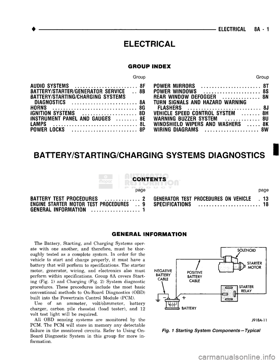
perform within specifications. Group 8A covers Start ing (Fig. 1) and Charging (Fig. 2) System diagnostic
procedures. These procedures include the most basic
conventional methods to On-Board Diagnostics (OBD)
built into the Powertrain Control Module (PCM).
Use of an ammeter, volt/ohmmeter, battery
charger, carbon pile rheostat (load tester), and 12
volt test light will be required.
All OBD sensing systems are monitored by the
PCM. The PCM will store in memory any detectable
failure in the monitored circuits. Refer to Using On-
Board Diagnostic System in this group for more in formation.
NEGATIVE
BATTERY
CABLE
A
7
POSITIVE
BATTERY
CABLE
BATTERY
J918A-11
Fig.
1 Starting
System
Components—Typical
Page 404 of 1502
AUDIO SYSTEMS
CONTENTS
SERVICE
PROCEDURES
page
.. 7
TEST PROCEDURES
page
.. 2
GENERAL
INFORMATION
For operation of the factory installed radios, refer
to the Owner Manual supplied with the vehicle. When connecting or disconnecting the Ignition Off
Draw (IOD) connector, it is important that the igni
tion switch be in the OFF position. Failure to place the ignition switch in the OFF po
sition can cause the radio display to become scram
bled when the IOD is disconnected. Connecting the IOD will correct the scrambled display.
INTERFERENCE
ELIMINATION
Many components are used on vehicles equipped
with a radio to suppress radio frequency interference (static). A capacitor is mounted inside the generator and
ground straps are utilized from cab to box and from
the engine to cowl. The previously mentioned Capacitor and Ground
Straps should be securely mounted to a clean ground
surface to work effectively. Radio resistance spark plug wires complete the in
terference suppression system. Faulty or deteriorated spark plug wires should be replaced.
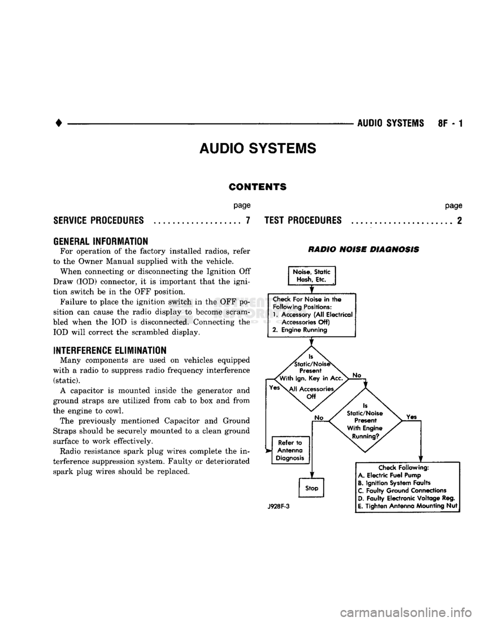
RADIO NOISE DIAGNOSIS
Noise,
Static
Hash,
Etc.
Check
For Noise in
the
Following
Positions:
1.
Accessory (All Electrical
Accessories
Off)
2. Engine Running
Is
'Static/NoiseS
Present
'With
Ign.
Key in Acc.
Yes\^|j
Accessories/
Off
No
Refer
to
Antenna
Diagnosis
f
Stop
No
Is
Static/Noise Present
With Engine
Running?.
Yes
J928F-3
Check
Following:
A.
Electric
Fuel
Pump
B.
Ignition
System
Faults
C.
Faulty Ground Connections
D.
Faulty Electronic Voltage Reg.
E.
Tighten Antenna Mounting Nut
Page 405 of 1502
![DODGE TRUCK 1993 Service Repair Manual
8F
- 2
AUDIO
SYSTEMS
• RADIO CONNECTOR PINS
BLACK
CHRYSLER
AM/FM STEREO
RADIOS
4 SPEAKERS
GRAY
BLACK
XL
GRAY
0@[3]S[3]@[D
X52 X54 VIEWED
FROM
X58
WIRE
END X56
E2 DODGE TRUCK 1993 Service Repair Manual
8F
- 2
AUDIO
SYSTEMS
• RADIO CONNECTOR PINS
BLACK
CHRYSLER
AM/FM STEREO
RADIOS
4 SPEAKERS
GRAY
BLACK
XL
GRAY
0@[3]S[3]@[D
X52 X54 VIEWED
FROM
X58
WIRE
END X56
E2](/manual-img/12/56922/w960_56922-404.png)
8F
- 2
AUDIO
SYSTEMS
• RADIO CONNECTOR PINS
BLACK
CHRYSLER
AM/FM STEREO
RADIOS
4 SPEAKERS
GRAY
BLACK
XL
GRAY
0@[3]S[3]@[D
X52 X54 VIEWED
FROM
X58
WIRE
END X56
E2 Ml
X51
X53 X57
X55
L7 XI2
AM/FM STEREO
RADIOS
2 SPEAKERS
BLACK
GRAY
4
BLACK
GRAY
[ZlSmEIULIlLT]
X54 X54 VIEWED
FROM
X56 WIRE END X56
E2
Ml
X53
X53 X55
X55
L7 X12
LEGEND:
E2-
ILLUMINATION
X51-LEFT
REAR FEED
X55-LEFT
DR RETURN L7-
PARK
LAMPS
X52-RIGHT
REAR FEED
X56-RIGHT
DR RETURN
Ml- BATTERY
X53-LEFT
DR FEED
X57-LEFT
REAR RETURN X12-ACC/RUN
X54-RIGHT
DR FEED
X58-RIGHT
REAR RETURN
J938F-8
TEST
PROCEDURES
RADIO DIAGNOSIS
Turn Ign. Key to
ACC.
T
Check
AM, FM and
Tape
Player
Operation
NOTE: FOR WIRE COLORS REFER TO
SECTION 8W-WIRING DIAGRAMS
Page 407 of 1502
8F - 4
AUDIO SYSTEMS
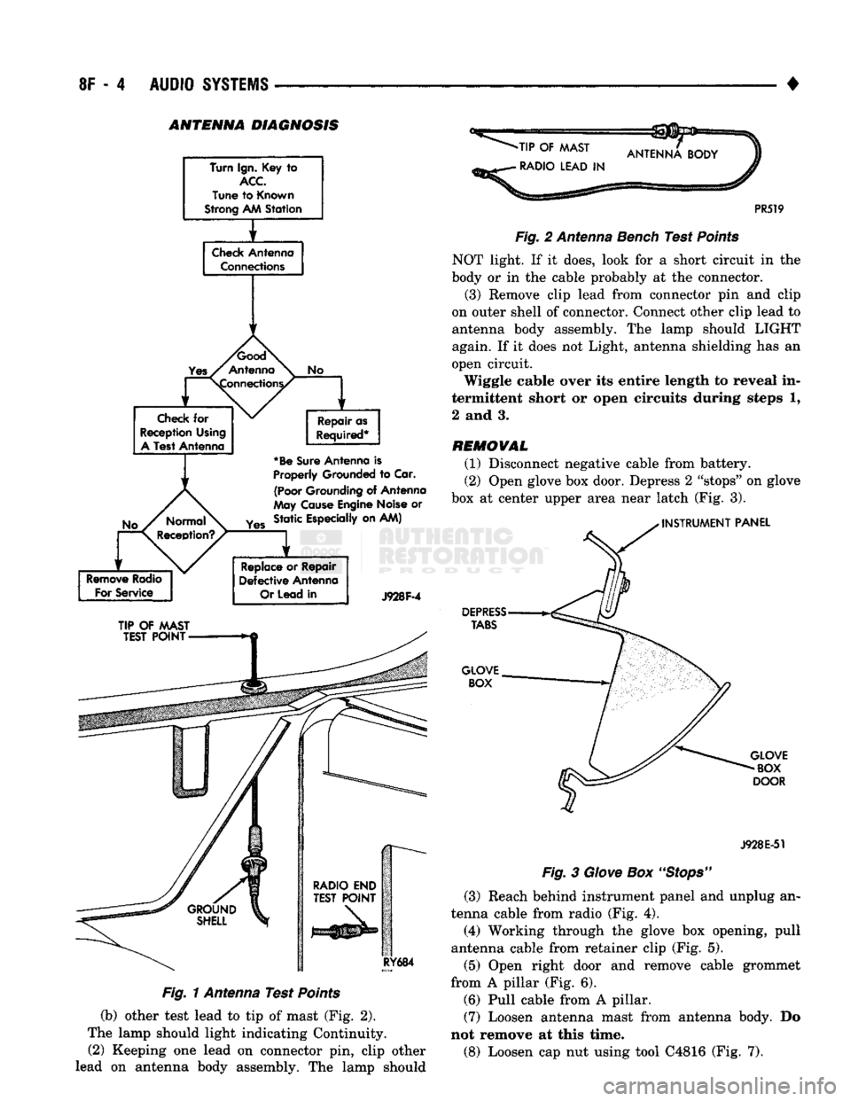
• ANTENNA DIAGNOSIS
Turn Ign. Key
to
ACC
Tune
to
Known
Strong AM
Station
f
Check
Antenna Connections
1
1
No
Check
for
Reception Using
A
Test Antenna Repair as
Required*
*Be
Sure
Antenna
is
Properly
Grounded
to
Car.
(Poor
Grounding
of
Antenna
May
Cause
Engine Noise
or
Yes
Static Especially on AM)
Remove
Radio
For
Service
Replace
or
Repair
Defective
Antenna
Or
Lead
in
J928F-4
TIP
OF
MAST
TEST
POINT
RY684
Fig. 1 Antenna Test Points
(b) other test lead to tip of mast (Fig. 2).
The lamp should light indicating Continuity. (2) Keeping one lead on connector pin, clip other
lead on antenna body assembly. The lamp should
-TIP
OF
MAST
•
RADIO LEAD
IN
PR519
Fig.
2 Antenna Bench Test
Points
NOT light. If it does, look for a short circuit in the
body or in the cable probably at the connector.
(3) Remove clip lead from connector pin and clip
on outer shell of connector. Connect other clip lead to
antenna body assembly. The lamp should LIGHT
again. If it does not Light, antenna shielding has an
open circuit.
Wiggle cable over its entire length to reveal in
termittent short or open circuits during steps 1,
2 and 3.
REMOVAL
(1) Disconnect negative cable from battery.
(2) Open glove box door. Depress 2 "stops" on glove
box at center upper area near latch (Fig. 3).
INSTRUMENT
PANEL
DEPRESS
TABS
GLOVE BOX
GLOVE
BOX
DOOR
J928E-51
Fig.
3
Glove
Box
"Stops"
(3) Reach behind instrument panel and unplug an
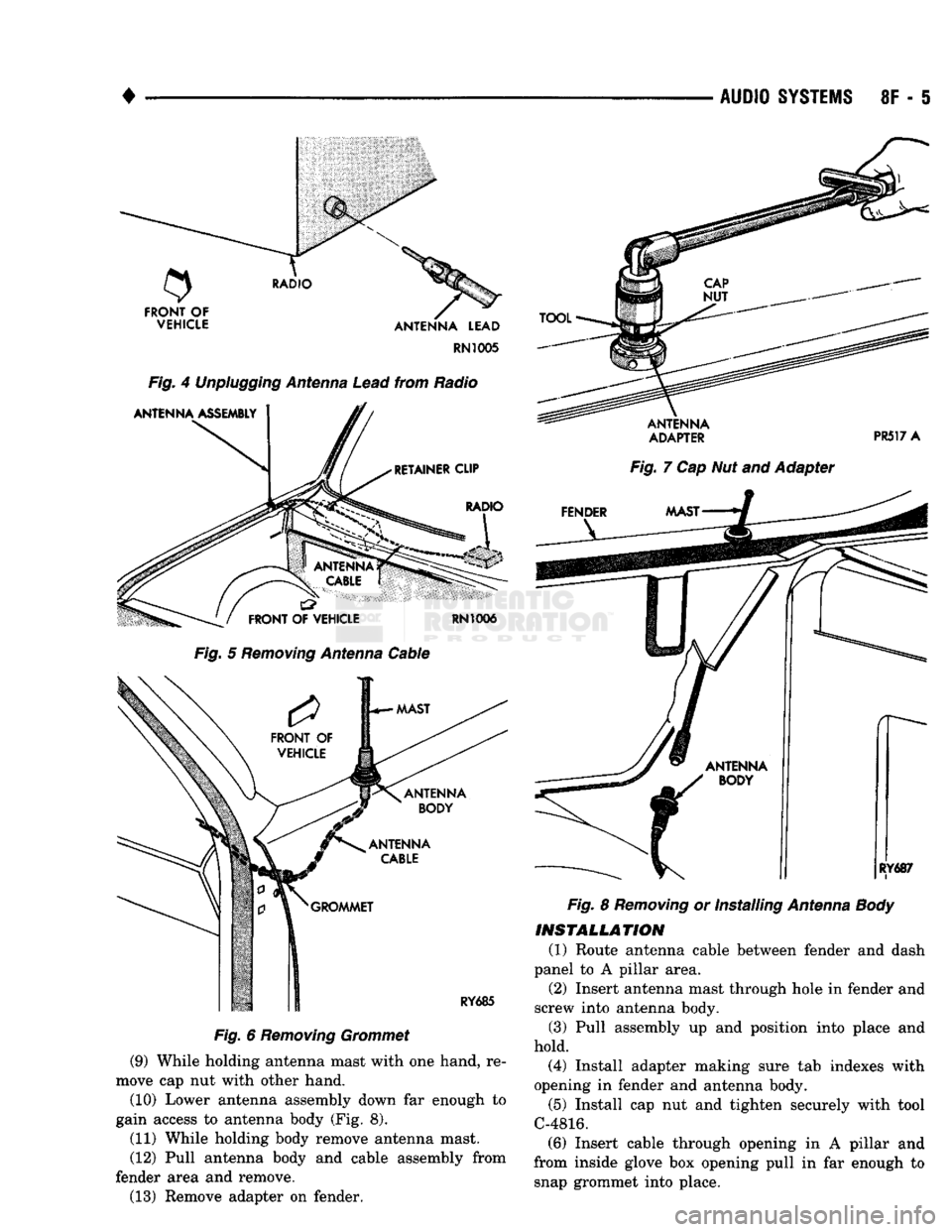
tenna cable from radio (Fig. 4).
(4) Working through the glove box opening, pull
antenna cable from retainer clip (Fig. 5).
(5) Open right door and remove cable grommet
from A pillar (Fig. 6). (6) Pull cable from A pillar. (7) Loosen antenna mast from antenna body. Do
not remove at this time.
(8) Loosen cap nut using tool C4816 (Fig. 7).
Page 408 of 1502
•
AUDIO
SYSTEMS
8F - 5
RN1005
Fig.
4
Unplugging
Antenna
Lead
from Radio
Fig.
5
Removing
Antenna
Cable
Fig.
6
Removing
Grommet
(9) While holding antenna mast with one hand, re
move cap nut with other hand.
(10) Lower antenna assembly down far enough to
gain access to antenna body (Fig. 8).
(11) While holding body remove antenna mast.
(12) Pull antenna body and cable assembly from
fender area and remove. (13) Remove adapter on fender.
ADAPTER
PR517 A
Fig.
7 Cap Nut and Adapter
Fig.
8
Removing
or Installing
Antenna
Body
INSTALLATION
(1) Route antenna cable between fender and dash
panel to A pillar area. (2) Insert antenna mast through hole in fender and
screw into antenna body.
(3) Pull assembly up and position into place and
hold. (4) Install adapter making sure tab indexes with
opening in fender and antenna body.
(5) Install cap nut and tighten securely with tool
C-4816. (6) Insert cable through opening in A pillar and
from inside glove box opening pull in far enough to snap grommet into place.
Page 409 of 1502
8F
- 6
AUDIO
SYSTEMS
•
(7) Route cable through retainer clip, over to radio,
and plug into back of radio. (8) Close glove box.
(9) Connect negative cable to battery.
CASSETTE
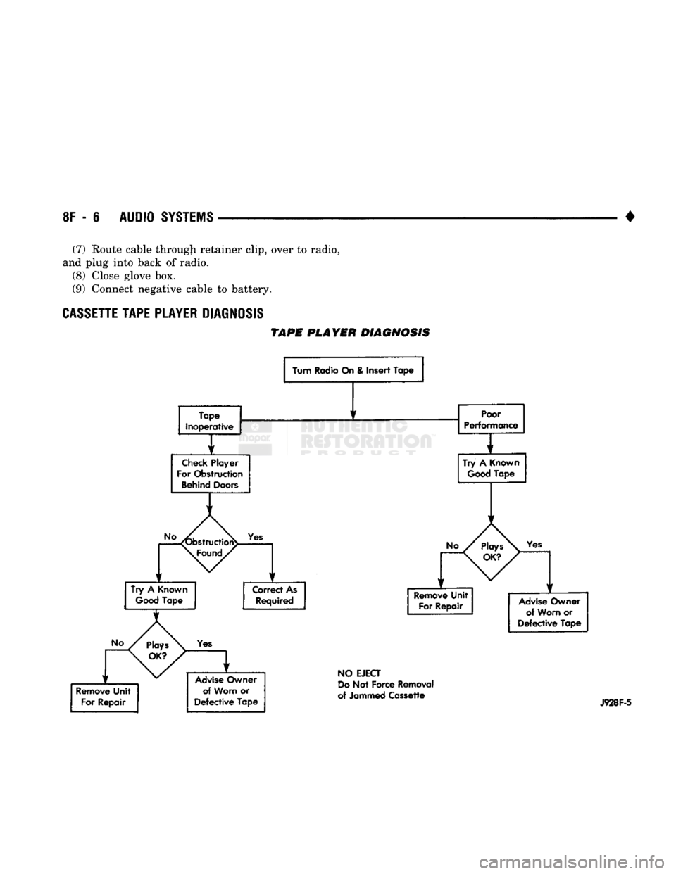
TAPE
PLAYER
DIAGNOSIS
TAPE
PLAYER DIAGNOSIS
Turn Radio On & Insert Tape
Tape
Inoperative
Check
Player
For Obstruction
Behind
Doors
Poor
Performance
1
Try
A
Good
Known
Tape
Yes
Try
A
Known
Good
Tape Correct As
Required
Yes
Advise
Owner of Worn
or
Defective
Tape
Yes
Remove
Unit For Repair
Advise
Owner
of Worn
or
Defective
Tape
NO
EJECT
Do
Not Force Removal
of Jammed Cassette
J928F-5
Page 410 of 1502
•
AUDIO
SYSTEMS
8F - 7
SERVICE
PROCEDURES
RADIO
REPLACEMENT
REMOVAL
(1) Disconnect negative cable from battery.
CAUTION:
Map
lamp
must
be
removed
to
prevent
damage
to instrument panel.
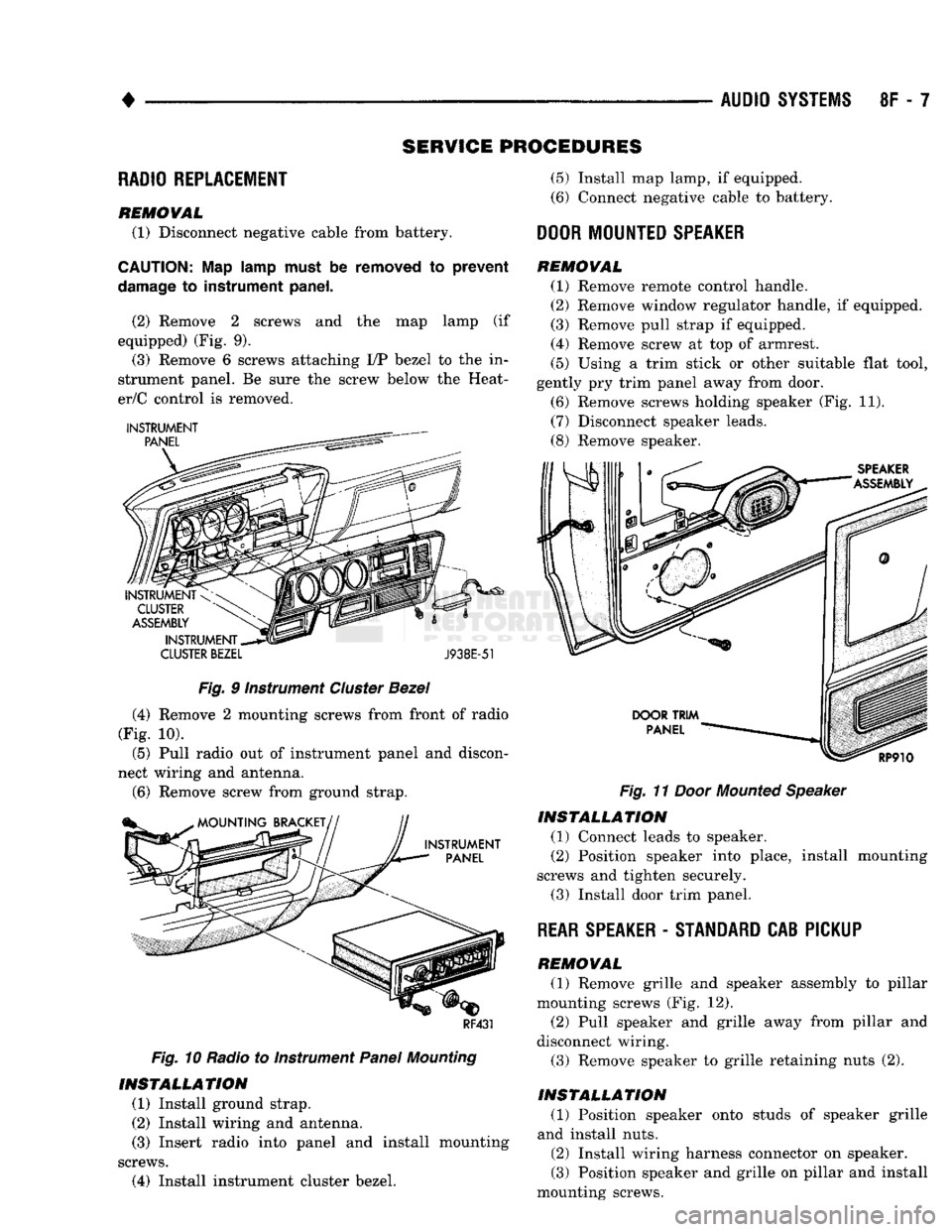
(2) Remove 2 screws and the map lamp (if
equipped) (Fig. 9). (3) Remove 6 screws attaching I/P bezel to the in
strument panel. Be sure the screw below the Heat-
er/C control is removed.
CLUSTER
BEZEL
J938E-51
Fig.
9 Instrument
Cluster
Bezel
(4) Remove 2 mounting screws from front of radio
(Fig. 10).
(5) Pull radio out of instrument panel and discon
nect wiring and antenna.
(6)
Remove screw from ground strap.
RF431
Fig.
10 Radio to Instrument
Panel
Mounting
INSTALLATION
(1) Install ground strap.
(2) Install wiring and antenna. (3) Insert radio into panel and install mounting
screws.
(4) Install instrument cluster bezel.
(5)
Install map lamp, if equipped.
(6) Connect negative cable to battery.
DOOR
MOUNTED
SPEAKER
REMOVAL
(1) Remove remote control handle.
(2) Remove window regulator handle, if equipped.
(3) Remove pull strap if equipped.
(4) Remove screw at top of armrest.
(5)
Using a trim stick or other suitable flat tool,
gently pry trim panel away from door.
(6) Remove screws holding speaker (Fig. 11).
(7) Disconnect speaker leads.
(8) Remove speaker.
Fig.
11
Door
Mounted
Speaker
INSTALLATION
(1) Connect leads to speaker.
(2) Position speaker into place, install mounting
screws and tighten securely.
(3) Install door trim panel.
REAR
SPEAKER
-
STANDARD
CAB PICKUP
REMOVAL
(1) Remove grille and speaker assembly to pillar
mounting screws (Fig. 12). (2) Pull speaker and grille away from pillar and
disconnect wiring.
(3) Remove speaker to grille retaining nuts (2).
INSTALLATION
(1) Position speaker onto studs of speaker grille
and install nuts.
(2) Install wiring harness connector on speaker.
(3) Position speaker and grille on pillar and install
mounting screws.
Page 1500 of 1502
COMPONENT AND SYSTEM INDEX
Name
Group-page
AUDIO
SYSTEMS
8F-1
SERVICE
PROCEDURES 8F-7
TEST PROCEDURES 8F-2
BATTERY/STARTER/GENERATOR SERVICE 8B-1 BATTERY SERVICE PROCEDURES 8B-1
GENERATOR SERVICE 8B-6
SPECIFICATIONS 8B-9
STARTER SERVICE PROCEDURES 8B-4
BODY COMPONENTS 23-1 CAB/BODY INTERIOR COMPONENTS
23-35
DOORS
23-21
EXTERIOR COMPONENTS 23-1
FIXED GLASS
23-29
PAINT
CODE CHART
23-54
REFINISHING PROCEDURES
23-54
BRAKES
5-1 BENDIX DISC BRAKE 5-37 BRAKE ADJUSTMENTS-BRAKE BLEEDING 5-7
BRAKE DIAGNOSIS 5-3
CHRYSLER
DISC BRAKE 5-27 DRUM BRAKES—ELEVEN INCH 5-46
DRUM BRAKES-TWELVE INCH 5-50
GENERAL INFORMATION 5-1 MASTER CYLINDER—COMBINATION VALVE-BRAKE
LINES 5-10
PARKING BRAKES 5-56
POWER BRAKE BOOSTER-BRAKE PEDAL 5-20 POWER BRAKE VACUUM PUMP-DIESEL ENGINE. . 5-22
REAR
WHEEL ANTILOCK
(RWAL)
BRAKES 5-59
SPECIFICATIONS 5-65
CHIME/BUZZER WARNING
SYSTEMS
8U-1
CLUTCH 6-1 CLUTCH DIAGNOSIS 6-2 CLUTCH SERVICE 6-11
COOLING SYSTEM 7-1
DIAGNOSIS 7-4
ENGINE ACCESSORY DRIVE BELTS 7-40
ENGINE BLOCK HEATERS 7-48
SERVICE
PROCEDURES 7-15 SPECIFICATIONS 7-49
ELECTRICAL 8A-1 BATTERY TEST PROCEDURES 8A-2
ENGINE STARTER MOTOR TEST PROCEDURES.... 8A-9
GENERAL INFORMATION 8A-1
GENERATOR TEST PROCEDURES ON VEHICLE . . . 8A-13
GROUP INDEX 8A-1
SPECIFICATIONS 8A-18
BATTERY/STARTING/CHARGING
SYSTEMS
DIAGNOSTICS 8A-1
EMISSION
CONTROL
SYSTEMS.
25-1 AIR INJECTION SYSTEM—5.9L HDC-GAS ENGINE . 25-15 COMPONENT REMOVAL/INSTALLATION 25-17 EVAPORATIVE EMISSION CONTROLS 25-6
EXHAUST EMISSION CONTROLS 25-10
GENERAL INFORMATION 25-1
ENGINES 9-1 3.9L ENGINE SERVICE PROCEDURES 9-17 5.2L ENGINE SERVICE PROCEDURES 9-47
5.9L (DIESEL) ENGINE SERVICE PROCEDURES . . . 9-107
Name
Group-page
5.9L ENGINE SERVICE PROCEDURES 9-77 ENGINE DIAGNOSIS 9-5
STANDARD SERVICE PROCEDURES 9-1
EXHAUST SYSTEM AND INTAKE MANIFOLD 11-1
EXHAUST SYSTEM DIAGNOSIS 11-3
GENERAL INFORMATION 11-1
SERVICE
PROCEDURES (DIESEL ENGINES) 11-17
SERVICE
PROCEDURES (GASOLINE ENGINES) 11-4
SPECIFICATIONS 11-27
FRAME AND BUMPERS 13-1 ATTACHED COMPONENTS 13-30
BUMPERS
13-1
FRAME 13-20
SNOW PLOW 13-3
FRONT SUSPENSION AND AXLE 2-1 FRONT SUSPENSION—2WD VEHICLES 2-7
FRONT SUSPENSION—4WD VEHICLES 2-14 FRONT WHEEL ALIGNMENT 2-3
GENERAL INFORMATION 2-1 MODEL 44 FRONT AXLE 2-17
MODEL 60 FRONT AXLE 2-49
TORQUE SPECIFICATIONS 2-75
FUEL SYSTEM 14-1 ACCELERATOR PEDAL AND THROTTLE CABLE . . . 14-25
DIESEL
FUEL INJECTION—COMPONENT DESCRIPTION/SYSTEM OPERATION 14-76
DIESEL
FUEL INJECTION-GENERAL DIAGNOSIS. . 14-88
DIESEL
FUEL INJECTION-SERVICE
PROCEDURES
14-106
FUEL DELIVERY SYSTEM-EXCEPT DIESEL 14-3
FUEL DELIVERY-DIESEL ENGINE 14-15 FUEL TANKS 14-20
GENERAL INFORMATION 14-1 MULTI-PORT FUEL INJECTION (MPI)-COMPONENT DESCRIPTION/SYSTEM OPERATION-EXCEPT
DIESEL
14-29
MULTI-PORT FUEL INJECTION
(MPlj-COMPONENT
REMOVAL/INSTALLATION-EXCEPT DIESEL .... 14-64
MULTI-PORT FUEL INJECTION (MPI)—GENERAL DIAGNOSIS-EXCEPT DIESEL 14-43
SERVICE
ADJUSTMENTS-DIESEL
14-122
SPECIFICATIONS
14-123
HEATING AND AIR CONDITIONING 24-1 CLIMATE CONTROL SYSTEM
24-29
COMPRESSOR
SERVICE
(SD-709)
24-21 DIAGNOSTIC PROCEDURES 24-3
GENERAL INFORMATION 24-1 REFRIGERANT SYSTEM SERVICE PROCEDURES . . 24-17
TORQUE SPECIFICATIONS
24-39
HORNS 8G-1
SERVICE
PROCEDURES 8G-3
TEST PROCEDURES 8G-1
IGNITION
SYSTEMS
8D-1 COMPONENT IDENTIFICATION/SYSTEM OPERATION. 8D-1
COMPONENT REMOVAL/INSTALLATION 8D-18 DIAGNOSTICS/SERVICE PROCEDURES 8D-7
IGNITION
SWITCH
8D-25
SPECIFICATIONS
8D-28
INSTRUMENT PANEL AND GAUGES 8E-1