1993 DODGE TRUCK turn signal bulb
[x] Cancel search: turn signal bulbPage 396 of 1502
•
INSTRUMENT PANEL
AND
GAUGES
8E - 15
PRND21 INDICATOR
REMOVAL
(1) Remove bezel. Refer to Cluster Bezel Removal.
(2)
Remove cluster mask and lens. Refer to Cluster
Mask and Lens Removal. (3) Remove cluster assembly. Refer to Instrument
Cluster Removal. (4) Remove screws attaching PRND21 mechanism
to cluster housing.
(5)
Remove PRND21 mechanism.
INSTALLATION (1) Position PRND21 mechanism to cluster hous
ing. (2) Install mounting screws.
(3)
Install cluster assembly. (4) Install mask-lens.
(5)
Install bezel.
LAMP BULBS
CLUSTER ILLUMINATION LAMPS TURN SIGNAL INDICATOR LAMPS
LOW OIL PRESSURE INDICATOR LAMP
HIGH BEAM INDICATOR LAMP CHECK ENGINE LAMP
SEAT BELT WARNING LAMP
REMOVAL (1) Disconnect negative cable from battery.
(2) Remove instrument cluster. See cluster re
moval.
(3)
Twist lamp socket assembly and remove from
printed circuit board. (4) Remove bulb from socket.
INSTALLATION (1) Install bulb into socket.
(2) Install socket assembly into printed circuit
board.
(3)
Position cluster into place in panel. See cluster
installation. (4) Connect battery negative cable.
LAMP BULB REPLACEMENT—MESSAGE CENTER
REMOVAL (1) Disconnect battery negative cable.
(2) Remove instrument cluster bezel assembly. Re
fer to Instrument Cluster removal.
(3)
Twist lamp socket assembly and remove from
printed circuit board. (4) Remove bulb from socket.
INSTALLATION (1) Install bulb into socket assembly. (2) Install lamp socket assembly into printed cir
cuit board.
(3)
Install Instrument Cluster bezel assembly to
instrument panel. Refer to Instrument Cluster instal
lation.
(4) Connect negative cable from battery.
FOUR WHEEL DRIVE INDICATOR LAMP (1) Pull bulb and socket assembly from rear of
housing. (2) Remove bulb from socket.
(3)
Reverse removal procedures to install.
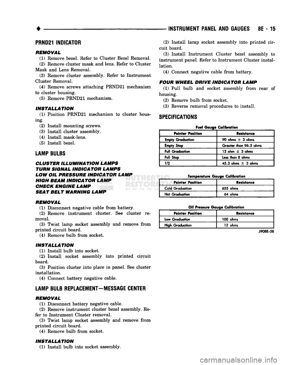
SPECIFICATIONS
Fuel
Gauge Calibration
Mntar Position Resistance
Empty Graduation 90
ohms
± 3
ohms
Empty Stop
Greater
than
96.5 ohms
Full
Graduation 12 ohm
± 3
ohms
Full
Stop
Less
than
8
ohms
1/2
45.3 ohms
± 3
ohms
Temperature
Gauge
Calibration
Pointer
Position Resistance
Cold Graduation 655 ohms
Hot Graduation 64 ohms
Oil Pressure Gauge Calibration
Pointer
Position Resistance
Low Graduation 100 ohms
High Graduation 12 ohms
J908E-58
Page 428 of 1502
•
TURN SIGNALS
AND
HAZARD WARNING FLASHER
8J - 1
CONTENTS
page page
GENERAL
INFORMATION
1
MULTIFUNCTION SWITCH TESTING MULTIFUNCTION SWITCH SERVICE PROCEDURES
2
PROCEDURES
3
GENERAL
INFORMATION
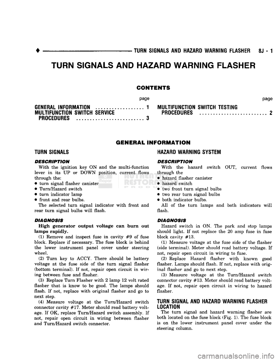
TURN SIGNALS
DESCRIPTION With
the
ignition
key ON and the
multi-function
lever
in its UP or
DOWN position, current flows
through
the:
• turn signal flasher canister • Turn/Hazard switch
• turn indicator lamp
• front
and
rear bulbs. The selected turn signal indicator with front
and
rear turn signal bulbs will flash.
DIAGNOSIS High generator output voltage
can
burn
out
lamps rapidly. (1) Remove
and
inspect fuse
in
cavity
#9 of
fuse
block. Replace
if
necessary.
The
fuse block
is
behind
the lower instrument panel cover under steering wheel. (2) Turn
key to
ACCY. There should
be
battery
voltage
at the
fuse side
of the
turn signal flasher (bottom terminal).
If
not,
repair open circuit
in
wir
ing between fuse
and
flasher.
(3) Replace Turn Flasher with
2
lamp
12
volt rated
flasher that
is
know
to be
good.
The
lamps should
flash. If
not,
replace with original flasher
and
go to
next step.
(4) Measure voltage
at the
Turn/Hazard switch
connector cavity
#17.
Meter should read battery volt
age.
If
OK,
replace Turn/Hazard switch assembly.
If
not, repair open circuit
in
wiring between flasher
and Turn/Hazard switch connector.
HAZARD WARNING SYSTEM
DESCRIPTION
With
the
hazard switch
OUT,
current flows
through
the
• hazard flasher canister
• hazard switch
•
two
front turn signal bulbs
•
two
rear turn signal bulbs
• both indicator bulbs.
All
of the
turn lamps
and
both indicators will
flash.
DIAGNOSIS Hazard switch
in
ON.
The
park
and
stop lamps
should light.
If
not
replace
the 20
amp
fuse
in
fuse
block cavity
#13.
(1) Measure voltage
at
the
fuse side
of
the
flasher
(side terminal). Meter should read battery voltage.
If
not, repair open circuit
in
wiring
to
fuse. (2) Replace Hazard flasher with known good
flasher. Lamps should flash.
If
not, replace with orig
inal flasher
and go
to
next step.
(3) Measure voltage
at the
Turn/Hazard switch
connector cavity #13. Meter should read battery volt
age.
If
not,
repair open circuit
in
wiring
to
hazard
flasher.
TURN
SIGNAL AND HAZARD
WARNING
FLASHER
LOCATION
The turn signal
and
hazard warning flasher
are
both located
on the
fuse block (Fig.
1). The
fuse block is
on the
lower instrument panel cover under
the
steering column.
TURN SIGNALS AND HAZARD WARNING
FLASHER
Page 444 of 1502
•
LAMPS
LAMPS
8L - 1
CONTENTS
page page
BULB
APPLICATION 11 EXTERIOR
LAMPS
SERVICE
PROCEDURES
... 3
EXTERIOR
LAMPS
1 INTERIOR
LAMPS
10
EXTERIOR LAMPS
GENERAL
INFORMATION Each vehicle is equipped with various lamp assem
blies.
A good ground is necessary for proper lighting operation. When changing lamp bulbs check the socket for
corrosion. Clean corrosion with a wire brush. Coat
the inside of the socket lightly with Mopar® Multi- Purpose Grease or equivalent.
DIAGNOSTIC
PROCEDURES
Always begin any diagnosis by testing all of the
fuses and circuit breakers in the system. Refer to Group 8W, Wiring Diagrams. Conventional and halogen headlamps are inter
changeable. It is recommended that they not be in
termixed on a given vehicle.
MULTI-FUNCTION
SWITCH TESTING
PROCEDURES
The multi-function switch contains electrical cir
cuitry for:
• Headlamp Dimmer Switch
• Passing Lights
• Turn Signals
• Hazard Warning • Windshield Wiper
• Pulse Wiper
• Windshield Washer
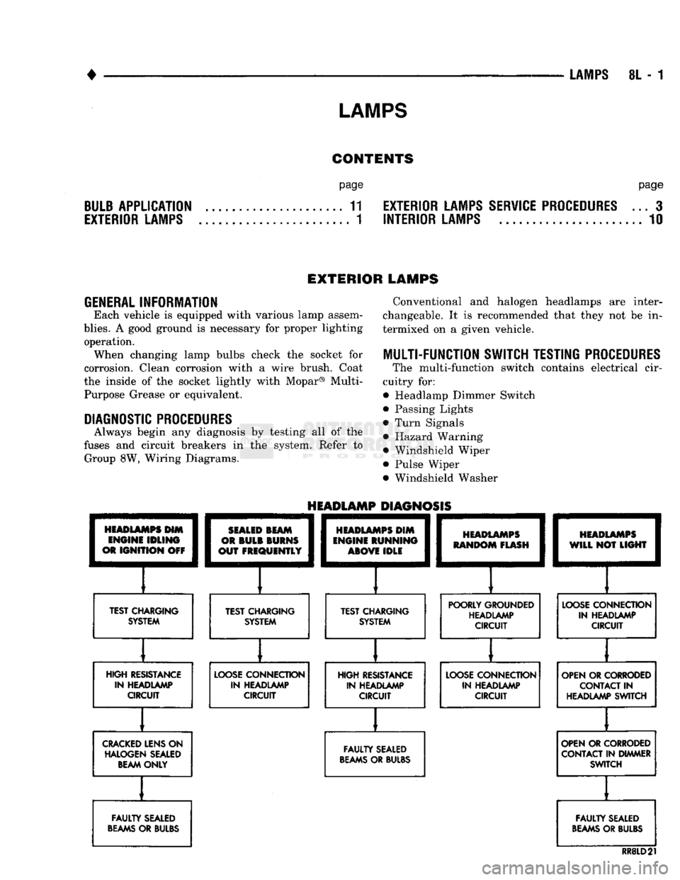
HEADLAMPS
HIM
ENGINE
IDLING
OR
IGNITION
OFF
TEST CHARGING
SYSTEM
HEADLAMP
DIAGNOSIS
SEALED
BEAM
OR
BULB
BURNS
OUT
FREQUENTLY
][
TEST CHARGING SYSTEM
HEADLAMPS
DIM
ENGINE
RUNNING
ABOVE
IDLE
][
TEST CHARGING SYSTEM
HEADLAMPS
RANDOM
FLASH
[
HEADLAMPS
WILL
NOT
LIGHT
POORLY GROUNDED HEADLAMP CIRCUIT
LOOSE
CONNECTION
IN HEADLAMP CIRCUIT
HIGH RESISTANCE IN HEADLAMP CIRCUIT
LOOSE
CONNECTION
IN HEADLAMP CIRCUIT HIGH RESISTANCE
IN HEADLAMP CIRCUIT
LOOSE
CONNECTION
IN HEADLAMP CIRCUIT OPEN OR CORRODED
CONTACT
IN
HEADLAMP SWITCH
CRACKED
LENS ON HALOGEN SEALED BEAM ONLY
FAULTY
SEALED
BEAMS
OR BULBS OPEN OR CORRODED
CONTACT IN DIMMER SWITCH
FAULTY
SEALED
BEAMS
OR BULBS
FAULTY
SEALED
BEAMS
OR BULBS
RR8LD21
Page 446 of 1502

•
LAMPS
8L - 3
EXTERIOR
LAMPS
SERWICE PROCEDURES
INDEX
page
Cargo
Lamp
7
Clearance Lamps
for
Dual Wheel Model
........
5
Daytime Running
Light
Module (Canada Only)
... 8
Front
Park
and
Turn Signal Lamp Bulb
4
Headlamp
Adjustment
Using
Alignment
Screen
... 3
Headlamp
Alignment
3
Headlamp
Alignment
Preparation
3
page
Headlamp Switch
4
License
Lamp
............................
7
Sealed
Beam Replacement
4
Side
Marker Lamp
and
Bulb
. 5
Tail,
Stop, Turn Signal, Rear Side Marker
and
Back-Up
Lamps
5
Underhood Lamp
8
HEADLAMP
ALIGNMENT
Headlamps
can be
aligned using
the
screen method
provided
in
this section. Alignment Tool C4466-A
or
equivalent
can
also
be
used. Refer
to
instructions
provided with
the
tool
for
proper procedures.
The
preferred headlamp alignment setting
is 0 for
the left/right adjustment
and
1" down
for the up/
down adjustment.
HEADLAMP
ALIGNMENT PREPARATION
(1) Verify headlamp dimmer switch
and
high beam
indicator operation. (2) Correct defective components that could hinder
proper headlamp alignment. (3) Verify proper tire inflation. (4) Clean headlamp lenses.
(5) Verify that luggage area
is not
heavily loaded.
(6) Fuel tank should
be
FULL.
Add 2.94 kg (6.5
lbs.)
of
weight over
the
fuel tank
for
each estimated
gallon
of
missing fuel.
HEADLAMP
ADJUSTMENT USING ALIGNMENT
SCREEN
ALIGNMENT SCREEN PREPARATION (1) Position vehicle
on a
level surface perpendicu
lar
to a
flat wall
7.62
meters
(25 ft)
away from front
of headlamp lens.
(2)
If
necessary, tape
a
line
on the
floor
7.62
meters
(25 ft)
away from
and
parallel
to the
wall.
CENTER
OF
VEHICLE
TO
CENTER
OF
HEADLAMP
LENS
VEHICLE
CENTERLINE" LOW BEAM
HOT
SPOT AREA FLOOR
TO
CENTER
OF
HEADLAMP
LENS
PREFERRED
HOT SPOT
LOCATION
7.62
METERS
(25
FEET)
FRONT
OF
HEADLAMP
938L-25X
Fig.
1 Headlamp
Alignment
Screen
—Typical
Page 447 of 1502
8L
- 4
LAMPS
• (3) Up 1.27 meters (5 feet) from the floor, tape a
line on the wall at the centerline of the vehicle.
Sight along the centerline of the vehicle (from rear of
vehicle forward) to verify accuracy of the line place
ment.
(4) Rock vehicle side-to-side three times to allow
suspension to stabilize. (5) Jounce front suspension three times by pushing
downward on front bumper and releasing. (6) Measure the distance from the center of head
lamp lens to the floor. Transfer measurement to the alignment screen (with tape). Use this line for up/
down adjustment reference.
(7) Measure distance from the centerline of the ve
hicle to the center of each headlamp being aligned. Transfer measurements to screen (with tape) to each side of vehicle centerline. Use these lines for left/
right adjustment reference.
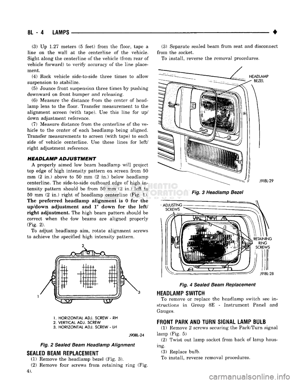
HEADLAMP
ADJUSTMENT
A properly aimed low beam headlamp will project
top edge of high intensity pattern on screen from 50 mm (2 in.) above to 50 mm (2 in.) below headlamp
centerline. The side-to-side outboard edge of high in
tensity pattern should be from 50 mm (2 in.) left to 50 mm (2 in.) right of headlamp centerline (Fig. 1).
The preferred headlamp alignment is 0 for the
up/down adjustment and 1" down for the left/
right adjustment. The high beam pattern should be correct when the iow beams are aligned properly (Fig. 2).
To adjust headlamp aim, rotate alignment screws
to achieve the specified high intensity pattern.
1.
HORIZONTAL
ADJ. SCREW
- RH
2.
VERTICAL
ADJ. SCREW
3.
HORIZONTAL
ADJ. SCREW
- LH
J908L-24
Fig.
2
Sealed
Beam
Headlamp
Alignment
SEALED
BEAM REPLACEMENT
(1) Remove the headlamp bezel (Fig. 3).
(2) Remove four screws from retaining ring (Fig.
4).
(3) Separate sealed beam from seat and disconnect
from the socket. To install, reverse the removal procedures.
HEADLAMP
BEZEL
: ') J918L-29
Fig.
3 Headlamp
Bezel
RETAINING
RING
SCREWS
J918L-28
Fig.
4
Sealed
Beam
Replacement
HEADLAMP SWITCH
To remove or replace the headlamp switch see in
structions in Group 8E - Instrument Panel and
Gauges.
FRONT
PARK AND
TURN
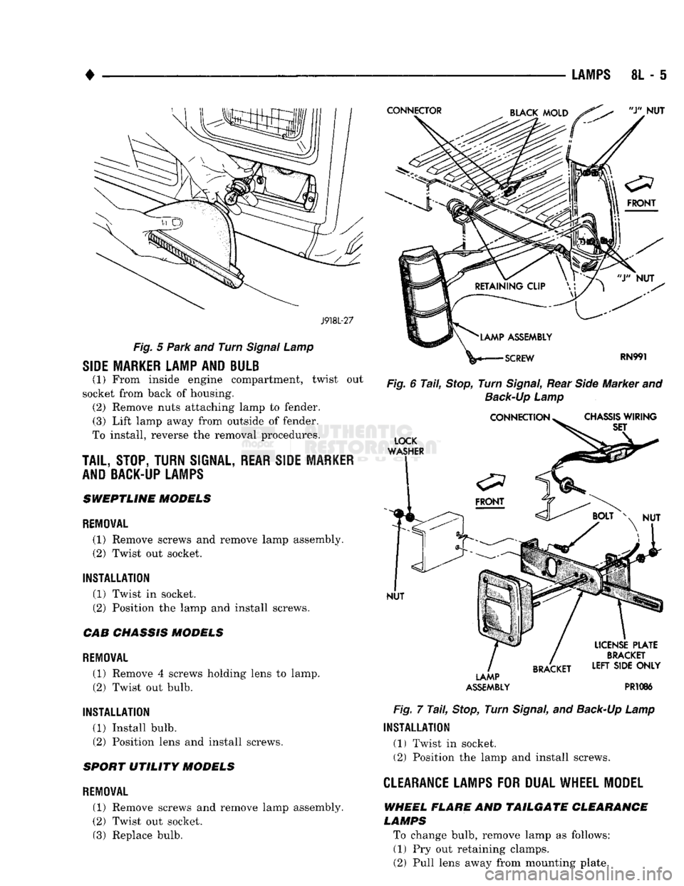
SIGNAL LAMP BULB
(1) Remove 2 screws securing the Park/Turn signal
lamp (Fig. 5) (2) Twist out lamp socket from back of lamp hous
ing. (3) Replace bulb.
To install, reverse removal procedures.
Page 448 of 1502
•
LAMPS
8L - 5
J918L-27
Fig.
5
Park
and Turn
Signal
Lamp
SIDE MARKER LAMP AND BULB
(1) From inside engine compartment, twist out
socket from back of housing. (2) Remove nuts attaching lamp to fender. (3) Lift lamp away from outside of fender.
To install, reverse the removal procedures.
TAIL,
STOP, TURN
SIGNAL,
REAR SIDE MARKER
AND BACK-UP LAMPS
SWEPTLINE MODELS
REMOVAL
(1) Remove screws and remove lamp assembly.
(2) Twist out socket.
INSTALLATION (1) Twist in socket.
(2) Position the lamp and install screws.
CAB CHASSIS MODELS
REMOVAL (1) Remove 4 screws holding lens to lamp. (2) Twist out bulb.
INSTALLATION (1) Install bulb.
(2) Position lens and install screws.
SPORT UTILITY MODELS
REMOVAL
(1) Remove screws and remove lamp assembly.
(2) Twist out socket. (3) Replace bulb.
Fig.
6
Tail,
Stop,
Turn
Signal,
Rear
Side
Marker and
Back-Up
Lamp
LAMP
ASSEMBLY
PR1086
Fig.
7
Tail,
Stop,
Turn
Signal,
and
Back-Up
Lamp
INSTALLATION
(1) Twist in socket. (2) Position the lamp and install screws.
CLEARANCE LAMPS
FOR
DUAL WHEEL MODEL
WHEEL FLARE AND TAILGATE CLEARANCE
LAMPS
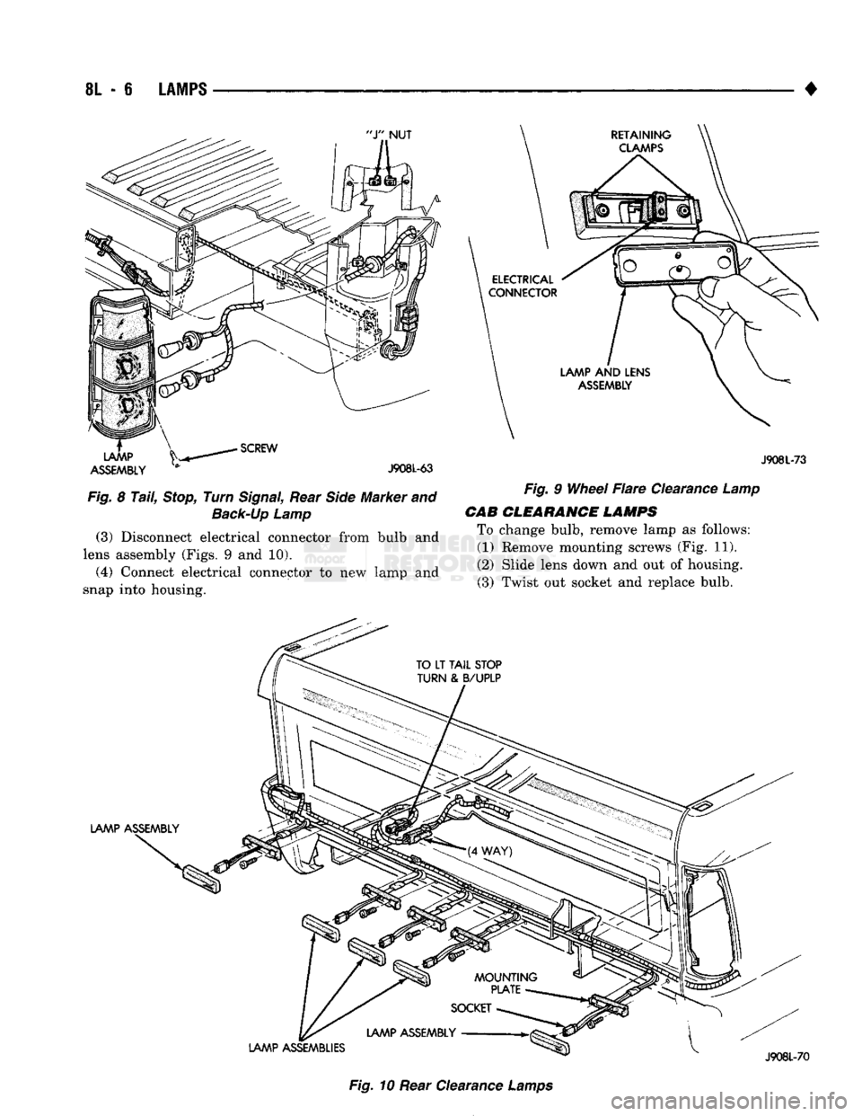
To change bulb, remove lamp as follows: (1) Pry out retaining clamps.
(2) Pull lens away from mounting plate.
Page 449 of 1502
8L
- 6
LAMPS
•
ASSEMBLY
* J908L-63
Fig.
8
Tail,
Stop,
Turn
Signal,
Rear
Side
Marker and
Back-Up
Lamp
(3)
Disconnect electrical connector from bulb and
lens assembly (Figs. 9 and 10).
(4) Connect electrical connector to new lamp and
snap into housing. J908L-73
Fig.
9
Wheel
Flare
Clearance
Lamp
CAB
CLEARANCE LAMPS
To change bulb, remove lamp as follows: (1) Remove mounting screws (Fig. 11).
(2) Slide lens down and out of housing. (3) Twist out socket and replace bulb.
Fig.
10 Rear Clearance
Lamps
Page 451 of 1502
8L
- 8
LAMPS
CONNECTOR
CUP
FRONT
LAMP
ASSEMBLY
LICENSE
PLATE
SCREW
LAMP
ASSEMBLY
LICENSE
PLATE
RR8LD24
Fig.
15
License
Plate
Lamps
-
Step
Bumper
TO
TAIL,
STOP,
TURN
SIG. AND
BACK
UP
LAMPS
LICENSE
PLATE
LICENSE
PLATE
LAMP
AND
LAMP
CONNECTOR
BRACKET
ASSEMBLY
J908L-74
Fig.
16
License
Plate
Lamp
Without Rear
Bumper
UNDERHOOD
LAMP
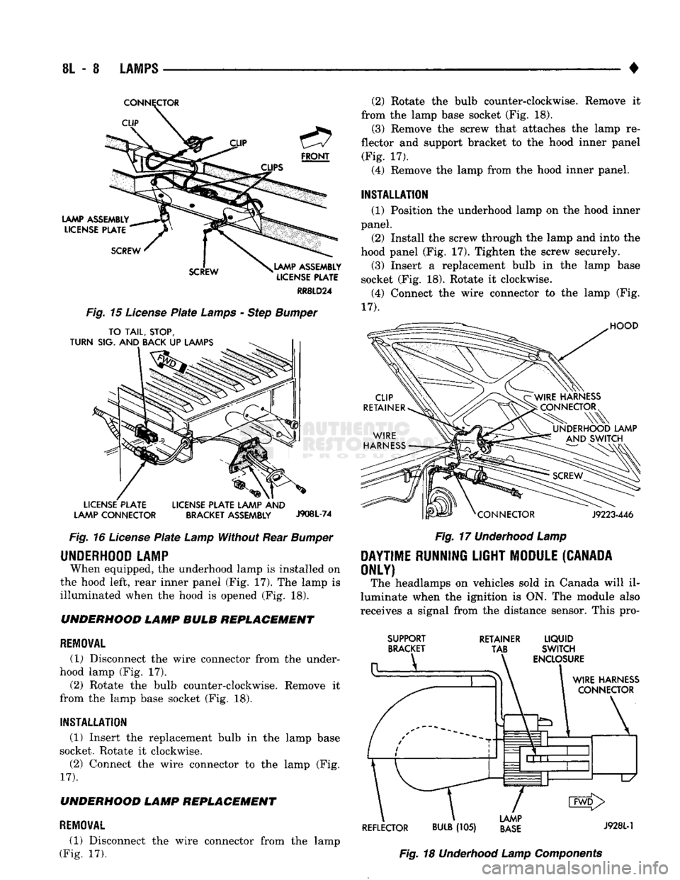
When equipped, the underhood lamp is installed on
the hood left, rear inner panel (Fig, 17). The lamp is
illuminated when the hood is opened (Fig. 18). UNDERHOOD LAMP BULB REPLACEMENT
REMOVAL
(1) Disconnect the wire connector from the under
hood lamp (Fig. 17).
(2) Rotate the bulb counter-clockwise. Remove it
from the lamp base socket (Fig. 18).
INSTALLATION
(1) Insert the replacement bulb in the lamp base
socket. Rotate it clockwise.
(2) Connect the wire connector to the lamp (Fig.
17).
UNDERHOOD LAMP REPLACEMENT
REMOVAL
(1) Disconnect the wire connector from the lamp
(Fig. 17). (2) Rotate the bulb counter-clockwise. Remove it
from the lamp base socket (Fig. 18). (3) Remove the screw that attaches the lamp re
flector and support bracket to the hood inner panel (Fig. 17).
(4) Remove the lamp from the hood inner panel.
INSTALLATION (1) Position the underhood lamp on the hood inner
panel. (2) Install the screw through the lamp and into the
hood panel (Fig. 17). Tighten the screw securely. (3) Insert a replacement bulb in the lamp base
socket (Fig. 18). Rotate it clockwise. (4) Connect the wire connector to the lamp (Fig.
17).
HOOD
J9223-446
Fig.
17
Underhood
Lamp
DAYTIME
RUNNING
LIGHT
MODULE
(CANADA
ONLY)
The headlamps on vehicles sold in Canada will il
luminate when the ignition is ON. The module also
receives a signal from the distance sensor. This pro-
SUPPORT
BRACKET RETAINER
LIQUID
TAB SWITCH
ENCLOSURE
WIRE
HARNESS
CONNECTOR
\
1
d1^—1—l
L/
CMD>
LAMP
REFLECTOR
BULB
(105)
BASE
J9281"1
Fig.
18
Underhood
Lamp
Components