1993 DODGE TRUCK width
[x] Cancel search: widthPage 9 of 1502
4 INTRODUCTION
• VEHICLE DIMENSIONS
VEHICLE
FAMILY
WHEELBASE
AVAILABLE
CAB
TO
AXLE BODY
TYPE
SfANDAID
SODIES
AVAILABLE
VEHICLE
FAMILY
WHEELBASE
AVAILABLE
CAB
TO
AXLE BODY
TYPE
NOMINAL
LENGTH
(LOAD
SPACE
D
MENSIONS
(2)
VEHICLE
FAMILY
WHEELBASE
AVAILABLE
CAB
TO
AXLE BODY
TYPE
NOMINAL
LENGTH LENGTH MAX.
WIDTH
HEIGHT
VOLUME
AD-1
AD-5
2921
mm
(115
in) —
Sweptline
1981
mm
(6.5
ft)
1981
mm
(78
in)
1778 mm
(70
in)
485 mm
19.1
in) 1.71 m3
(60.35
ft3)
AD-1
AD-2
AD-3
AD-5
AD-6
AD-7
3327
mm
(131
in) —
Sweptline
2438 mm
(8
ft)
2489 mm
(98
in)
1778 mm
(70
in)
485 mm
(19.1
in)
2.15
m3
(75.8
ft3)
AD-2
AD-3
AD-7
3327
mm
(131
in)
1422 mm
(56
in)
Chassis
Cab
2438 mm
(8
ft)
—
— — —
AD-3
AD-7
3249 mm
(135
in)
1524 mm
(60
in)
Chassis
Cab
2896 mm
(9.5
ft) —
— — —
AD-3
4039 mm
(159
in)
2134 mm
(84
in)
Chassis
Cab
3810 mm
(12.5
ft)
—
— —
AD-4
2692
mm
(106
in)
Sport
Utility
4x2
—
1778 mm 1588 mm
(62.5
in)
1062 mm
(41.8
in)
2.99
m3
(105.8
ft3)
AD-8
2692
mm
(106
in)
Sport
Utility
4x4
—
1778 mm 1588 mm
(62.5
in)
1062 mm
(41.8
in)
2.99
m3
(105.8
ft3)
AD-1
3378 mm
(133
in) —
Sweptline
1981
mm
(6.5
ft)
1984 mm
(78.1
in)
1778 mm
(70
in)
485 mm
(19.1
in) 1.71 m3
(60.4
ft3)
AD-1
AD-2
AD-5
AD-6
3785 mm
(149
in) —
Sweptline
Club
Cab 2438 mm
(8
ft)
2489 mm
(98
in)
1778 mm
(70
in)
485 mm
(19.1
in)
2.15
M3
(75.8
ft3)
®
Driver seat
to
tailgate.
(2)
Based
on
S.A.E.
procedure
Jl
100. J901N-34
VEHICLE
WEIGHTS
The Vehicle Weights chart provides:
• The Gross Vehicle Weight Rating (GVWR),
• The payload
• The curb weight
for
each vehicle type/wheelbase
TRAILER
TOWING
SPECIFICATIONS
The Trailer Towing Specifications chart provides:
• The maximum trailer tongue weight
• The maximum trailer weight
• The maximum combined weight of the trailer/load/
towing vehicle with
a
specific engine/transmission/ axle combination.
VEHICLE
DIMENSION
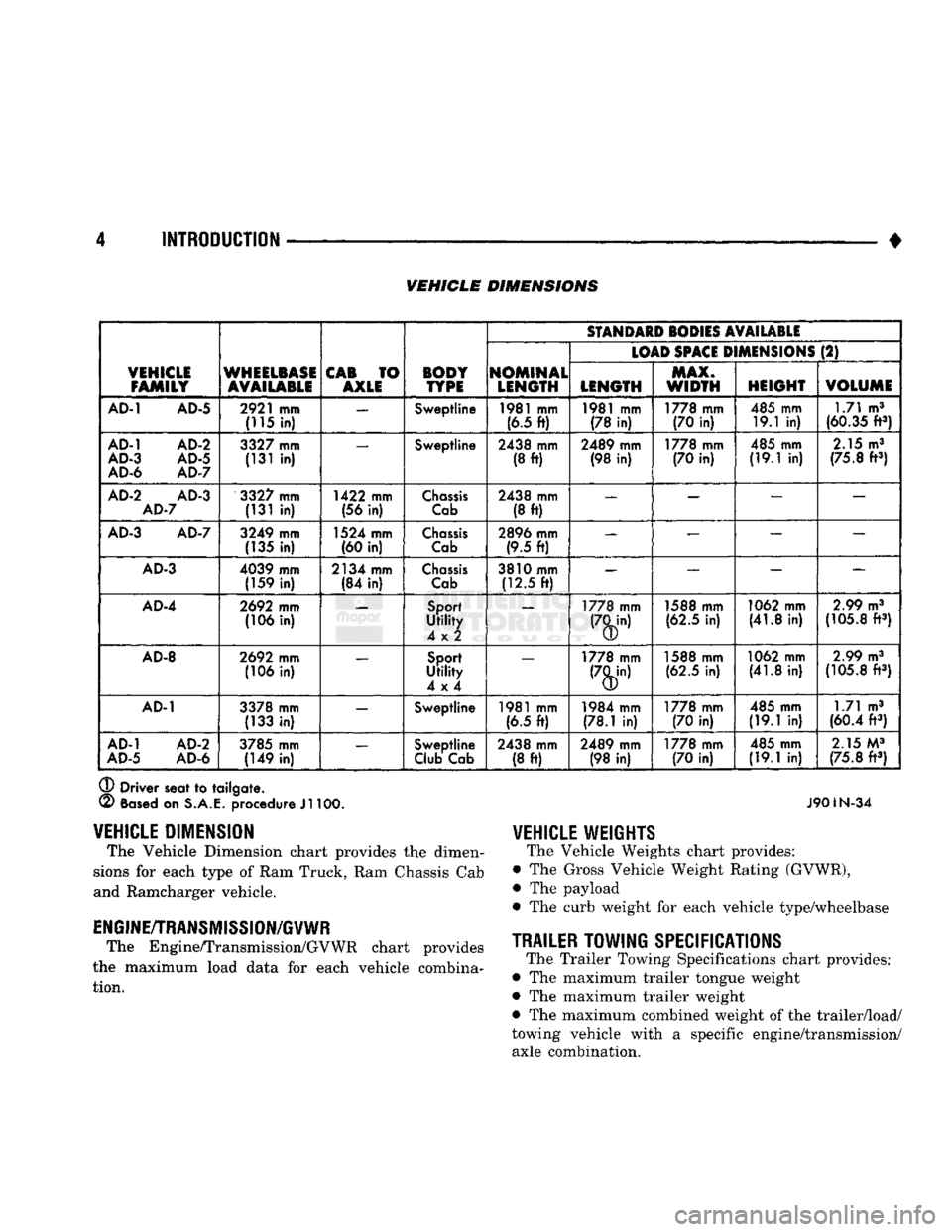
The Vehicle Dimension chart provides
the
dimen
sions
for
each type
of
Ram Truck, Ram Chassis Cab
and Ramcharger vehicle.
ENGINE/TRANSMISSION/GVWR
The Engine/Transmission/GVWR chart provides
the maximum load data
for
each vehicle combina tion.
Page 234 of 1502
BRAKES
5 - 47
(8) Disengage and remove adjuster screw assembly
from brakeshoes.
(9) Remove brake shoe retainers, springs and pins
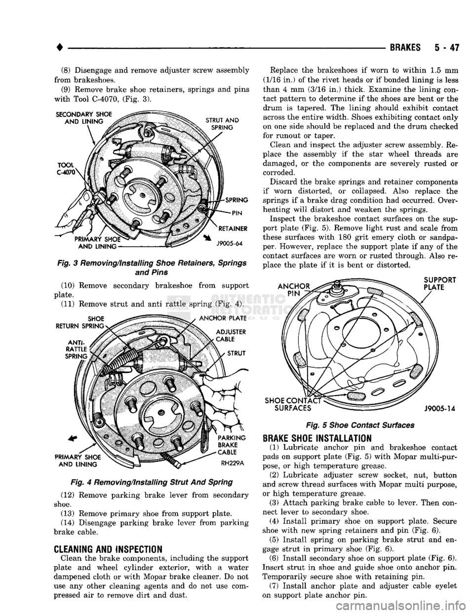
with Tool C-4070, (Fig. 3). Fig. 3 Removing/Installing Shoe Retainers, Springs
and Pins (10) Remove secondary brakeshoe from support
plate. (11) Remove strut and anti rattle spring (Fig. 4).
Fig. 4 Removing/Installing Strut And Spring
(12) Remove parking brake lever from secondary
shoe.
(13) Remove primary shoe from support plate.
(14) Disengage parking brake lever from parking
brake cable.
CLEANING AND INSPECTION
Clean the brake components, including the support
plate and wheel cylinder exterior, with a water dampened cloth or with Mopar brake cleaner. Do not
use any other cleaning agents and do not use com
pressed air to remove dirt and dust. Replace the brakeshoes if worn to within 1.5 mm
(1/16 in.) of the rivet heads or if bonded lining is less
than 4 mm (3/16 in.) thick. Examine the lining con
tact pattern to determine if the shoes are bent or the drum is tapered. The lining should exhibit contact across the entire width. Shoes exhibiting contact only
on one side should be replaced and the drum checked
for runout or taper.
Clean and inspect the adjuster screw assembly. Re
place the assembly if the star wheel threads are damaged, or the components are severely rusted or corroded.
Discard the brake springs and retainer components
if worn distorted, or collapsed. Also replace the springs if a brake drag condition had occurred. Over
heating will distort and weaken the springs. Inspect the brakeshoe contact surfaces on the sup
port plate (Fig. 5). Remove light rust and scale from
these surfaces with 180 grit emery cloth or sandpa
per. However, replace the support plate if any of the contact surfaces are worn or rusted through. Also re
place the plate if it is bent or distorted.
Fig. 5 Shoe Contact Surfaces
BRAKE
SHOE INSTALLATION
(1) Lubricate anchor pin and brakeshoe contact
pads on support plate (Fig. 5) with Mopar multi-pur
pose,
or high temperature grease. (2) Lubricate adjuster screw socket, nut, button
and screw thread surfaces with Mopar multi purpose,
or high temperature grease. (3) Attach parking brake cable to lever. Then con
nect lever to secondary shoe. (4) Install primary shoe on support plate. Secure
shoe with new spring retainers and pin (Fig. 6). (5) Install spring on parking brake strut and en
gage strut in primary shoe (Fig. 6). (6) Install secondary shoe on support plate (Fig. 6).
Insert strut in shoe and guide shoe onto anchor pin.
Temporarily secure shoe with retaining pin. (7) Install anchor plate and adjuster cable eyelet
on support plate anchor pin.
Page 239 of 1502
5
- 52
BRAKES
•
BRAKE
DRUM
REMOVAL
(1) Raise and support vehicle.
(2) Remove wheel and tire assembly.
(3) Remove axle shaft nuts, washers and cones.
Strike axle shaft in center with copper or dead blow
hammer to loosen retaining cones.
(4) Remove axle shaft.
(5) Remove outer hub nut.
(6)
Straighten and remove lock washer.
(7) Remove inner nut and bearing.
(8) Remove drum. If drum is difficult to remove,
retract brakeshoes as follows: (a) Remove rear plug from access hole in support
plate. (b) Insert a thin releasing tool (or screwdriver)
into access hole and push self adjusting lever away
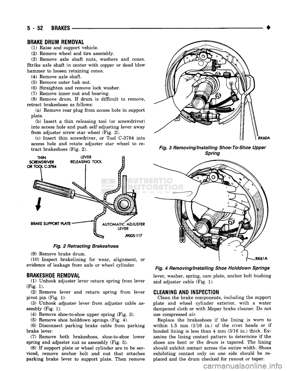
from adjuster screw star wheel (Fig. 2). (c) Insert thin screwdriver, or Tool C-3784 into
access hole and rotate adjuster star wheel to re
tract brakeshoes (Fig. 2).
Fig.
2 Retracting
Brakeshoes
(9) Remove brake drum.
(10) Inspect brakelining for wear, alignment, or
evidence of leakage from axle or wheel cylinder.
BRAKESHOE
REMOVAL
(1) Unhook adjuster lever return spring from lever
(Fig. 1). (2) Remove lever and return spring from lever
pivot pin (Fig. 1). (3) Unhook adjuster lever from adjuster cable as
sembly (Fig. 1). (4) Remove shoe-to-shoe upper spring (Fig. 3).
(5)
Remove shoe holddown springs (Fig. 4).
(6)
Disconnect parking brake cable from parking
brake lever. (7) Remove both brakeshoes, shoe-to-shoe lower
spring and adjuster nut as assembly (Fig. 5). (8) If support plate or wheel cylinder are to be ser
viced, remove anchor bolt and nut that attaches
parking brake lever to support plate. Then remove
RK60A
Fig.
3 Removing/Installing
Shoe-To-Shoe
Upper
Spring
Fig.
4 Removing/Installing
Shoe
Holddown
Springs
lever, washer, spring, cam plate, anchor bolt bushing and adjuster cable (Fig. 1).
CLEANING AND INSPECTION
Clean the brake components, including the support
plate and wheel cylinder exterior, with a water dampened cloth or with Mopar brake cleaner. Do not
use compressed air. Replace the brakeshoes if the lining is worn to
within 1.5 mm (1/16 in.) of the rivet heads or if
bonded lining is less than 4 mm (3/16 in.) thick. Ex amine the lining contact pattern to determine if the
shoes are bent or the drum is tapered. The lining
should exhibit contact across the entire width. Shoes
exhibiting contact only on one side should be re
placed and the drum checked for runout or taper.
Page 316 of 1502
•
COOLING
SYSTEM
7 - 45 (3) Rotate socket/wrench counterclockwise. Install
belt over tensioner pulley. Let tensioner rotate back into place. Remove wrench. Be sure belt is properly
seated on all pulleys.
5«9L
DIESEL ENGINE
REMOVAL
Drive belts on diesel engines are equipped with a
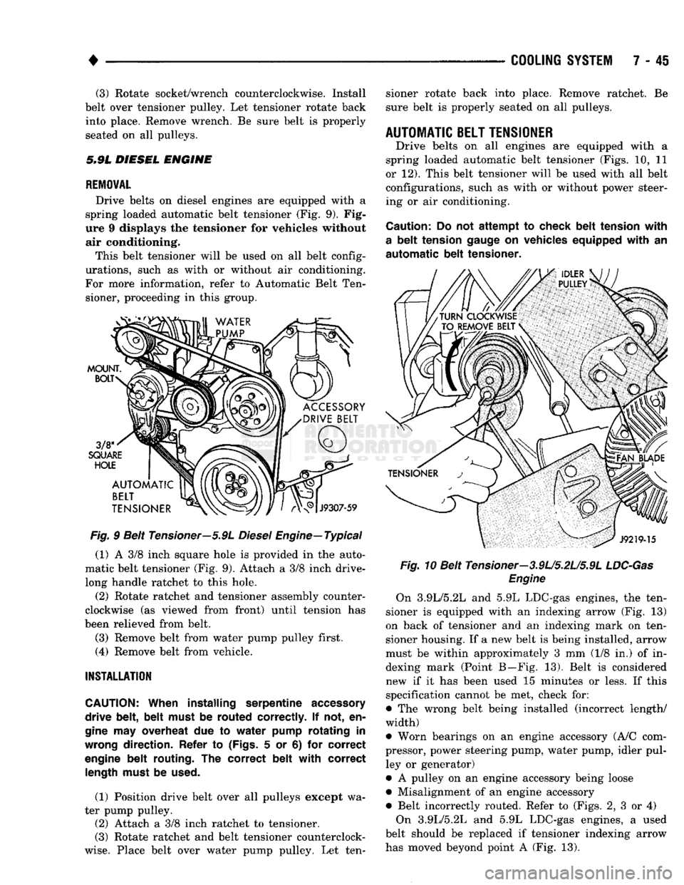
spring loaded automatic belt tensioner (Fig. 9). Fig
ure 9 displays the tensioner for vehicles without air conditioning.
This belt tensioner will be used on all belt config
urations, such as with or without air conditioning.
For more information, refer to Automatic Belt Ten sioner, proceeding in this group.
Fig.
9 Belt Tensioner—5.9L
Diesel
Engine—Typical
(1) A 3/8 inch square hole is provided in the auto
matic belt tensioner (Fig. 9). Attach a 3/8 inch drive-
long handle ratchet to this hole.
(2) Rotate ratchet and tensioner assembly counter
clockwise (as viewed from front) until tension has
been relieved from belt.
(3) Remove belt from water pump pulley first.
(4) Remove belt from vehicle.
INSTALLATION
CAUTION:
When installing serpentine
accessory
drive belt, belt must
be
routed correctly.
If not, en
gine
may
overheat
due to
water pump rotating
in
wrong
direction. Refer
to
(Figs.
5 or 6) for
correct
engine
belt routing.
The
correct belt with correct
length
must
be
used.
(1) Position drive belt over all pulleys except wa
ter pump pulley. (2) Attach a 3/8 inch ratchet to tensioner.
(3) Rotate ratchet and belt tensioner counterclock
wise.
Place belt over water pump pulley. Let ten sioner rotate back into place. Remove ratchet. Be
sure belt is properly seated on all pulleys.
AUTOMATIC
BELT
TENSIONER
Drive belts on all engines are equipped with a
spring loaded automatic belt tensioner (Figs. 10, 11
or 12). This belt tensioner will be used with all belt configurations, such as with or without power steer
ing or air conditioning.
Caution:
Do not
attempt
to
check belt tension with
a
belt tension
gauge
on
vehicles equipped with
an
automatic
belt tensioner. Fig.
10 Belt Tensioner—3.9U5.2U5.9L
LDC-Gas
Engine
On 3.9L/5.2L and 5.9L LDC-gas engines, the ten
sioner is equipped with an indexing arrow (Fig. 13)
on back of tensioner and an indexing mark on ten
sioner housing. If a new belt is being installed, arrow
must be within approximately 3 mm (1/8 in.) of in dexing mark (Point B—Fig. 13). Belt is considered
new if it has been used 15 minutes or less. If this
specification cannot be met, check for:
• The wrong belt being installed (incorrect length/
width)
• Worn bearings on an engine accessory (A/C com
pressor, power steering pump, water pump, idler pul ley or generator)
• A pulley on an engine accessory being loose
• Misalignment of an engine accessory
• Belt incorrectly routed. Refer to (Figs. 2, 3 or 4) On 3.9L/5.2L and 5.9L LDC-gas engines, a used
belt should be replaced if tensioner indexing arrow
has moved beyond point A (Fig. 13).
Page 355 of 1502
8D
- 4
IGNITION
SYSTEMS
•
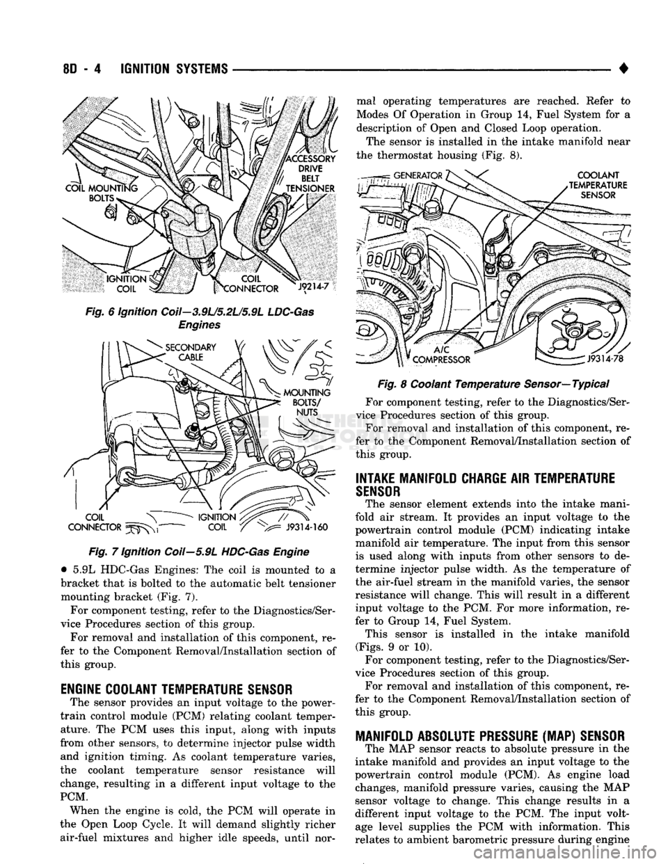
Fig. 6 ignition Coil—3.9L/5.2L/5.9L
LDC-Gas
Engines Fig. 7 Ignition Coil—5.9L
HDC-Gas
Engine
• 5.9L HDC-Gas Engines: The coil is mounted to a
bracket that is bolted to the automatic belt tensioner mounting bracket (Fig. 7).
For component testing, refer to the Diagnostics/Ser
vice Procedures section of this group.
For removal and installation of this component, re
fer to the Component Removal/Installation section of
this group.
ENGINE COOLANT TEMPERATURE
SENSOR
The sensor provides an input voltage to the power-
train control module (PCM) relating coolant temper ature. The PCM uses this input, along with inputs
from other sensors, to determine injector pulse width and ignition timing. As coolant temperature varies,
the coolant temperature sensor resistance will
change, resulting in a different input voltage to the
PCM. When the engine is cold, the PCM will operate in
the Open Loop Cycle. It will demand slightly richer air-fuel mixtures and higher idle speeds, until nor mal operating temperatures are reached. Refer to
Modes Of Operation in Group 14, Fuel System for a
description of Open and Closed Loop operation.
The sensor is installed in the intake manifold near
the thermostat housing (Fig. 8).
Fig. 8 Coolant Temperature Sensor—Typical
For component testing, refer to the Diagnostics/Ser
vice Procedures section of this group. For removal and installation of this component, re
fer to the Component Removal/Installation section of
this group.
INTAKE MANIFOLD CHARGE
AIR
TEMPERATURE
SENSOR
The sensor element extends into the intake mani
fold air stream. It provides an input voltage to the
powertrain control module (PCM) indicating intake
manifold air temperature. The input from this sensor is used along with inputs from other sensors to de
termine injector pulse width. As the temperature of
the air-fuel stream in the manifold varies, the sensor
resistance will change. This will result in a different input voltage to the PCM. For more information, re
fer to Group 14, Fuel System. This sensor is installed in the intake manifold
(Figs.
9 or 10). For component testing, refer to the Diagnostics/Ser
vice Procedures section of this group. For removal and installation of this component, re
fer to the Component Removal/Installation section of
this group.
MANIFOLD ABSOLUTE
PRESSURE
(MAP)
SENSOR
The MAP sensor reacts to absolute pressure in the
intake manifold and provides an input voltage to the
powertrain control module (PCM). As engine load changes, manifold pressure varies, causing the MAP
sensor voltage to change. This change results in a
different input voltage to the PCM. The input volt age level supplies the PCM with information. This
relates to ambient barometric pressure during engine
Page 357 of 1502
8D
- 6
IGNITION
SYSTEMS
• the position of the throttle blade changes, the resis
tance of the sensor changes.
The PCM supplies approximately 5 volts to the
sensor. The sensor output voltage (input signal to the
PCM) represents the throttle blade position. The
PCM receives an input signal voltage from the sen sor. This will vary in an approximate range of from 1
volt at minimum throttle opening (idle), to 4 volts at
wide open throttle. Along with inputs from other sen
sors,
the PCM uses the sensor input to determine
current engine operating conditions. It also will ad
just fuel injector pulse width and ignition timing.
For component testing, refer to the Diagnostics/Ser
vice Procedures section of this group.
For removal and installation of this component, re
fer to the Component Removal/Installation section of
this group.
MANIFOLD ABSOLUTE
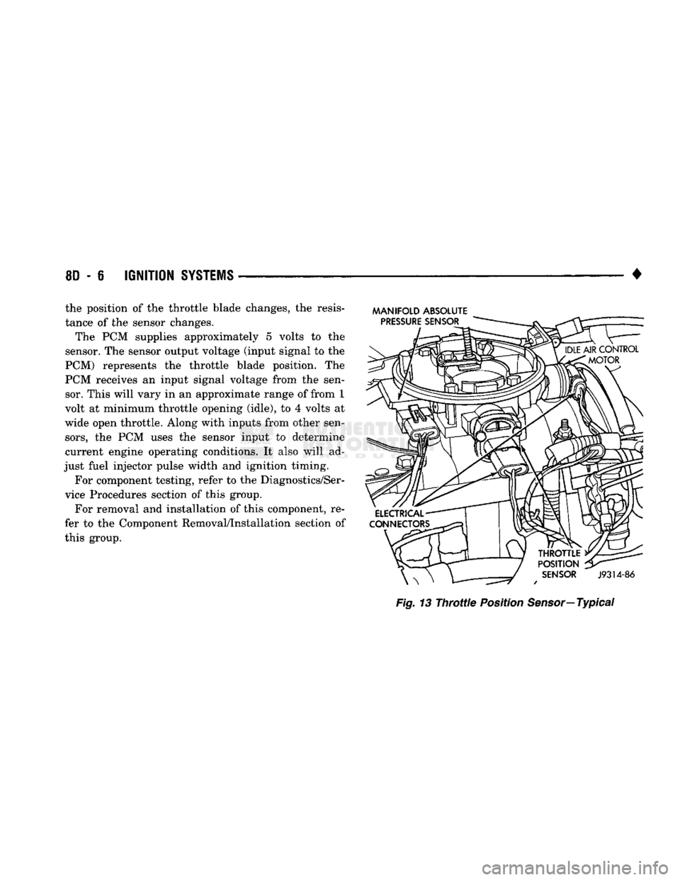
Fig.
13
Throttle
Position
Sensor—
Typical
Page 387 of 1502
8E
- 6
INSTRUMENT PANEL
AND
GAUGES
•
(5)
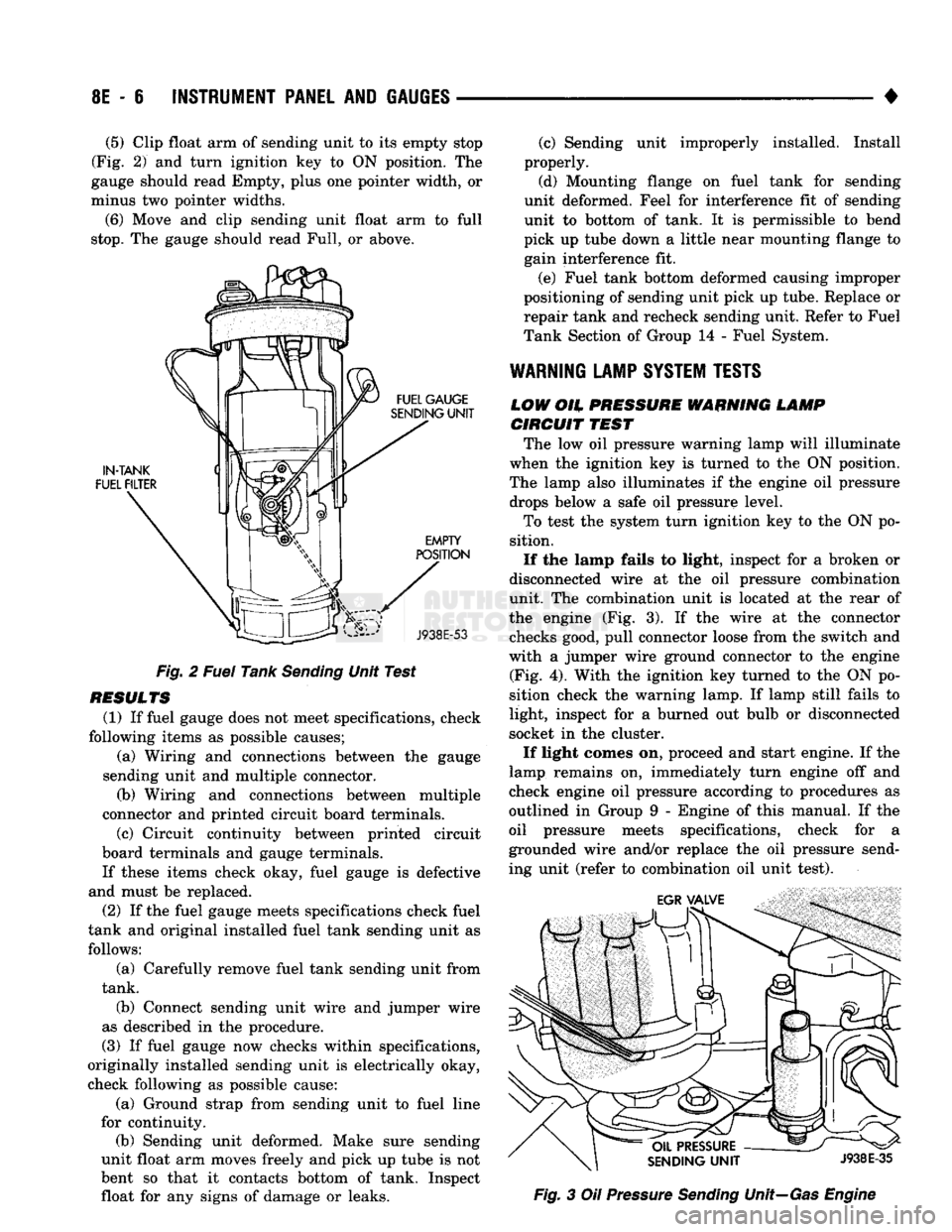
Clip float arm of sending unit to its empty stop
(Fig. 2) and turn ignition key to ON position. The
gauge should read Empty, plus one pointer width, or
minus two pointer widths.
(6) Move and clip sending unit float arm to full
stop.
The gauge should read Full, or above.
Fig. 2 Fuel Tank Sending Unit Test
RESULTS (1) If fuel gauge does not meet specifications, check
following items as possible causes; (a) Wiring and connections between the gauge
sending unit and multiple connector. (b) Wiring and connections between multiple
connector and printed circuit board terminals.
(c) Circuit continuity between printed circuit
board terminals and gauge terminals.
If these items check okay, fuel gauge is defective
and must be replaced.
(2) If the fuel gauge meets specifications check fuel
tank and original installed fuel tank sending unit as follows:
(a) Carefully remove fuel tank sending unit from
tank.
(b) Connect sending unit wire and jumper wire
as described in the procedure.
(3) If fuel gauge now checks within specifications,
originally installed sending unit is electrically okay,
check following as possible cause:
(a) Ground strap from sending unit to fuel line
for continuity. (b) Sending unit deformed. Make sure sending
unit float arm moves freely and pick up tube is not
bent so that it contacts bottom of tank. Inspect float for any signs of damage or leaks. (c) Sending unit improperly installed. Install
properly.
(d) Mounting flange on fuel tank for sending
unit deformed. Feel for interference fit of sending
unit to bottom of tank. It is permissible to bend
pick up tube down a little near mounting flange to gain interference fit.
(e) Fuel tank bottom deformed causing improper
positioning of sending unit pick up tube. Replace or
repair tank and recheck sending unit. Refer to Fuel
Tank Section of Group 14 - Fuel System.
WARNING
LAMP
SYSTEM
TESTS
LOW
OH.
PRESSURE WARNING LAMP CIRCUIT
TEST
The low oil pressure warning lamp will illuminate
when the ignition key is turned to the ON position.
The lamp also illuminates if the engine oil pressure drops below a safe oil pressure level.
To test the system turn ignition key to the ON po
sition.
If the lamp fails to light, inspect for a broken or
disconnected wire at the oil pressure combination
unit. The combination unit is located at the rear of
the engine (Fig. 3). If the wire at the connector checks good, pull connector loose from the switch and
with a jumper wire ground connector to the engine (Fig. 4). With the ignition key turned to the ON po
sition check the warning lamp. If lamp still fails to
light, inspect for a burned out bulb or disconnected
socket in the cluster.
If light comes on, proceed and start engine. If the
lamp remains on, immediately turn engine off and
check engine oil pressure according to procedures as
outlined in Group 9 - Engine of this manual. If the
oil pressure meets specifications, check for a
grounded wire and/or replace the oil pressure send
ing unit (refer to combination oil unit test). Fig. 3 Oil Pressure Sending Unit—Gas Engine
Page 606 of 1502
•
ENGINES ENGINES
9 - 1
CONTENTS
page page
3.9L
ENGINE SERVICE PROCEDURES
17 5.9L
ENGINE SERVICE PROCEDURES
77
5.2L
ENGINE SERVICE PROCEDURES
47
ENGINE DIAGNOSIS
5
5.9L
(DIESEL) ENGINE SERVICE PROCEDURES
. 107
STANDARD SERVICE PROCEDURES
1
STANDARD SERVICE PROCEDURES INDEX
page
Engine
Performance 2
Form-ln-Place
Gaskets
1
Honing
Cylinder
Bores
2
FORM-IN-PLACE GASKETS
There are several places where form-in-place gas
kets are used on the engine. DO NOT use form-in-
place gasket material unless specified. Care must
be taken when applying form-in-place gaskets. Bead
size,
continuity and location are of great importance.
Too thin a bead can result in leakage while too much can result in spill-over. A continuous bead of the
proper width is essential to obtain a leak-free joint. Two types of form-in-place gasket materials are
used in the engine area (Mopar Silicone Rubber Ad
hesive Sealant and Mopar Gasket Maker). Each have different properties and cannot be used interchange ably.
MOPAR SILICONE RUBBER ADHESIWE
SEALANT
Mopar Silicone Rubber Adhesive Sealant, normally
black in color, is available in 3 ounce tubes. Moisture in the air causes the sealant material to cure. This
material is normally used on flexible metal flanges.
It has a shelf life of 1 year and will not properly cure
if over aged. Always inspect the package for the ex
piration date before use.
MOPAR
GASKET MAKER Mopar Gasket Maker, normally red in color, is
available in 6 cc tubes. This anaerobic type gasket
material cures in the absence of air when squeezed
between smooth machined metallic surfaces. It will not cure if left in the uncovered tube. DO NOT use on flexible metal flanges.
page
Hydrostatic
Lock
4
Measuring
with
Plastigage 3
Repair
Damaged
or Worn
Threads
. 4
SURFACE PREPARA
TION
Parts assembled with form-in-place gaskets may be
disassembled without unusual effort. In some in
stances, it may be necessary to lightly tap the part
with a mallet or other suitable tool to break the seal
between the mating surfaces. A flat gasket scraper may also be lightly tapped into the joint but care
must be taken not to damage the mating surfaces.
Scrape or wire brush all gasket surfaces to remove
all loose material. Inspect stamped parts to ensure
gasket rails are flat. Flatten rails with a hammer on a flat plate, if required. Gasket surfaces must be free
of oil and dirt. Make sure the old gasket material is
removed from blind attaching holes.
GASKET
APPLICATION
Assembling parts using a form-in-place gasket re
quires care.
Mopar Silicone Rubber Adhesive Sealant should be
applied in a continuous bead approximately 3 mm (0.12 inch) in diameter. All mounting holes must be
circled. For corner sealing, a 3 or 6 mm (1/8 or 1/4
inch) drop is placed in the center of the gasket con
tact area. Uncured sealant may be removed with a shop towel. Components should be torqued in place
while the sealant is still wet to the touch (within 10
minutes). The use of a locating dowel is recom
mended during assembly to prevent smearing the
material off location.
Mopar Gasket Maker should be applied sparingly
to one gasket surface. The sealant diameter should
be 1.Q0 mm (0.04 inch) or less. Be certain the mate-