1993 DODGE TRUCK gas mileage
[x] Cancel search: gas mileagePage 24 of 1502
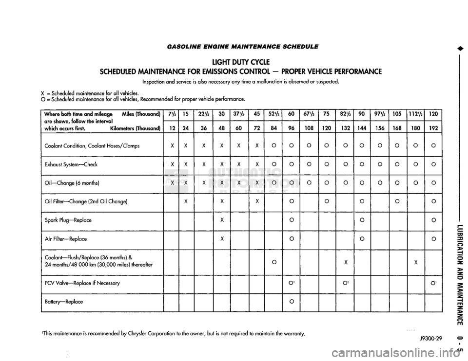
GASOLINE ENGINE MAINTENANCE SCHEDULE
LIGHT
DUTY
CYCLE
SCHEDULED
MAINTENANCE
FOR
EMISSIONS
CONTROL
-
PROPER
VEHICLE
PERFORMANCE
Inspection and service is also necessary any
rime
a
malfunction
is observed or suspected.
X
= Scheduled maintenance for all vehicles.
O
= Scheduled maintenance for all vehicles, Recommended for proper
vehicle
performance.
Where both
time
and mileage Miles (Thousand) are
shown,
follow the
interval
which
occurs
first. Kilometers (Thousand) 7'A
15
22'A
30
37'A
45
52'A
60
67'A
75
82'A
90 97'/2 105 112'A
120
Where both
time
and mileage Miles (Thousand)
are
shown,
follow the
interval
which
occurs
first. Kilometers (Thousand) 12 24
36 48
60 72 84 96 108 120
132 144 156 168 180 192
Coolant
Condition,
Coolant
Hoses/Clomps
X X X X X X
O O O O O
O O O
o
O
Exhaust
System—Check
X
X X X X
X
O O O
o
O
O O
o o o
Oil—Change
(6 months)
X X X X X X
O O O
o o
O O
o o
o
Oil Filter—Change (2nd Oil Change)
X
X X
o o
O
o
o
Spark
Plug—Replace
X
0
o o
Air
Filter—Replace
X
o
O
o
Coolant—Flush/Replace
(36 months) &
24
months/48 000 km
(30,000
miles)
thereafter
O
X
X
PCV
Valve—Replace if
Necessary
O'
O' O'
Battery—Replace
O
This maintenance is recommended by Chrysler Corporation to the owner, but is not
required
to
maintain
the
warranty.
Page 25 of 1502

0 - 6
LUBRICATION
AND
MAINTENANCE
GASOLINE ENGINE MAINTENANCE SCHEDULE
HEAVY
DUTY
CYCLE
Inspection and service is also necessary anytime
a
malfunction is observed or suspected.
When both
time
and mileage
are
Miles (Thousand)
shewn,
follow
the
interval
which occurs first. Kilometers (Thousand) 6
12 18 24
30 36 42 48 54
60 66 72
78
82V2
84 90
96
102 108
When both
time
and mileage
are
Miles (Thousand)
shewn,
follow
the
interval
which occurs first. Kilometers (Thousand) 9.6 19 29
38 48 58 67 77
85 96 106 116
125 132
135
145
154 164
174
Coolant
Condition, Coolant
Hoses/Clamps
X
X X X
X X X X
X X X X
X X X
X X X
Exhaust
System
—
Check
X X X X X X X X X X X
X X X X X
X X
Oil
—
Change
(6
Months)
X X X X X X X
X X
X
X
X
X X X
X X
X
Oil
Filter
—
Change (2nd
Oil
Change)
X X X X
X X
X X
X
Drive Belt Tension
—
Inspect
&
Adjust
X' X
X1
X X' X
Drive Belts (V-Type)
—
Replace
X
Air
Filter/Air
Pump
Air
Filter
—
Replace
X X X
X
Crankcase
Inlet
Air
Filter
(6 &
8
Cyl.
Eng.
Only)
—
Clean
X X
X X
Spark
Plug
—
Replace
X X X
Fuel
Filter
—
Replace as necessary
Coolant
—
Flush/Replace
(36
months)
& 24
months/48
000 km
(30,000
miles)
thereafter
X
EGR
Valve
&
Tube
—
Replace X2
EGR
Tube
—
Clean Passengers
X2
PCV
Valve
—
Replace X2
Vacuum
Emission
Components
—
Replace
X
Ignition Timing
—
Adjust
to
Specs,
as necessary X
Ignition Cables, Distributor Cap
&
Rotor
—
Replace
X
Manifold Heat Control Valve
—
Lubricate
X
Battery
—
Replace X
Oxygen
Sensor
—
Replace
X2
1 For California vehicles, this maintenance is recommended
by
Chrysler Motors
to the
owner but, is not
required
to
maintain the
warranty
on the
air
pump drive
belt.
2 Requires
Emission
Maintenance Reminder Light.
If
so equipped, these parts
are to be
replaced
at the
indicated mileage,
or
when the
emissions
maintenance reminded light remains on continuously
with
the key in the
"on" position, whichever occurs first.
J9100-20
DIESEL
ENGINE
MAINTENANCE
SCHEDULE
HEAVY
DUTY
CYCLE
Inspection
and
service
is
also
necessary
any
time
a
malfunction
is
observed
or
suspected.
Iff both
time
and distance Miles (Thousand)
are listed, use the
interval
that
ends
first. Kilometers (Thousand) 6
12
18 24
30 36 42
4S
54
60 66
72 78
84 90 96
102 108
Iff both
time
and distance Miles (Thousand)
are listed, use the
interval
that
ends
first. Kilometers (Thousand) 9,6 19
29
38 48 58 67
77
85 96 106
116 125 135 145 154
164 174
Coolant
Condition, Coolant
Hoses/Clamps
(12 months)
Coolant
Flush/Replace (36 months) & 24 months/
48 000 km
(30,000
miles)
thereafter
O
Oil—Change
(6 months)
X X X
X X X
X X X X X
X X X X X X
X
Oil Filter—Replace (Every Oil Change)
X X X
X X X
X X
X X X
X
X X X X
X X
Drive Belts—Replace
As
Necessary
X X
X X X X
Air Filter—Replace
X X
X X
Air Filter—Clean (California Only) e
®
• •
Air
Filter
Canister—Clean
o o o
o
Fuel Filter—Service When Necessary
Injection
Pump
Timing & Engine Idle Speed—
Check
& Adjust
©
• 9 • • •
Underhood Rubber/Plastic Components—Inspect/Replace • • • • •
X
— All vehicles
O
— All
vehicles
except
California.
Recommended
for
California.
•
— California only.
Recommended
for all vehicles.
Page 111 of 1502
2
- 58
FRONT
SUSPENSION
AND
AXLE
•
C-4366-2
C-4366-1
RH432A
C-4212-L
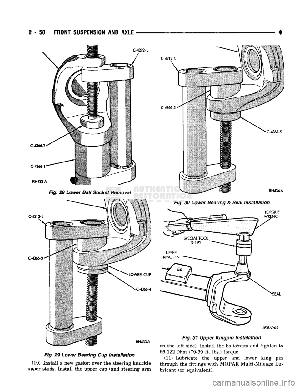
Fig.
28
Lower
Ball
Socket
Removal
C-4212-L
C-4366-3
C-4366-4
RH433A
Fig.
29
Lower
Bearing Cup Installation
(10) Install a new gasket over the steering knuckle
upper studs. Install the upper cap (and steering arm
C-4212-L
C-4366-3
RH434A
Fig.
30
Lower
Bearing &
Seal
Installation
TORQUE
WRENCH
SEAL
J9202-66
Fig.
31 Upper
Kingpin
Installation
on the left side). Install the bolts/nuts and tighten to
96-122 N*m (70-90 ft. lbs.) torque. (11) Lubricate the upper and lower king pin
through the fittings with MOPAR Multi-Mileage Lu
bricant (or equivalent).
Page 218 of 1502
•
BRAKES
5 - 31 board lining. Also check condition of the caliper pis
ton dust boot. If leakage is evident or if the boot is
cut, torn, or damaged in any way, it will be necessary to overhaul the caliper.
Remove the O-ring from the caliper adapter and clean
the slide surfaces of the adapter and the machined ways on the caliper with a wire brush and sandpaper.
DISC
BRAKESHOE
INSTALLATION
(1) Install inboard brakeshoe in adapter (Fig. 8).
(2) If new brakeshoes are being installed, remove
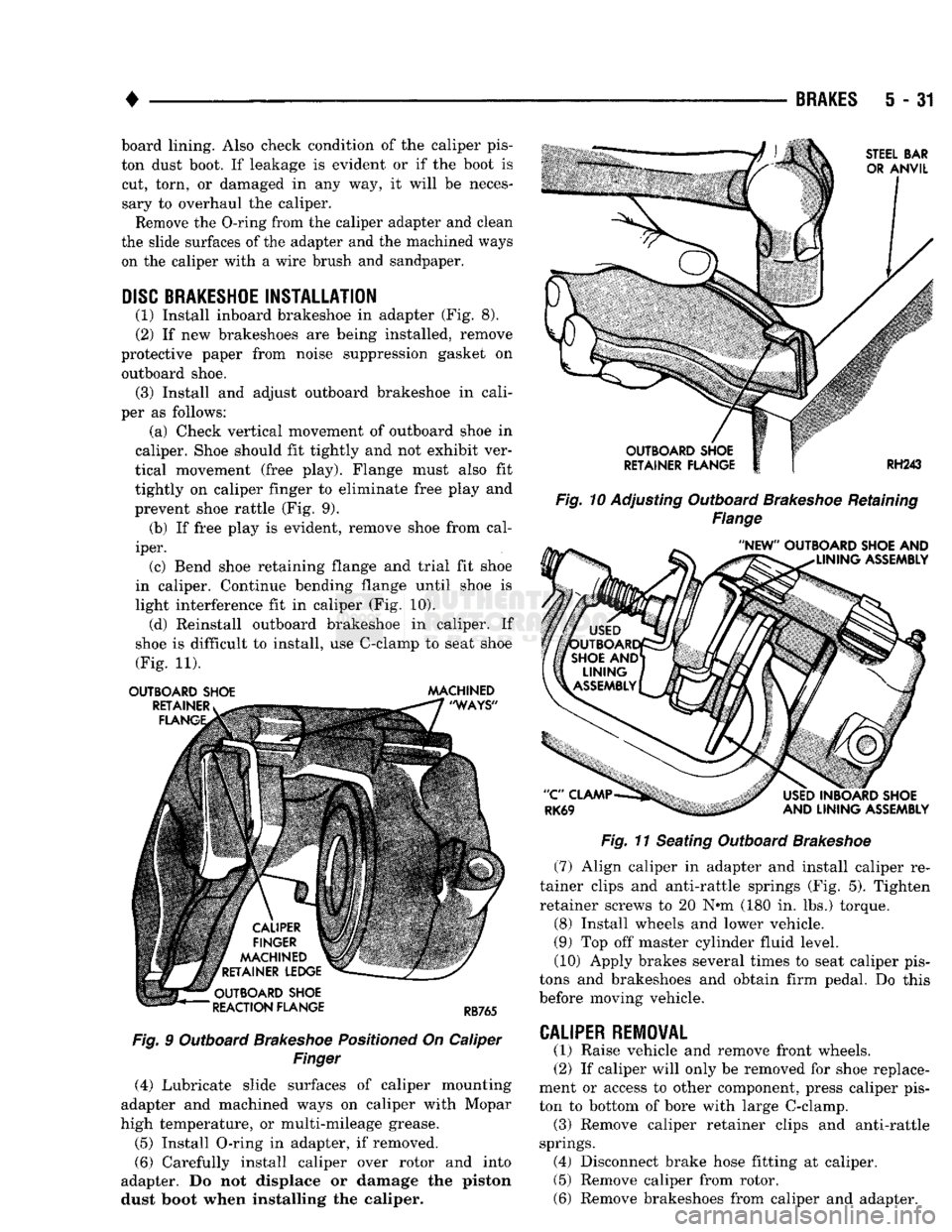
protective paper from noise suppression gasket on outboard shoe. (3) Install and adjust outboard brakeshoe in cali
per as follows: (a) Check vertical movement of outboard shoe in
caliper. Shoe should fit tightly and not exhibit ver
tical movement (free play). Flange must also fit
tightly on caliper finger to eliminate free play and
prevent shoe rattle (Fig. 9). (b) If free play is evident, remove shoe from cal
iper. (c) Bend shoe retaining flange and trial fit shoe
in caliper. Continue bending flange until shoe is
light interference fit in caliper (Fig. 10). (d) Reinstall outboard brakeshoe in caliper. If
shoe is difficult to install, use C-clamp to seat shoe
(Fig. 11).
OUTBOARD SHOE MACHINED
Fig.
9 Outboard
Brakeshoe
Positioned
On Caliper
Finger
(4) Lubricate slide surfaces of caliper mounting
adapter and machined ways on caliper with Mopar
high temperature, or multi-mileage grease.
(5) Install O-ring in adapter, if removed.
(6) Carefully install caliper over rotor and into
adapter. Do not displace or damage the piston dust boot when installing the caliper.
Fig. 10
Adjusting Outboard
Brakeshoe
Retaining
Flange
Fig.
11 Seating Outboard
Brakeshoe
(7) Align caliper in adapter and install caliper re
tainer clips and anti-rattle springs (Fig. 5). Tighten
retainer screws to 20 N«m (180 in. lbs.) torque.
(8) Install wheels and lower vehicle.
(9) Top off master cylinder fluid level. (10) Apply brakes several times to seat caliper pis
tons and brakeshoes and obtain firm pedal. Do this
before moving vehicle.
CALIPER
REMOVAL
(1) Raise vehicle and remove front wheels.
(2) If caliper will only be removed for shoe replace
ment or access to other component, press caliper pis
ton to bottom of bore with large C-clamp. (3) Remove caliper retainer clips and anti-rattle
springs. (4) Disconnect brake hose fitting at caliper. (5) Remove caliper from rotor.
(6) Remove brakeshoes from caliper and adapter.
Page 270 of 1502

•
CLUTCH
6-17
CLUTCH PEDAL INSTALLATION
(1) Lubricate pedal shaft, pedal shaft bore and all
bushings with Mopar Multi Mileage grease. (2) Insert pedal pin into cylinder push rod. Then
position clutch pedal in support. (3) Slide pedal shaft through clutch pedal bore and
bushings. (4) Install bolt that retains pedal shaft in support.
(5) Secure push rod to pedal pin with wave washer,
flat washer and retaining ring.
FLYWHEEL SERVICE
Inspect the flywheel whenever the clutch disc,
cover and housing are removed for service. Check
condition of the flywheel face, hub, ring gear teeth,
and flywheel bolts. Minor scratches, burrs, or glazing on the flywheel
face can be scuff sanded with 180 grit emery cloth. However, the flywheel should be replaced if the disc
contact surface is severely scored, heat checked,
cracked, or obviously worn. Cleanup of minor flywheel scoring should be per
formed with surface grinding equipment. Remove
only enough material to reduce scoring (approximate
ly 0.001 - 0.003 in.). Heavy stock removal is not rec
ommended. Replace the flywheel if scoring is severe
and deeper than 0.076 mm (0.003 in.). Excessive
stock removal can result in flywheel cracking or
warpage after installation; it can also weaken the flywheel and interfere with proper clutch release. Check flywheel runout if misalignment is sus
pected. Runout should not exceed 0.08 mm (0.003
in.).
Measure runout at the outer edge of the fly
wheel face with a dial indicator. Mount the dial in
dicator on a stud installed in place of one of the
flywheel attaching bolts. Clean the crankshaft flange before mounting the
flywheel. Dirt and grease on the flange surface may cock the flywheel causing excessive runout. Check condition of the flywheel hub and attaching
bolts.
Replace the flywheel if the hub exhibits cracks in the area of the attaching bolt holes. Install new attaching bolts whenever the flywheel
is replaced and use Mopar Lock N' Seal, or Loctite
242 on replacement bolt threads.
Recommended flywheel bolt torques are:
• 75 N»m (55 ft. lbs.) for gas engine flywheels
• 137 N*m (101 ft. lbs.) for diesel flywheels Inspect the teeth on the starter ring gear. If the
teeth are worn or damaged, the flywheel should
be replaced as an assembly. This is the recom mended and preferred method of repair.
In cases where a new flywheel is not readily avail
able,
a replacement ring gear can be installed. How
ever, the following precautions must be observed to
avoid damaging the flywheel and replacement gear.
(a) Mark position of the old gear for alignment
reference on the flywheel. Use a scriber for this
purpose.
(b) Wear protective goggles or approved safety
glasses. Also wear heat resistent gloves when han
dling a heated ring gear. (c) Remove the old gear by cutting most of the
way through it (at one point) with an abrasive cut off wheel. Then complete removal with a cold chisel
or punch. (d) The ring gear is a shrink fit on the flywheel.
This means the gear must be expanded by heating in order to install it. The method of heating and expanding the gear is extremely important. Ev
ery surface of the gear must be heated at the same
time to produce uniform expansion. An oven or
similar enclosed heating device must be used. Tem
perature required for uniform expansion is 325-350° F.
CAUTION:
Never
use an
oxy/acetylene torch
to re
move
the old
gear,
or to
heat
and
expand
a new
gear.
The
high temperature
of the
torch flame
will
cause
localized heating
and
damage
the
flywheel.
In
addition,
using
the
torch
to
heat
a
replacement gear
will
cause uneven heating
and
expansion.
The
torch
flame
will
also
anneal
the
gear
teeth
resulting
in
rapid wear
and
damage
after
installation.
(e) The heated gear must be installed evenly to
avoid misalignment or distortion. A shop press and
suitable press plates should be used to install the
gear if at all possible.
(f) Be sure to wear eye and hand protection.
Heat resistent gloves and safety goggles are needed
for personal safety. Also use metal tongs, vise
grips,
or similar tools to position the gear as necessary for installation.
(g) Allow the flywheel and ring gear to cool
down before installation. Set the assembly on a
workbench and let it cool in normal shop air.
CAUTION:
Do not
use water,
or
compressed
air to
cool
the
flywheel.
The
rapid cooling produced
by
water
or
compressed
air can
distort,
or
crack
the
gear
and
flywheel.
Page 277 of 1502
7 - 6
COOLING
SYSTEM
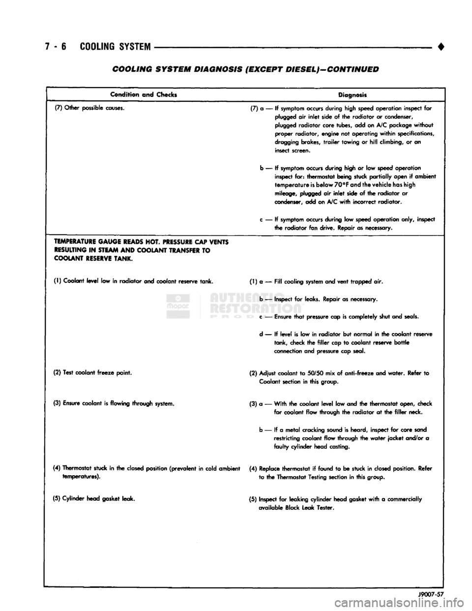
• COOLING SYSTEM DIAGNOSIS (EXCEPT DIESEL)—CONTINUED
Condition and Checks
Diagnosis
(7) Other possible
causes.
(7) a — If
symptom
occurs
during high speed operation inspect for
plugged
air
inlet
side of the radiator or condenser,
plugged
radiator core tubes, add on A/C package
without
proper radiator, engine not operating
within
specifications,
dragging
brakes,
trailer
towing or
hill
climbing, or an insect screen.
b — If
symptom
occurs
during high or low
speed
operation inspect for: thermostat being stuck
partially
open if ambient
temperature
is
below
70°F
and
the vehicle
has
high
mileage,
plugged
air
inlet
side of the radiator or
condenser, add on
A/C
with
incorrect radiator.
c
— If
symptom
occurs
during low
speed
operation only, inspect the radiator fan drive. Repair as necessary.
TEMPERATURE
GAUGE
READS
HOT.
PRESSURE
CAP
VENTS
RESULTING
IN
STEAM
AND
COOLANT
TRANSFER
TO
COOLANT
RESERVE
TANK.
(1) Coolant
level
low in radiator and coolant reserve tank. (1) a —
Fill
cooling
system
and vent trapped air.
b — Inspect for leaks. Repair as necessary.
c
—
Ensure
that
pressure cap
is
completely shut and
seals.
d
— If
level
is low in radiator but normal in the coolant reserve tank, check the
filler
cap to coolant reserve
bottle
connection and pressure cap seal.
(2) Test coolant
freeze
point. (2) Adjust coolant to
50/50
mix of
anti-freeze
and
water.
Refer to
Coolant
section in this group.
(3)
Ensure
coolant
is
flowing through system. (3) a — With the coolant
level
low and the thermostat open, check
for coolant flow through the radiator at the
filler
neck.
b — If a
metal
cracking
sound
is heard, inspect for core sand restricting coolant flow through the
water
jacket
and/or a
faulty
cylinder head casting.
(4) Thermostat stuck in the
closed
position
(prevalent
in cold ambient temperatures). (4) Replace thermostat if found to be stuck in
closed
position.
Refer
to the Thermostat Testing section in this group.
(5) Cylinder head gasket leak. (5) Inspect for leaking cylinder head gasket
with
a commercially
available Block Leak Tester.
J9007-57
Page 282 of 1502
•
COOLING
SYSTEM
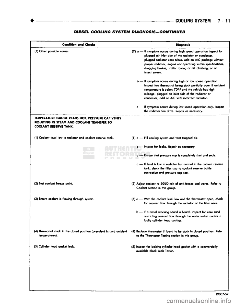
7-11 DIESEL COOLING SYSTEM DIAGNOSIS-CONTINUED
Condition and Chocks
Diagnosis
(7) Other possible
causes.
(7) a — If
symptom
occurs
during high speed operation inspect for
plugged
air
inlet
side of the radiator or condenser,
plugged
radiator core tubes, add on
A/C
package without
proper radiator, engine not operating
within
specifications,
dragging
brakes,
trailer
towing or
hill
climbing, or an insect screen.
b — If
symptom
occurs
during
high
or low speed operation inspect for: thermostat being stuck
partially
open if ambient
temperature
is
below 70°F
and
the vehicle
has
high
mileage,
plugged
air
inlet
side of the radiator or
condenser, add on
A/C
with
incorrect radiator.
c
— If
symptom
occurs
during low
speed
operation only, inspect the radiator fan drive. Repair
as
necessary.
TEMPERATURE
GAUGE
READS
HOT.
PRESSURE
CAP VENTS
RESULTING
IN
STEAM
AND COOLANT
TRANSFER
TO
COOLANT
RESERVE
TANK.
(1)
Coolant
level
low in radiator and coolant reserve tank. (1) a —
Fill
cooling
system
and vent trapped air.
b — Inspect for leaks. Repair as necessary.
c
—
Ensure
that
pressure cap
is
completely shut and
seals.
d
— If
level
is low in radiator but normal in the coolant reserve tank, check the
filler
cap to coolant reserve
bottle
connection and pressure cap seal.
(2) Test coolant
freeze
point. (2) Adjust coolant to 50/50 mix of
anti-freeze
and
water.
Refer to
Coolant
section
in this group.
(3)
Ensure
coolant
is
flowing through system. (3) a — With the coolant
level
low and the thermostat open, check
for coolant flow through the radiator at the
filler
neck.
b — If a
metal
cracking
sound
is
heard, inspect for core sand restricting coolant flow through the
water
jacket
and/or a
faulty
cylinder head casting.
(4) Thermostat stuck in the
closed
position (prevalent in cold ambient temperatures). (4) Replace thermostat if found to be stuck in
closed
position. Refer
to the Thermostat Testing section in this group.
(5) Cylinder head gasket leak. (5) Inspect for leaking cylinder head
gasket
with
a commercially
available Block Leak Tester.
J9007-57
Page 352 of 1502
•
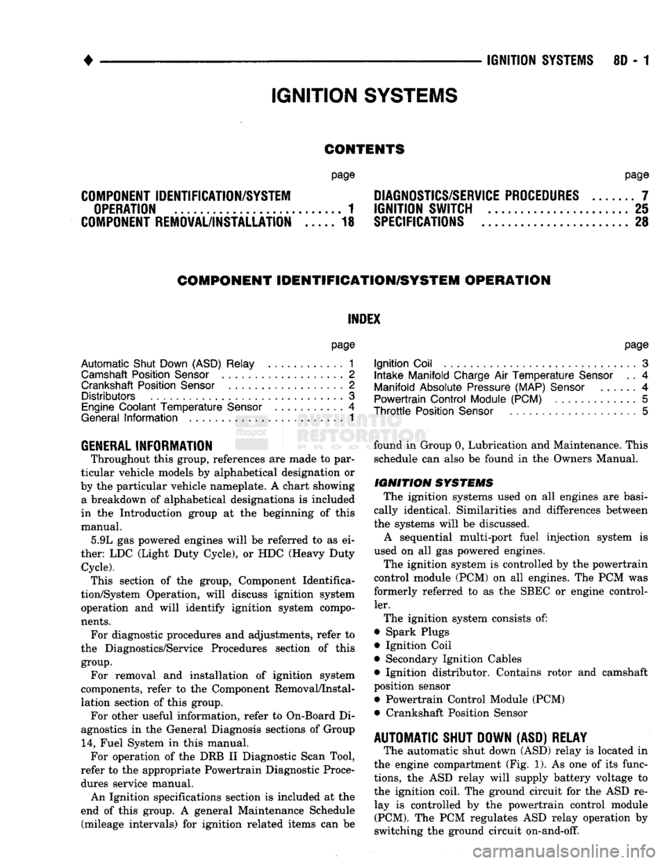
IGNITION
SYSTEMS
8D
- 1
CONTENTS
page page
COMPONENT IDENTIFICATION/SYSTEM DIAGNOSTICS/SERVICE PROCEDURES
7
OPERATION
1
IGNITION SWITCH
25
COMPONENT REMOVAL/INSTALLATION
..... 18
SPECIFICATIONS
28
COMPONENT
IDENTIFICATION/SYSTEM OPERATION
INDEX
page
Automatic
Shut Down (ASD) Relay
1
Camshaft Position Sensor
2
Crankshaft Position Sensor
2
Distributors
3
Engine Coolant
Temperature
Sensor
...........
4
General
Information
1
page
Ignition
Coil
3
Intake
Manifold Charge
Air
Temperature
Sensor
. . 4
Manifold Absolute Pressure (MAP) Sensor
4
Powertrain
Control
Module (PCM)
. 5
Throttle
Position Sensor
5
GENERAL
INFORMATION
Throughout this group, references
are
made
to
par
ticular vehicle models
by
alphabetical designation
or
by
the
particular vehicle nameplate.
A
chart showing a breakdown
of
alphabetical designations
is
included
in
the
Introduction group
at the
beginning
of
this
manual. 5.9L
gas
powered engines will
be
referred
to as ei
ther: LDC (Light Duty Cycle),
or
HDC (Heavy Duty Cycle). This section
of the
group, Component Identifica
tion/System Operation, will discuss ignition system operation
and
will identify ignition system compo
nents.
For diagnostic procedures
and
adjustments, refer
to
the Diagnostics/Service Procedures section
of
this
group.
For removal
and
installation
of
ignition system
components, refer
to the
Component Removal/Instal
lation section
of
this group. For other useful information, refer
to
On-Board
Di
agnostics
in the
General Diagnosis sections
of
Group
14,
Fuel System
in
this manual. For operation
of the DRB II
Diagnostic Scan Tool,
refer
to the
appropriate Powertrain Diagnostic Proce
dures service manual.
An Ignition specifications section
is
included
at the
end
of
this group.
A
general Maintenance Schedule (mileage intervals)
for
ignition related items
can be
found
in
Group
0,
Lubrication and Maintenance. This
schedule
can
also
be
found
in the
Owners Manual.
IGNITION
SYSTEMS
The ignition systems used
on all
engines
are
basi
cally identical. Similarities
and
differences between
the systems will
be
discussed.
A sequential multi-port fuel injection system
is
used
on all gas
powered engines.
The ignition system
is
controlled
by the
powertrain
control module (PCM)
on all
engines.
The
PCM
was
formerly referred
to as the
SBEC
or
engine control ler.
The ignition system consists
of:
• Spark Plugs
• Ignition Coil
• Secondary Ignition Cables
• Ignition distributor. Contains rotor
and
camshaft
position sensor • Powertrain Control Module (PCM)
• Crankshaft Position Sensor
AUTOMATIC SHUT DOWN (ASD) RELAY
The automatic shut down (ASD) relay
is
located
in
the engine compartment (Fig.
1). As one of its
func
tions,
the ASD
relay will supply battery voltage
to
the ignition coil.
The
ground circuit
for the
ASD
re
lay
is
controlled
by the
powertrain control module (PCM).
The PCM
regulates
ASD
relay operation
by
switching
the
ground circuit on-and-off.
IGNITION
SYSTEMS