1993 DODGE TRUCK warning lights
[x] Cancel search: warning lightsPage 15 of 1502
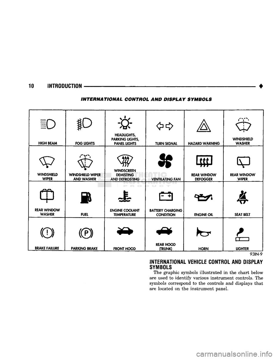
10 INTRODUCTION
•
INTERNATIONAL CONTROL AND DISPLAY SYMBOLS
ID
HIGH
BEAM P
FOG UGHTS -&
HEADLIGHTS,
PARKING UGHTS, PANEL UGHTS TURN SIGNAL A
HAZARD WARNING WINDSHIELD
WASHER
WINDSHIELD WIPER WINDSHIELD WIPER
AND WASHER
AND DEFROSTING *
VENTILATING
FAN 8
M f
REAR
WINDOW DEFOGGER
sp
REARWINLX)W WIPER
CD
l
m
REAR
WINDOW WASHER FUEL ENGINE COOLANT
TEMPERATURE BATTERY CHARGING
CONDITION ENGINE OIL
SEAT
BELT
(©) (®) ky
11 J
LIGHTER
BRAKE
FAILURE
PARKING
BRAKE
FRONT HOOD
REAR
HOOD
(TRUNK)
HORN
11 J
LIGHTER
93IN-9
INTERNATIONAL VEHICLE CONTROL AND DISPLAY
SYMBOLS
The graphic symbols illustrated in the chart below
are used to identify various instrument controls. The
symbols correspond to the controls and displays that are located on the instrument panel.
Page 28 of 1502
•
LUBRICATION AND MAINTENANCE
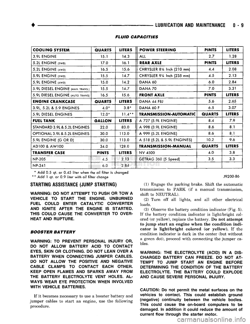
0 - 9 FLUID CAPACITIES
COOLING SYSTEM
QUARTS
LITERS
POWER STEERING PINTS
LITERS
3.9L ENGINE 15.1 14.3
ALL
2.7
1.28
5.2L ENGINE
(2WD)
17.0 16.1
REAR
AXLE
PINTS
LITERS
5.2L ENGINE
(4WD)
16.5 15.6
CHRYSLER
BVa
Inch
(210
mm) 4.4
2.08
5.9L ENGINE
(2WD)
15.5 14.7
CHRYSLER
9Va
Inch
(235
mm) 4.5
2.13
5.9L ENGINE
(4WD)
15.0 14.2
DANA
60 6.0
2.84
5.9L DIESEL ENGINE (MAN.TRANS.) 15.5 14.7
DANA
70 7.0
3.31
5.9L DIESEL ENGINE
(AUTO,
TRANS)
16.5 15.6
FRONT AXLE
PINTS
LITERS
ENGINE
CRANKCASE
QUARTS
LITERS
DANA
44
FBJ 5.6
2.65
3.9L,
5.2L & 5.9
ENGINES 4.0* 3.8*
DANA
60 F
6.5
3.07
5.9L DIESEL ENGINES 12.0*
11.4**
TRANSMISSION-AUTOMATIC
QUARTS
LITERS
FUEL TANK GALLON
LITERS
A
727 (5.9L
ENGINE) 8.4
7.9
STANDARD
3.9L & 5.2L ENGINES 22.0 83.0
A
998 (3.9L
ENGINE) 8.6
8.1
OPTIONAL 3.9L & 5.2L ENGINES 30.0 113.0
A
999 (5.2L
ENGINE) 8.6
8.1
5.9L ENGINE
{G
OR
D)
30.0 113.0
A
518 (5.2L & 5.9L
ENGINES) 10.2
9.6
AD 100
&
AW 100 34.0 128.0
TRANSMISSION-MANUAL
QUARTS
LITERS
TRANSFER
CASE
PINTS
LITERS
NV
4500
4.0
3.8
NP-205
4.5 2.13
GETRAG
360 (5
Speed)
3.5
3.3
NP-241
6.0
2.84
* Add
0.5 qt. or 0.45
liter
when
the oil filter
is
changed
*
*
Add
1 qt. or 0.9
liter
with
oil filter
change STARTING ASSISTANCE (JUMP STARTING)
WARNING:
DO NOT
ATTEMPT
TO
PUSH
OR
TOW
A
VEHICLE
TO
START
THE
ENGINE. UNBURNED FUEL COULD ENTER CATALYTIC CONVERTER
AND IGNITE AFTER
THE
ENGINE
IS
STARTED.
THIS COULD CAUSE
THE
CONVERTER
TO
OVER HEAT AND RUPTURE.
BOOSTER BATTERY
WARNING:
TO
PREVENT PERSONAL INJURY
OR,
DO
NOT
ALLOW BATTERY ACID
TO
CONTACT
EYES,
SKIN
OR
CLOTHING.
DO NOT
LEAN OVER
A
BATTERY WHEN CONNECTING JUMPER
CABLES.
DO
NOT
ALLOW
THE
POSITIVE
AND
NEGATIVE
CABLE
CLAMPS
TO
CONTACT EACH OTHER.
KEEP
OPEN FLAMES
AND
SPARKS
AWAY FROM
THE BATTERY ELECTROLYTE VENT HOLES.
AL
WAYS
WEAR
EYE
PROTECTION WHEN INVOLVED
WITH
VEHICLE BATTERIES.
If it becomes necessary to use a booster battery and
jumper cables to start an engine, use the following procedure.
J9200-86
(1) Engage the parking brake. Shift the automatic
transmission to PARK (if a manual transmission, shift to NEUTRAL).
(2) Turn off all lights, and all other electrical
loads.
(3)
Observe the battery condition indicator (Fig. 5).
If the battery condition indicator is light/bright col
ored (or yellow), replace the battery. Do not attempt
to jump start an engine when the condition indi
cator is light/bright colored (or yellow). If the
condition indicator is dark in the center (but without a green dot), proceed with connecting the jumper ca
bles.
WARNING:
THE
ELECTROLYTE (ACID)
IN A
DIS
CHARGED
BATTERY
CAN
FREEZE.
DO NOT AT
TEMPT
TO
JUMP START
AN
ENGINE BEFORE DETERMINING
THE
CONDITION
OF THE
BATTERY
ELECTROLYTE.
THE
BATTERY COULD EXPLODE
AND CAUSE SEVERE PERSONAL INJURY.
CAUTION:
Do not
permit
the
metal
surfaces
on the
vehicles
to
contact.
This
could
establish
ground
(negative)
continuity
between
the
vehicle
bodies.
This
could
cause
the
on-board
computers
to be
damaged.
In
addition
it
could
reduce
the
amount
of
current
flow
through
the
starter
motor.
Page 190 of 1502

•
BRAKES
i - 3 BRAKE DIAGNOSIS
INDEX
page
Brake
Warning Lights
3
Diagnosing
Brake Problems .................
4
Diagnosis
Procedures
3
Low
Vacuum
Switch—Diesel
Models
3
page
Master
Cylinder/Power Booster Test
5
Power
Booster
Check
Valve Test .............
6
Power
Booster
Vacuum
Test .................
6
Testing Diesel
Engine
Vacuum
Pump
Output
.... 6
DIAGNOSIS
PROCEDURES
Brake diagnosis involves determining
if the
prob
lem
is
related
to a
mechanical, hydraulic
or
vacuum
operated component.
A
preliminary check, road test
ing
and
component inspection
can all be
used
to de
termine
a
problem cause. Road testing will either verify proper brake opera
tion
or
confirm
the
existence
of a
problem. Compo nent inspection will,
in
most cases, identify
the
actual part causing
a
problem. The first diagnosis step
is the
preliminary check. This
involves inspecting fluid level, parking brake action,
wheel
and
tire condition, checking
for
obvious leaks
or
component damage
and
testing brake pedal response. A road test will confirm
the
existence
of a
problem.
Final diagnosis procedure involves road test analysis and
a
visual inspection
of
brake components.
BRAKE
WARNING LIGHTS
The
red
brake warning light
is
connected
to the
parking brake switch
and to the
pressure differential switch
in the
combination valve. The
red
light will illuminate when
the
parking
brakes
are
applied
or
when
a
fluid pressure drop
oc
curs
in the
front
or
rear brake circuit.
The
light will
also illuminate
for
approximately
2-4
seconds
at en
gine start
up.
This
is a
self test feature designed
to
check bulb
and
circuit operation each time
the en
gine
is
started. The amber antilock light
is
connected
to the
anti-
lock rear brake hydraulic valve.
The
light will illu
minate
if a
fault occurs within
the
antilock system.
LOW VACUUM SWITCH-DIESEL MODELS
On diesel models,
the red
brake warning light
is
also
used
to
alert
the
driver
of a low
brake booster vacuum
condition.
The
warning light
is in
circuit with
a
vacuum
warning switch mounted
on the
driver side fender
panel.
The
vacuum side
of the
switch
is
connected
to the
power brake booster.
The
electrical side
of the
switch
is
connected
to the
brake warning light. The
low
vacuum switch monitors booster vacuum
level whenever
the
engine
is
running.
If
booster vac
uum falls below
8.5
inches vacuum
for a
minimum
of
10 seconds,
the
switch completes
the
circuit
to the
warning light causing
it to
illuminate.
The
warning light
is
designed
to
differentiate between
a low
vac
uum condition
and a
hydraulic circuit fault.
PRELIMINARY
BRAKE CHECK
(1) Check condition
of
tires
and
wheels. Damaged
wheels
and
worn, damaged,
or
underinflated tires
can
cause pull, shudder, tramp,
and a
condition similar
to
grab.
(2)
If
complaint
was
based
on
noise when braking,
check suspension components. Jounce front
and
rear
of
vehicle
and
listen
for
noise that might
be
caused
by
loose, worn
or
damaged suspension
or
steering compo
nents.
(3) Inspect brake fluid level
and
condition. Note
that
the
front disc brake reservoir fluid level will drop
in
proportion
to
normal lining wear. Also note
that brake fluid tends
to
darken over time. This
is normal
and
should
not be
mistaken
for
con
tamination.
If the
fluid
is
still clear
and
free
of
foreign material,
it is OK.
(a)
If
fluid level
is
abnormally
low,
look
for
evi
dence
of
leaks
at
calipers, wheel cylinders, brake-
lines
and
master cylinder.
(b)
If
fluid appears contaminated, drain
out a
sample.
If
fluid
is
separated into layers,
or
obvi
ously contains
oil or a
substance other than brake
fluid,
the
system seals
and
cups will have
to be re
placed
and the
hydraulic system flushed.
(4) Check parking brake operation. Verify free
movement
and
full release
of
cables
and
pedal. Also
note
if
vehicle
was
being operated with parking
brake partially applied.
(5) Check brake pedal operation. Verify that pedal
does
not
bind
and has
adequate free play.
If
pedal
lacks free play, check pedal
and
power booster
for be
ing loose
or for
bind condition.
Do not
road test until
condition
is
corrected.
(6)
If
components checked appear
OK,
road test
the
vehicle.
ROAD
TESTING (1)
If
complaint involved
low
brake pedal, pump
the pedal
and
note
if the
pedal comes back
up to
nor mal height.
(2) Check brake pedal response with transmission
in Neutral
and
engine running. Pedal should remain
firm under steady foot pressure.
Page 388 of 1502
•
INSTRUMENT
PANEL
AND
GAUGES
8E - 7
STEERING PUMP
ENGINE
BLOCK
J9U9-74
Fig.
4 Oil
Pressure
Sending
Unit—Diesel
Engine
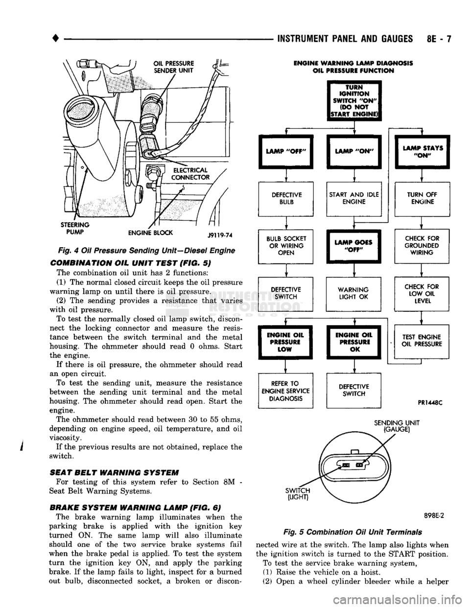
COMBINATION
OIL
UNIT
TEST
(FIG. 5)
The combination oil unit has 2 functions:
(1) The normal closed circuit keeps the oil pressure
warning lamp on until there is oil pressure. (2) The sending provides a resistance that varies
with oil pressure.
To test the normally closed oil lamp switch, discon
nect the locking connector and measure the resis
tance between the switch terminal and the metal
housing. The ohmmeter should read 0 ohms. Start
the engine.
If there is oil pressure, the ohmmeter should read
an open circuit. To test the sending unit, measure the resistance
between the sending unit terminal and the metal
housing. The ohmmeter should read open, Start the engine.
The ohmmeter should read between 30 to 55 ohms,
depending on engine speed, oil temperature, and oil
viscosity.
If the previous results are not obtained, replace the
switch.
SEAT
BELT
WARNING
SYSTEM
For testing of this system refer to Section 8M -
Seat Belt Warning Systems.
BRAKE
SYSTEM
WARNING
LAMP
(FIG. 6) The brake warning lamp illuminates when the
parking brake is applied with the ignition key
turned ON. The same lamp will also illuminate should one of the two service brake systems fail
when the brake pedal is applied. To test the system
turn the ignition key ON, and apply the parking
brake. If the lamp fails to light, inspect for a burned
out bulb, disconnected socket, a broken or discon-
ENGINE WARNING LAMP DIAGNOSIS
OIL PRESSURE
FUNCTION
TURN
IGNITION
SWITCH
"OH"
(DO NOT
ISTART ENGINE)! LAMP "OFF'
LAMP "ON"
DEFECTIVE BULB START AND IDLE
ENGINE
BULB SOCKET OR WIRING OPEN LAMP STAYS
"ON" TURN OFF
ENGINE LAMP GOES
"OFF" DEFECTIVE
SWITCH CHECK FOR
GROUNDED WIRING
WARNING
LIGHT
OK CHECK FOR
LOW OIL LEVEL
ENGINE OIL
PRISSURi
LOW
REFER TO
ENGINE SERVICE DIAGNOSIS ENGIM
PRES
0
IE OIL
1
SURE
1
,K I
DEFECTIVE SWITCH TEST ENGINE
OIL PRESSURE
PR1448C
SWITCH
(LIGHT)
SENDING
UNIT
(GAUGE)
898E-2
Fig.
5 Combination Oil Unit Terminals
nected wire at the switch. The lamp also lights when
the ignition switch is turned to the START position. To test the service brake warning system,
(1) Raise the vehicle on a hoist.
(2) Open a wheel cylinder bleeder while a helper
Page 444 of 1502
•
LAMPS
LAMPS
8L - 1
CONTENTS
page page
BULB
APPLICATION 11 EXTERIOR
LAMPS
SERVICE
PROCEDURES
... 3
EXTERIOR
LAMPS
1 INTERIOR
LAMPS
10
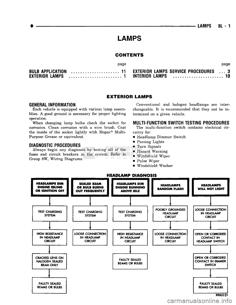
EXTERIOR LAMPS
GENERAL
INFORMATION Each vehicle is equipped with various lamp assem
blies.
A good ground is necessary for proper lighting operation. When changing lamp bulbs check the socket for
corrosion. Clean corrosion with a wire brush. Coat
the inside of the socket lightly with Mopar® Multi- Purpose Grease or equivalent.
DIAGNOSTIC
PROCEDURES
Always begin any diagnosis by testing all of the
fuses and circuit breakers in the system. Refer to Group 8W, Wiring Diagrams. Conventional and halogen headlamps are inter
changeable. It is recommended that they not be in
termixed on a given vehicle.
MULTI-FUNCTION
SWITCH TESTING
PROCEDURES
The multi-function switch contains electrical cir
cuitry for:
• Headlamp Dimmer Switch
• Passing Lights
• Turn Signals
• Hazard Warning • Windshield Wiper
• Pulse Wiper
• Windshield Washer
HEADLAMPS
HIM
ENGINE
IDLING
OR
IGNITION
OFF
TEST CHARGING
SYSTEM
HEADLAMP
DIAGNOSIS
SEALED
BEAM
OR
BULB
BURNS
OUT
FREQUENTLY
][
TEST CHARGING SYSTEM
HEADLAMPS
DIM
ENGINE
RUNNING
ABOVE
IDLE
][
TEST CHARGING SYSTEM
HEADLAMPS
RANDOM
FLASH
[
HEADLAMPS
WILL
NOT
LIGHT
POORLY GROUNDED HEADLAMP CIRCUIT
LOOSE
CONNECTION
IN HEADLAMP CIRCUIT
HIGH RESISTANCE IN HEADLAMP CIRCUIT
LOOSE
CONNECTION
IN HEADLAMP CIRCUIT HIGH RESISTANCE
IN HEADLAMP CIRCUIT
LOOSE
CONNECTION
IN HEADLAMP CIRCUIT OPEN OR CORRODED
CONTACT
IN
HEADLAMP SWITCH
CRACKED
LENS ON HALOGEN SEALED BEAM ONLY
FAULTY
SEALED
BEAMS
OR BULBS OPEN OR CORRODED
CONTACT IN DIMMER SWITCH
FAULTY
SEALED
BEAMS
OR BULBS
FAULTY
SEALED
BEAMS
OR BULBS
RR8LD21
Page 472 of 1502

-
CHIME/BUZZER WARNING SYSTEMS
8U - 1
CHIME/BUZZER
WARNING SYSTEMS
CONTENTS
page
DIAGNOSIS
GENERAL
INFORMATION
page
1
KEY-IN SWITCH REPLACEMENT
3
1
OPERATION
1
GENERAL
INFORMATION
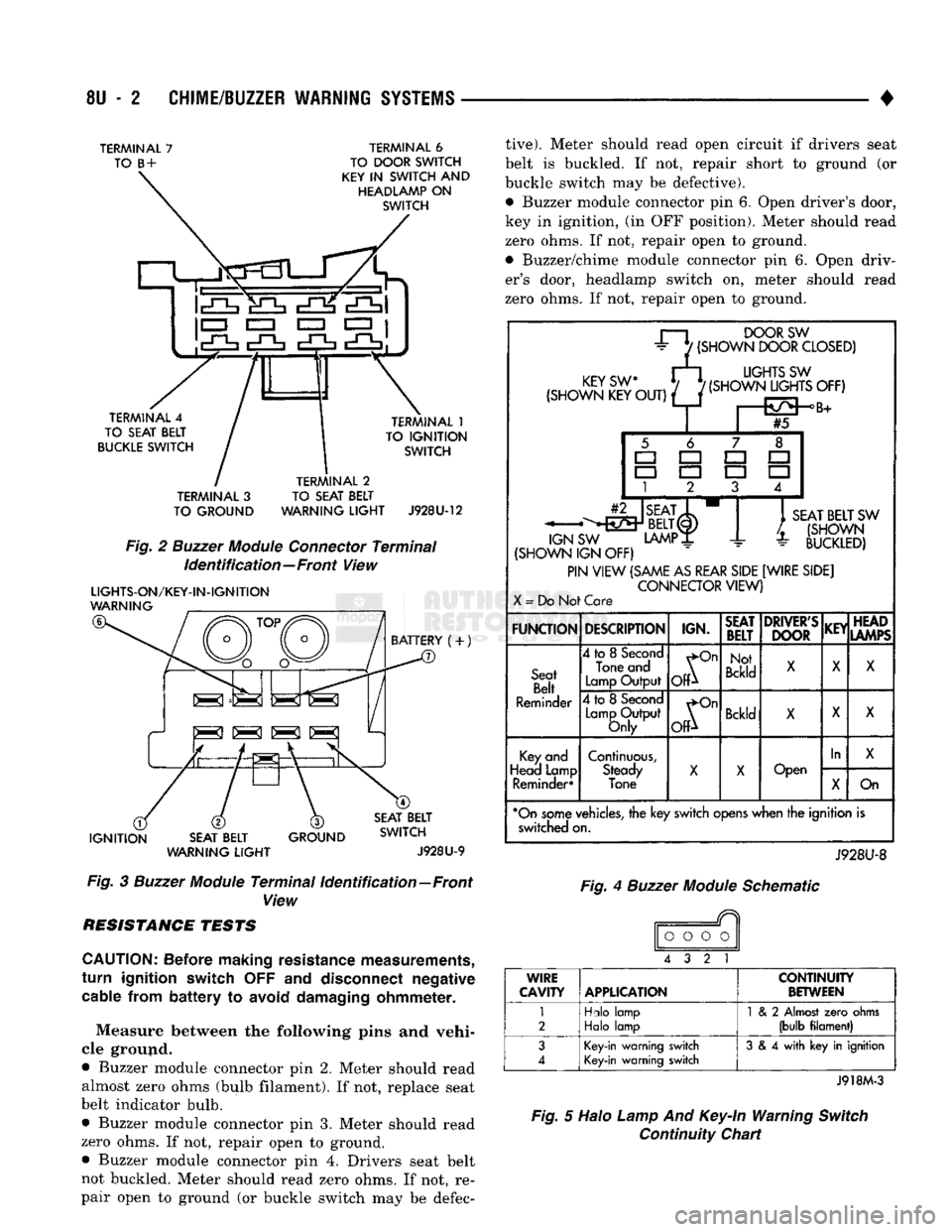
The buzzer module is located to the right of the
steering column (Fig. 1). The buzzer sounds an audi
ble warning tone in any of the following conditions: • Vehicle lights are ON when the driver's door is
opened.
• The key is in the ignition and the driver's door is
open. • The ignition is switched ON and the driver's seat
belt is not buckled. Buzzer will quit after 4 to 8 sec
onds.
In addition to the buzzer, a seat belt light in
dicator turns on as a reminder to fasten seat belt.
BUZZER
MODULE
INTERMITTENT
WIPE MODULE
Fig, 1 Buzzer Module Location
OPERATION
Battery voltage for module operation is supplied to
two pins. Battery voltage is present at pin 7 at all
times (Figs. 2 and 3). Pin 1 receives voltage when
the ignition switch is turned ON.
SEA T BELT WARNING To sound the seat belt warning, the module needs:
• battery voltage at the ignition switch input (Pin 1)
• a ground at the seat belt switch.
• a ground at Pin 3 to activate the timer. This occurs when the seat belt switch is closed be
cause the driver's seat belt is not buckled. The "fas
ten belt" light will also turn on along with the
warning sound. KEY IN IGNITION
To sound the "key in ignition" alarm, the module
needs:
• the ignition key warning switch must be closed
• the driver's door jamb switch must be closed. These conditions ground pin 6 of the module. These
switches are closed when the driver's door is open
and the key is in the ignition.
LIGHTS ON To sound the "lights on" warning, the module
needs:
• the headlamp switch must be closed
*> the driver's door jamb switch must be closed. These conditions ground pin 6 of the module. These
switches are closed when the driver's door is open
and the headlamp switch is on.
DIAGNOSIS
If the buzzer unit does not operate as described,
check the two fuses for pins 1 and 7 (Figs. 2, 3 and 4) and replace as required. If the fuses are not defec
tive,
perform the following tests to determine if the
problem is in the module or in the wiring. Using a flat blade screwdriver, release the locking plastic clip
while carefully pulling out the module. Plug in a known good module and check its operation. If the
problem is not corrected by replacing the module, re move the module and continue as follows:
VOLTAGE TESTS Ignition in run, measure between the following
pins and vehicle ground.
• Measure voltage at buzzer module connector pin 1.
Meter should read battery voltage. If not, repair open
to ignition switch.
Turn ignition off and remove key from igni
tion.
• Measure voltage at buzzer module connector pin 7.
Meter should read battery voltage. If not, repair open
to fuse. Battery voltage is present at Pin 7 at all
times regardless of key position.
Page 473 of 1502
8U
- 2
CHIME/BUZZER
WARNING SYSTEMS
•
TERMINAL
7
TO
B
+
TERMINAL
6
TO DOOR SWITCH
KEY
IN
SWITCH
AND
HEADLAMP
ON
SWITCH
!cO=f
Mi c£K
*£h
• CZ3
EZZ3
EZI 1
TERMINAL
4
TO SEAT BELT
BUCKLE SWITCH TERMINAL
1
TO
IGNITION
SWITCH
TERMINAL
3
TO GROUND TERMINAL
2
TO SEAT BELT
WARNING
LIGHT
J928U-12
Fig.
2
Buzzer
Module
Connector
Terminal
Identification—Front
View
LIGHTS-ON/KEY-IN-IGNITION
WARNING
BATTERY
(+)
IS SI S K|
IGNITION
SEAT BELT
WARNING
LIGHT
GROUND SEAT BELT
SWITCH
J928U-9
Fig.
3
Buzzer
Module
Terminal
Identification—Front
View RESISTANCE TESTS
CAUTION:
Before making resistance measurements,
turn
ignition switch
OFF and
disconnect negative cable from
battery
to
avoid damaging ohmmeter.
Measure between the following pins and vehi
cle ground.
• Buzzer module connector pin 2. Meter should read almost zero ohms (bulb filament). If not, replace seat
belt indicator bulb.
• Buzzer module connector pin 3. Meter should read
zero ohms. If not, repair open to ground. • Buzzer module connector pin 4. Drivers seat belt
not buckled. Meter should read zero ohms. If not, re
pair open to ground (or buckle switch may be defec
tive).
Meter should read open circuit if drivers seat
belt is buckled. If not, repair short to ground (or buckle switch may be defective).
• Buzzer module connector pin 6. Open driver's door,
key in ignition, (in OFF position). Meter should read
zero ohms. If not, repair open to ground.
• Buzzer/chime module connector pin 6. Open driv
er's door, headlamp switch on, meter should read
zero ohms. If not, repair open to ground.
r—i
DOORSW
±
7
(SHOWN
DOOR
CLOSED)
rFY<;w M
UGHTS
SW
(SHOWN
KEW/
f(SHOWN^JGHTS
OFF)
#5 -^•^Y
BELT(I)
SW
LAMP
JL
SEAT
BELT
SW
/.
(SHOWN
-
BUCKLED)
IGN
SW
(SHOWN
IGN OFF)
PIN
VIEW
(SAME
AS
REAR
SIDE
[WIRE
SIDE]
CONNECTOR
VIEW)
X
=
Do Not Care
FUNCTION
DESCRIPTION
IGN.
SEAT
BELT
DRIVER'S
DOOR
KEY
HEAD
LAMPS
Seat
Belt
Reminder
4
to
8
Second
Tone and
Lamp
Output
^On
OP
Not
Bckld
X
X
X
Seat
Belt
Reminder
4
to
8
Second
Lamp
Output
Only
^On
OfP
Bckld
X X
X
Key
and
Head Lamp Reminder*
Continuous,
Steady
Tone
X
X
Open
In
X
Key
and
Head Lamp Reminder*
Continuous,
Steady
Tone
X
X
Open
X
On
*On
some
vehicles,
the key
switch
opens
when the ignition is switched on.
J928U-8
Fig.
4
Buzzer
Module
Schematic
o
o o o
4 3 2 1
WIRE
CAVITY APPLICATION
CONTINUITY
BETWEEN
1
2
Hdo
lamp
Halo
lamp
1
& 2
Almost
zero
ohms
(bulb
filament)
3
4
Key-in
warning switch
Key-in
warning switch
3
& 4
with
key in ignition
J918M-3
Fig.
5 Halo
Lamp
And
Key-In
Warning
Switch
Continuity Chart