1993 DODGE TRUCK service
[x] Cancel search: servicePage 1 of 1502

19 9 3
SERVICE
MANUAL
D&
W150-350
RAMCHARGER
REAR
WHEEL DRIVE TRUCK
Page 2 of 1502
CHRYSLER
CORPORATION
SERVICE
MANUAL
1993
DODGE TRUCKS
To order the special service tools used and
illustrated, please refer to the instructions on inside back cover.
CHRYSLER
W
CORPORATION
NO PART OF THIS PUBLICATION MAY BE
REPRODUCED, STORED IN A RETRIEVAL SYSTEM, OR TRANSMITTED, IN ANY FORM
OR BY ANY MEANS, ELECTRONIC, ME
CHANICAL, PHOTOCOPYING, RECORDING,
OR OTHERWISE, WITHOUT THE PRIOR
WRITTEN PERMISSION OF CHRYSLER CORPORATION.
Chrysler
Corporation
reserves
the
right
to make
changes
in
design
or to make
additions to or improvements in its products
without
imposing any obliga
tions upon
itself
to
install
them
on its products previously manufactured.
Litho
in
U.S.A.
Copyright ©
1992
Chrysler Corporation
15M0992
Page 3 of 1502

FOREWORD
The information contained in this service manual has been prepared for the professional automotive tech
nician involved in daily repair operations. This manual does not cover theory of operation, which is addressed in service training material. Information describing the operation and use of standard and optional equipment
is included in the Owner's Manual provided with the vehicle.
Information in this manual is divided into groups. These groups contain general information, diagnosis,
testing, adjustments, removal, installation, disassembly, and assembly procedures for the components.
The Component and System Index of this manual identifies the correct group for the component or system
to be serviced. In addition, a Service Manual Comment form is included at the rear of this manual. Use the form to provide Chrysler Corporation with your comments and suggestions.
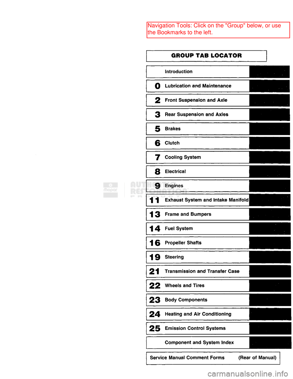
To assist in locating a group title page, use the Group Tab Locator on the following page. The solid bar
after the group title is aligned to a solid tab on the first page of each group. The first page of the group has
a contents section that lists major topics within the group.
Tightening torques are provided as a specific value throughout this manual. This value represents the
midpoint of the acceptable engineering torque range for a given fastener application. These torque values are
intended for use in service assembly and installation procedures using the correct OEM fasteners. When re
placing fasteners, always use the same type (part number) fastener as removed.
Chrysler Corporation reserves the right to change testing procedures, specifications, diagnosis, repair
methods, or vehicle wiring at any time without prior notice or incurring obligation.
NOTE: The acronyms, terminology and nomenclature used to identify emissions related components in
this manual may have changed from prior publications. These new terms are in compliance with S.A.E.
recommended practice J1930. This terminology standard (J1930) is required to comply with the 1993 California Air Research Board (CARB) requirements.
Page 4 of 1502
GROUP TAB LOCATOR
Introduction
0
Lubrication
and
Maintenance
2
Front Suspension
and
Axle
3
Rear Suspension
and
Axles
5
Brakes
6
Clutch
7
Cooling System
8
Electrical
9
Engines
11
Exhaust System
and
Intake
Manifold
13
Frame
and Bumpers
14
Fuel
System
16
Propeller Shafts
19
Steering
21
Transmission
and
Transfer Case
22
Wheels and Tires
23
Body Components
24
Heating
and Air
Conditioning
25
Emission Control Systems Component and System Index
Service Manual Comment Forms (Rear
of
Manual)
Page 6 of 1502
INTRODUCTION
INTRODUCTION
DESIGNATIONS,
LABELS/PLATES/DECALS,
CODES
AND DIMENSIONS/WEIGHTS .
CONTENTS
page
MEASUREMENT
AND TORQUE
... 1 SPECIFICATIONS
page
. 11
DESIGNATIONS, LABELS/PLATES/DECALS, CODES
AND
DIMENSIONS/WEIGHTS
INDEX
page
Engine
and
Transmission/Transfer
Case
Identification
2
Engine/Transmission/GVWR
4
Equipment
Identification
Plate
3
International
Vehicle Control
and
Display
Symbols
10
Major Component
Identification 3
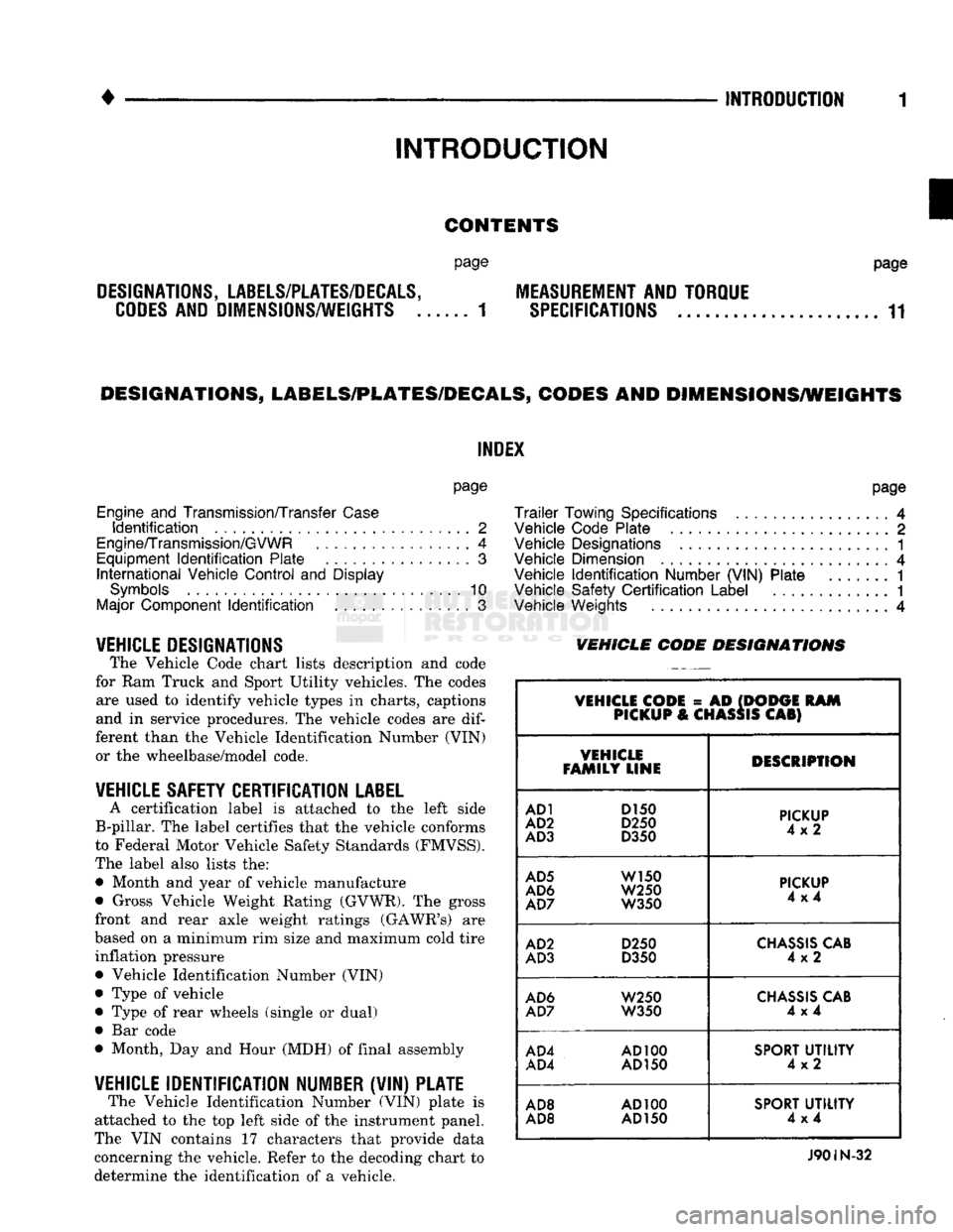
VEHICLE DESIGNATIONS The Vehicle Code chart lists description and code
for Ram Truck and Sport Utility vehicles. The codes are used to identify vehicle types in charts, captions
and in service procedures. The vehicle codes are
dif
ferent than the Vehicle Identification Number (VIN) or the wheelbase/model code.
VEHICLE SAFETY CERTIFICATION
LABEL
A certification label is attached to the left side
B-pillar. The label certifies that the vehicle conforms
to Federal Motor Vehicle Safety Standards (FMVSS).
The label also lists the: • Month and year of vehicle manufacture
• Gross Vehicle Weight Rating (GVWR). The gross
front and rear axle weight ratings (GAWR's) are
based on a minimum rim size and maximum cold tire inflation pressure Vehicle Identification Number (VIN)
Type of vehicle
Type of rear wheels (single or dual) Bar code
Month, Day and Hour (MDH) of final assembly
VEHICLE IDENTIFICATION NUMBER (VIN) PLATE The Vehicle Identification Number (VIN) plate is
attached to the top left side of the instrument panel.
The VIN contains 17 characters that provide data
concerning the vehicle. Refer to the decoding chart to
determine the identification of a vehicle.
page
Trailer
Towing Specifications
4
Vehicle Code Plate
2
Vehicle Designations
1
Vehicle Dimension
4
Vehicle
Identification
Number (VIN) Plate
1
Vehicle Safety
Certification
Label
............. 1
Vehicle Weights
4
VEHICLE CODE
DESIGNATIONS
VEHICLE CODE
= AD
(DODGE
RAM
PICKUP
&
CHASSIS
CAB)
VEHICLE
FAMILY LINE DESCRIPTION
AD1
D150
AD2
D250
AD3
D350
PICKUP
4x2
AD5
W150
AD6
W250
AD7
W350
PICKUP
4x4
AD2
D250
AD3
D350
CHASSIS
CAB
4x2
AD6
W250
AD7
W350
CHASSIS
CAB
4x4
AD4
AD100
AD4
AD150
SPORT
UTILITY
4x2
AD8
AD100
AD8 AD
150
SPORT
UTILITY
4x4
J90IN-32
Page 16 of 1502
•
INTRODUCTION
11
MEASUREMENT
AND
TORQUE SPECIFICATIONS
INDEX
page
Metric
and
English/SAE
Conversion
11
Specification
Notations
11
SPECIFICATION NOTATIONS
WARNING:
THE USE OF
INCORRECT
ATTACHING
HARDWARE
CAN
RESULT
IN
COMPONENT
DAM
AGE
AND/OR
PERSONAL
INJURY.
It is important to retain the original attaching
hardware for assembly of the components. If the at
taching hardware is not reusable, hardware with
equivalent specifications must be used.
METRIC
AND
ENGLISH/SAE
CONVERSION
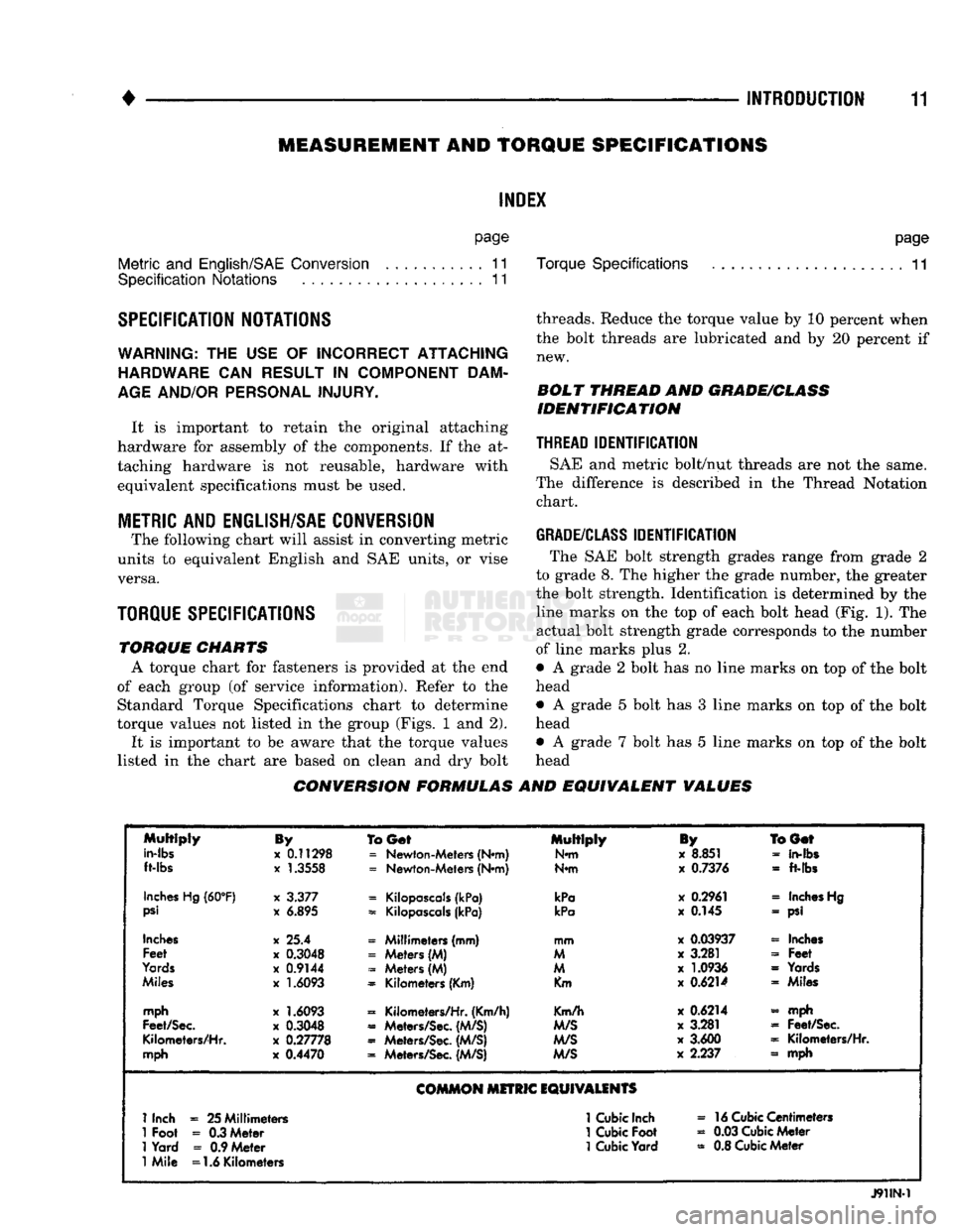
The following chart will assist in converting metric
units to equivalent English and SAE units, or vise versa.
TORQUE SPECIFICATIONS
TORQUE
CHARTS
A torque chart for fasteners is provided at the end
of each group (of service information). Refer to the Standard Torque Specifications chart to determine
torque values not listed in the group (Figs. 1 and 2).
It is important to be aware that the torque values
listed in the chart are based on clean and dry bolt
page
Torque Specifications
11
threads. Reduce the torque value by 10 percent when the bolt threads are lubricated and by 20 percent if new.
BOLT
THREAD
AND
GRADE/CLASS
IDENTIFICATION
THREAD
IDENTIFICATION
SAE and metric bolt/nut threads are not the same.
The difference is described in the Thread Notation chart.
GRADE/CLASS
IDENTIFICATION
The SAE bolt strength grades range from grade 2
to grade 8. The higher the grade number, the greater
the bolt strength. Identification is determined by the line marks on the top of each bolt head (Fig. 1). The
actual bolt strength grade corresponds to the number
of line marks plus 2.
• A grade 2 bolt has no line marks on top of the bolt
head
• A grade 5 bolt has 3 line marks on top of the bolt
head • A grade 7 bolt has 5 line marks on top of the bolt
head
CONVERSION FORMULAS
AND
EQUIVALENT
VALUES
Multiply
in-lbs
ft-lbs
By
x
0.11298
x
1.3558
To
Get
=
Newton-Meters (N*m)
=
Newton-Meters (N*m) Multiply
N*m
iy
x
8.851
x
0.7376
BGef
-
in-fbs
-
ft-lbs
Inches
Hg
(60°F)
psi
x
3.377
x
6.895
=
Kilopascals
(kPa)
=
Kilopascals
(kPa)
kPa
kPa
x
0.2961
x
0.145
«
Inches
Hg
- psi
Inches
Feet
Yards
Miles
x 25.4
x
0.3048
x
0.9144
x
1.6093
« Millimeters (mm)
=
Meters (M)
-
Meters (M)
=
Kilometers (Km) mm
M
M
Km
x
0.03937
x
3.281
x
1.0936
x
0.6214
« Inches
-
Feet
=
Yards « Miles
mph
Feet/Sec.
Kilometers/Hr.
mph
x
1.6093
x
0.3048
x
0.27778
x
0.4470
=
Kilometers/Hr. (Km/h)
«
Meters/Sec.
(M/S)
«
Meters/Sec.
(M/S)
=
Meters/Sec.
(M/S)
Km/h
M/S
M/S
M/S
x
0.6214
x
3.281
x
3.600
x
2.237 - mph
=
Feet/Sec.
=
Kilometers/Hr.
» mph
COMMON
MITRIC
EQUIVALENTS
1
Inch
=
25 Millimeters
1
Cubic
Inch
»
16
Cubic
Centimeters
1
Foot
-
0.3 Meter
1
Cubic
Foot
«
0.03
Cubic
Meter
1
Yard
=
0.9 Meter
1
Cubic
Yard
=
0.8
Cubic
Meter
1
Mile =1.6 Kilometers
J91IN-1
Page 20 of 1502
•
• —
LUiRICATlON
AND
MAINTENANCE
0 - 1
CONTENTS
page
page
CHASSIS
AND
BODY
28
ENGINE MAINTENANCE
14
DRIVETRAIN
.,,, 22
GENERAL INFORMATION
1
GENERAL
INFORMATION INDEl
page
Classification
of
Lubricants
. 3
Components
Requiring
No
Lubrication
4
Fuel Requirements
. 2
Introduction
1
Lubrication
and
Replacement Parts Recommendation
3
page
Routine Maintenance
2
Starting
Assistance (Jump Starting)
9
Vehicle
Lifting
Recommendations
............ 10
Vehicle Noise
Control
2
Vehicle Towing Recommendations
11
INTRODUCTION
Lubrication and maintenance is divided into re
quired and recommended service tasks. The required service tasks must be completed to verify the emis
sion controls function correctly. The recommended
service tasks should be completed to maintain safety
and durability. This information will assist the service personnel
in providing maximum protection for each owner's
vehicle. Conditions can vary with individual driving habits.
It is necessary to schedule maintenance as a time in
terval as well as a distance interval. It is the owner's responsibility to determine the ap
plicable driving condition. Also to have the vehicle serviced according to the maintenance schedule, and
to pay for the necessary parts and labor. Vehicles with a Gross Vehicle Weight Rating
(GVWR) of 3 855 kg (8,500 lbs.) or less must conform
to light duty emission standards. Vehicles with a Gross Vehicle Weight Rating (GVWR) of 3 856 kg
(8,501 lbs.) or more must conform to heavy duty
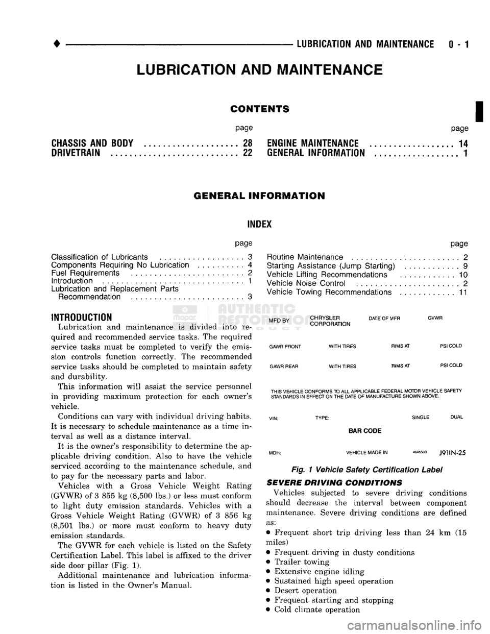
emission standards. The GVWR for each vehicle is listed on the Safety
Certification Label. This label is affixed to the driver
side door pillar (Fig. 1).
Additional maintenance and lubrication informa
tion is listed in the Owner's Manual.
Mm
rv
CHRYSLER
DATE
OF MFR
MFD BY CORPORATION
GVWR
GAWR FRONT
GAWR REAR
WITH
TIRES
WITH
TIRES
RIMS
AT
RIMS
AT
PSI
COLD
PSI
COLD THIS VEHICLE CONFORMS
TO
ALL APPLICABLE FEDERAL MOTOR VEHICLE SAFETY
STANDARDS
IN
EFFECT ON
THE
DATE
OF
MANUFACTURE SHOWN ABOVE.
SINGLE
DUAL
BAR
CODE
VEHICLE MADE
IN
4648503
J9UN-25
Fig. 1 Vehicle Safety
Certification
Label
SEVERE DRIVING
CONDITIONS
Vehicles subjected to severe driving conditions
should decrease the interval between component
maintenance. Severe driving conditions are defined
as:
• Frequent short trip driving less than 24 km (15
miles)
• Frequent driving in dusty conditions
• Trailer towing
• Extensive engine idling
• Sustained high speed operation
• Desert operation
• Frequent starting and stopping
• Cold climate operation
LUBRICATION
AND
MAINTENANCE
Page 21 of 1502
0 - 2
LUBRICATION
AND
MAINTENANCE
• Commercial service
When a vehicle is continuously subjected to severe
driving conditions, lubricate:
• Body components
• All the driveline coupling joints
• Steering linkage More often than normal driving conditions
DUSTY
AREAS
With this type of severe driving condition, special
care should be given to the:
• Engine air cleaner filter
• PCV filter
• Crankcase ventilation system
• Brake booster control valve air filter. Verify that the filters and the associated compo
nents are clean. Also verify that they are functioning
effectively. This will minimize the amount of abra sive particles that enter the engine.
OFF-ROAD
(4WD)
OPERATION
After off-road (4WD) operation, inspect the under
side of the vehicle. Inspect the:
• Tires
• Body structure
• Steering components
• Suspension components • Exhaust system
• Threaded fasteners
HARSH
SURFACE ENVIRONMENTS
After extended operation in harsh environments,
the brake drums, brake linings, and rear wheel bear ings should be inspected and cleaned. This will pre
vent wear and erratic brake action.
ROUTINE MAINTENANCE
The following routine maintenance is recommended
on a monthly basis: TIRES—Inspect the tires for unusual wear/damage.
Determine if the inflation pressure is adequate for
the vehicle load. BATTERY—Inspect and clean the terminals.
Tighten the terminals if necessary. FLUIDS—Determine if the component fluid levels
are acceptable. Add fluid, if necessary. LIGHTS/ELECTRICAL—Test all the electrical sys
tems in the vehicle for proper operation. It is also recommended that the engine oil and the
washer fluid level be determined at each fuel fill-up.
VEHICLE
NOISE CONTROL
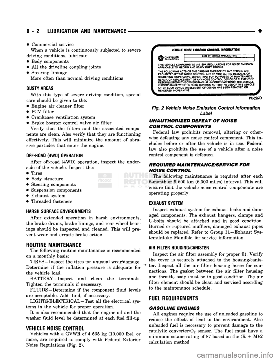
Vehicles with a GVWR of 4 535 kg (10,000 lbs), or
more, are required to comply with Federal Exterior Noise Regulations (Fig. 2).
VEHICLE
NOISE
EMISSION
CONTROL INFORMATION
DATE
OF
VEHICLE
MANUFACTURE
THIS
VEHICLE CONFORMS
TO
U.S. EPA REGULATIONS FOR NOISE EMISSION
APPLICABLE
TO
MEDIUM
AND HEAVY
DUTY
TRUCKS. THE
FOLLOWING
ACTS OR THE CAUSING THEREOF BY ANY PERSON ARE PROHIBITED BY THE NOISE CONTROL ACT
OF 1972. (A) THE
REMOVAL
OR
RENDERING
INOPERATIVE, OTHER
THAN
FOR
PURPOSES
OF
MAINTENANCE,
REPAIR.
OR REPLACEMENT, OF ANY NOISE CONTROL DEVICE OR ELEMENT OF
DESIGN
(LISTED
IN
THE
OWNERS
MANUAL)
INCORPORATED
INTO
THIS
VEHICLE
IN COMPLIANCE
WITH
THE NOISE CONTROL
ACT:
(B) THE
USE
OF
THIS
VEHICLE
AFTER SUCH DEVICE
OR
ELEMENT
OF
DESIGN HAS BEEN REMOVED
OR
RENDERED
INOPERATIVE.
PU626D
Fig.
2 Vehicle
Noise
Emission
Control Information
Label
UNAUTHORIZED
DEFEAT
OF
NOISE
CONTROL COMPONENTS
Federal law prohibits removal, altering or other
wise defeating any noise control component. This in
cludes before or after the vehicle is in use. Federal
law also prohibits the use of a vehicle after a noise
control component is defeated.
REQUIRED MAINTENANCE/SERVICE
FOR
NOISE
CONTROL
The following maintenance is required after each
6-month or 9 600 km (6,000 miles) interval. This will
ensure that the vehicle noise control components are
operating properly.
EXHAUST SYSTEM
Inspect exhaust system for exhaust leaks and dam
aged components. The exhaust hangers, clamps and
U-bolts should be attached and in good condition.
Burned or ruptured mufflers, damaged exhaust pipes should be replaced. Refer to Group 11—Exhaust Sys
tem/Intake Manifold for service information.
AIR
FILTER
HOUSING/CANISTER
Inspect the air filter assembly for proper fit. Verify
the cover is securely attached to the housing/canis
ter. Inspect all the air filter housing hoses for con nections. The gasket between the air filter housing and throttle body must be in good condition. The air
filter element should be clean and serviced according
to the maintenance schedule.
FUEL
REQUIREMENTS
GASOLINE
ENGINES
All engines require the use of unleaded gasoline to
reduce the effects of lead to the environment. Also unleaded fuel is necessary to prevent damage to the
catalytic converter/02 sensor. The fuel must have a
minimum octane rating of 87 based on the (R + M)/2
calculation method.