1993 DODGE TRUCK service
[x] Cancel search: servicePage 1486 of 1502
•
EMISSION
CONTROL
SYSTEMS
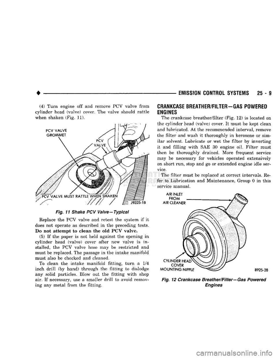
25 - 9 (4) Turn engine off and remove PCV valve from
cylinder head (valve) cover. The valve should rattle
when shaken (Fig. 11).
Fig. 11
Shake
PCV Valve-Typical
Replace the PCV valve and retest the system if it
does not operate as described in the preceding tests.
Do not attempt to clean the old PCV valve.
(5) If the paper is not held against the opening in
cylinder head (valve) cover after new valve is in stalled, the PCV valve hose may be restricted and
must be replaced. The passage in the intake manifold
must also be checked and cleaned. To clean the intake manifold fitting, turn a 1/4
inch drill (by hand) through the fitting to dislodge
any solid particles. Blow out the fitting with shop air. If necessary, use a smaller drill to avoid remov
ing any metal from the fitting.
CRANKCASE
BREATHER/FILTER-GAS POWERED
ENGINES
The crankcase breather/filter (Fig. 12) is located on
the cylinder head (valve) cover. It must be kept clean and lubricated. At the recommended interval, remove
the filter and wash it thoroughly in kerosene or sim ilar solvent. Lubricate or wet the filter by inverting
it and filling with SAE 30 engine oil. Filter must
then be thoroughly drained. More frequent service
may be necessary for vehicles operated extensively on short run, stop and go or extended engine idle ser
vice.
The filter must be replaced at correct intervals. Re
fer to Lubrication and Maintenance, Group 0 in this service manual. 8925-28
Fig. 12 Crankcase Breather/Filter—Gas Powered
Engines
Page 1488 of 1502
•
EMISSION
CONTROL
SYSTEMS
25 - 11 • The electrical solenoid portion of the EET is not
energized.
• The engine back pressure entering the EGR valve
inlet is strong enough to close the transducer bleed
valve.
If back pressure is not strong enough to close the
transducer bleed valve, the transducer will bleed off the vacuum preventing EGR operation.
When the electrical solenoid portion of the EET is
de-energized by the powertrain control module (PCM), vacuum flows to the transducer. The trans
ducer is connected to the engine exhaust system by a small hose that connects to the base of the EGR
valve.
The vacuum section of the transducer is controlled
by exhaust system back pressure. When back pres sure is high enough it will close a bleed valve in the
transducer allowing vacuum to actuate the EGR
valve. If back pressure does not close the bleed valve,
vacuum will be bled off.
For more information, refer to Group 14, Fuel Sys
tems.
Refer to the Component Removal/Installation sec
tion of this group for EGR valve replacement proce
dures.
EGR SYSTEM ON-BOARD DIAGNOSTICS
(CALIFORNIA VEHICLES
ONLY)
The powertrain control module (PCM) performs an
On-Board Diagnostic (OBD) check of the EGR system
on all California vehicles. The diagnostic system uses
the electric EGR transducer (EET) for the system
tests.
The OBD check activates only during selected en
gine/driving conditions. When the conditions are met,
the PCM energizes the EET solenoid to disable the EGR. The PCM checks for a change in the oxygen sensor signal. If the air-fuel mixture goes lean, the
PCM will attempt to enrichen the mixture. The PCM
registers a diagnostic trouble code (DTC) if the EGR system has failed or degraded. After registering a
DTC,
the PCM turns the malfunction indicator
lamp (MIL) on. (The malfunction indicator lamp was formerly referred to as the check engine lamp). The
malfunction indicator lamp indicates the need for im
mediate service.
If a malfunction is indicated by the malfunction in
dicator lamp and a DTC for the EGR system was set,
check for proper operation of EGR system. Use the
following: System Test, EGR Gas Flow Test and EGR
Diagnosis Chart.
If the EGR system tests properly, check the system
using the DRB II scan tool. For use of the DRB II,
refer to the appropriate Powertrain Diagnostics Pro cedure service manual. EGR SYSTEM SERVICE
A malfunctioning EGR system can cause engine
spark knock, sags or hesitation, rough idle, engine
stalling and poor driveability. To be sure of proper
operation of the EGR system, inspect all passages for
blockage. Check moving parts for binding. Inspect
the complete system for leaks. Replace system com ponents or hoses that are leaking.
Inspect all hose connections between throttle body,
intake manifold, EGR valve and EGR purge solenoid.
Replace any vacuum harness components that are
leaking or damaged. Refer to EGR Control System Test and EGR Gas
Flow Test to check EGR System operation.
EGR GAS FLOW TEST (1) Disconnect hose from EGR valve and connect a
hand vacuum pump to EGR valve nipple. Apply a
minimum of 12 inches vacuum the valve.
(2) The engine should now idle roughly or stall. If
this occurs, the valve is performing correctly. Proceed
to Electric EGR Transducer Test.
(3) If the engine idle speed did not change, remove
the EGR valve and inspect the valve and the exhaust passage in the manifold for blockage. Repair as nec
essary. If blockage is not present, replace the EGR
valve.
ELECTRIC EGR TRANSDUCER (EET)
TESTING ELECTRIC SOLENOID PORTION OF TRANSDUCER
(1) Bring the engine to normal operating tempera
ture.
Operate at idle speed. Test the EET as follows: (2) Check vacuum at EET vacuum source. Discon
nect the hose and attach a vacuum gauge to it.
(3) Vacuum should be a minimum of 15 inches:
• If vacuum is low, check the line for kinks, twists
or a loose connection at vacuum connector or intake
manifold.
• If vacuum is correct, remove gauge. Connect the
vacuum line and proceed to next step. (4) Check EET operation using the appropriate
Powertrain Diagnostic Procedures service manual.
Refer to this manual for use of the DRB II scan tool and repair EET as necessary.
TESTING VACUUM PORTION
OF
TRANSDUCER
(1) Disconnect the EET vacuum lines, back pres
sure line and electrical connector. Remove trans
ducer.
(2) Plug the EET EGR valve port.
(3) Apply 1-2 pounds air pressure to exhaust back
pressure port. Air pressure can be supplied with a
hand operated air pump or compressed air (regulated
to correct psi).
(4) Apply a minimum of 12 inches of vacuum to
vacuum supply port.
Replace the EET if it will not hold vacuum.
Page 1490 of 1502
EMISSION
CONTROL
SYSTEMS
25 - 13
For electrical tests
of the EET and its
circuitry,
re
fer
to the
appropriate Powertrain Diagnostic Proce dures service manual
for use of the DRB II
scan tool.
Refer
to the
Component Removal/Installation sec
tion
of
this group
for EET
replacement procedures.
OXYGEN
(02)
SENSOR
For description, operation, diagnosis
and
removal/
installation procedures
of the 02
sensor, refer
to
Group
14,
Fuel Systems.
AIR
INLET—5.9L
DIESEL
ENGINE
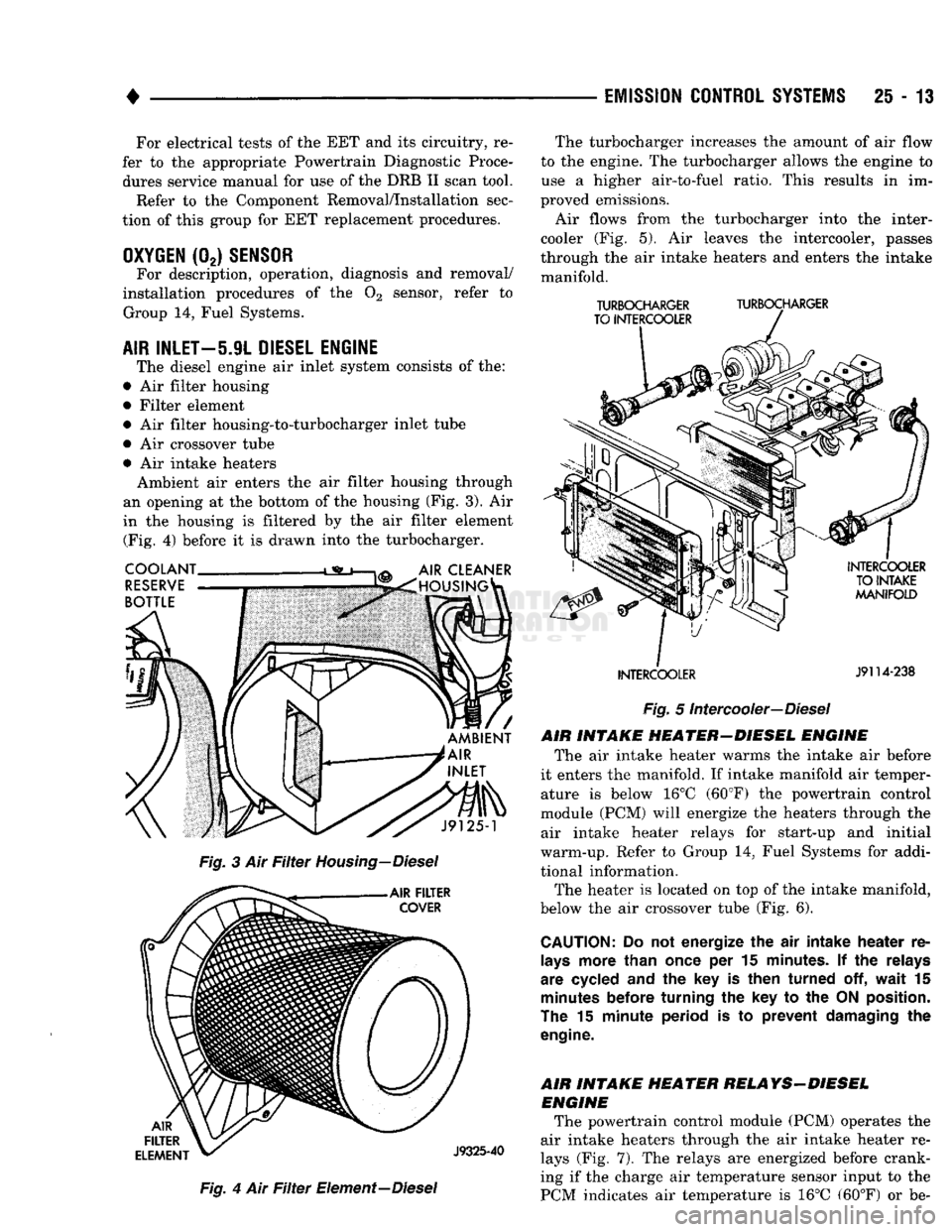
The diesel engine
air
inlet system consists
of the:
•
Air
filter housing
• Filter element •
Air
filter housing-to-turbocharger inlet tube
•
Air
crossover tube •
Air
intake heaters Ambient
air
enters
the air
filter housing through
an opening
at the
bottom
of the
housing
(Fig. 3). Air
in
the
housing
is
filtered
by the air
filter element (Fig.
4)
before
it is
drawn into
the
turbocharger.
Fig.
4 Air Filter
Element—Diesel The turbocharger increases
the
amount
of air
flow
to
the
engine.
The
turbocharger allows
the
engine
to
use
a
higher air-to-fuel ratio. This results
in im
proved emissions.
Air flows from
the
turbocharger into
the
inter-
cooler
(Fig. 5). Air
leaves
the
intercooler, passes
through
the air
intake heaters
and
enters
the
intake manifold.
TURBOCHARGER
TURBOCHARGER
TO INTERCOOLER
INTERCOOLER
J9114-238
Fig.
5
Intercooler—Diesel
AIR INTAKE HEATER-DIESEL ENGINE The
air
intake heater warms
the
intake
air
before
it enters
the
manifold.
If
intake manifold
air
temper ature
is
below
16°C
(60°F)
the
powertrain control
module
(PCM)
will energize
the
heaters through
the
air intake heater relays
for
start-up
and
initial
warm-up. Refer
to
Group
14,
Fuel Systems
for
addi
tional information. The heater
is
located
on top of the
intake manifold,
below
the air
crossover tube
(Fig. 6).
CAUTION:
Do not
energize
the air
intake heater
re
lays
more than once
per 15
minutes.
If the
relays
are cycled
and the key is
then turned
off,
wait
15
minutes
before turning
the key to the
ON
position.
The
15
minute period
is to
prevent damaging
the
engine.
AIR INTAKE HEATER RELAYS-DIESEL ENGINE The powertrain control module
(PCM)
operates
the
air intake heaters through
the air
intake heater
re
lays
(Fig. 7). The
relays
are
energized before crank
ing
if the
charge
air
temperature sensor input
to the
PCM indicates
air
temperature
is 16°C
(60°F)
or be-
Page 1496 of 1502
•
EMISSION
CONTROL SYSTEMS
25 - 19
EGR
VALVE
REMOVAL
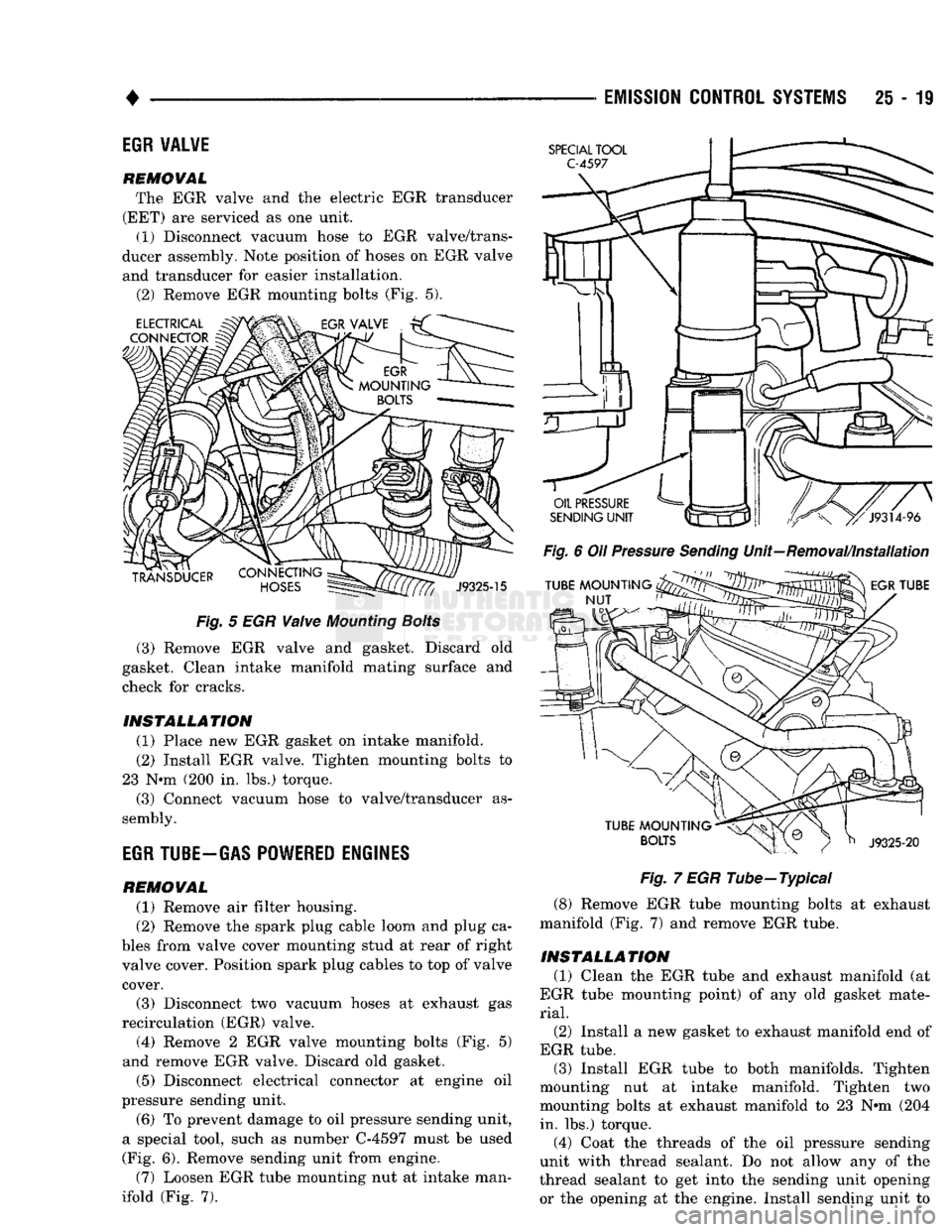
The EGR valve and the electric EGR transducer
(EET) are serviced as one unit.
(1) Disconnect vacuum hose to EGR valve/trans
ducer assembly. Note position of hoses on EGR valve
and transducer for easier installation.
(2) Remove EGR mounting bolts (Fig. 5).
Fig.
5 EGR
Valve
Mounting
Bolts
(3) Remove EGR valve and gasket. Discard old
gasket. Clean intake manifold mating surface and
check for cracks.
INSTALLATION
(1) Place new EGR gasket on intake manifold. (2) Install EGR valve. Tighten mounting bolts to
23 N*m (200 in. lbs.) torque. (3) Connect vacuum hose to valve/transducer as
sembly.
EGR
TUBE-GAS POWERED ENGINES
REMOVAL
(1) Remove air filter housing.
(2) Remove the spark plug cable loom and plug ca
bles from valve cover mounting stud at rear of right
valve cover. Position spark plug cables to top of valve cover.
(3) Disconnect two vacuum hoses at exhaust gas
recirculation (EGR) valve. (4) Remove 2 EGR valve mounting bolts (Fig. 5)
and remove EGR valve. Discard old gasket.
(5) Disconnect electrical connector at engine oil
pressure sending unit.
(6) To prevent damage to oil pressure sending unit,
a special tool, such as number C-4597 must be used
(Fig. 6). Remove sending unit from engine.
(7) Loosen EGR tube mounting nut at intake man
ifold (Fig. 7).
Fig.
6 Oil
Pressure
Sending
Unit—Removal/Installation
Fig.
7 EGR Tube—Typical
(8) Remove EGR tube mounting bolts at exhaust
manifold (Fig. 7) and remove EGR tube.
INSTALLATION
(1) Clean the EGR tube and exhaust manifold (at
EGR tube mounting point) of any old gasket mate
rial.
(2)
Install a new gasket to exhaust manifold end of
EGR tube. (3) Install EGR tube to both manifolds. Tighten
mounting nut at intake manifold. Tighten two
mounting bolts at exhaust manifold to 23 N»m (204 in. lbs.) torque.
(4) Coat the threads of the oil pressure sending
unit with thread sealant. Do not allow any of the
thread sealant to get into the sending unit opening
or the opening at the engine. Install sending unit to
Page 1497 of 1502
25 - 20
EMISSION CONTROL SYSTEMS
• engine and tighten to 14 N*m (130 in. lbs.) torque.
Install electrical connector to sending unit.
(5) Clean the intake manifold and EGR valve of
any old gasket material.
(6) Install a new EGR valve gasket to intake man
ifold. (7) Install EGR valve to intake manifold. Tighten
two mounting bolts to 23 N*m (200 in. lbs.) torque.
(8) Install vacuum lines to EGR valve.
(9) Install spark plug cable loom and plug cables to
valve cover mounting stud.
(10) Install air filter housing.
ELECTRIC EGR TRANSDUCER
(EET) The EGR valve and the EET are serviced as one
unit. Also refer to EGR valve removal/installation.
REMOVAL
(1) Remove air filter housing.
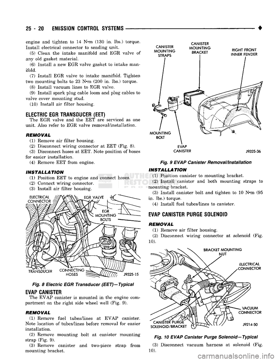
(2) Disconnect wiring connector at EET (Fig. 8). (3) Disconnect hoses at EET. Note position of hoses
for easier installation.
(4) Remove EET from engine.
INSTALLATION (1) Position EET to engine and connect hoses.
(2) Connect wiring connector. (3) Install air filter housing.
ELECTRICAL
CONNECTOR
TRANSDUCER
J9325-15
Fig.
8 Electric EGR Transducer (EET)—Typical
EVAP
CANISTER
The EVAP canister is mounted in the engine com
partment on the right side wheel well (Fig. 9).
REMOVAL
(1) Remove fuel tubes/lines at EVAP canister.
Note location of tubes/lines before removal for easier
installation. (2) Remove mounting bolt at canister mounting
strap (Fig. 9).
(3) Remove canister and two-piece strap from
mounting bracket.
CANISTER
MOUNTING
STRAPS
CANISTER
MOUNTING
BRACKET RIGHT FRONT
INNER FENDER
MOUNTING
BOLT
EVAP
CANISTER
J9325-36
Fig.
9
EVAP
Canister Removal/Installation INSTALLATION
(1) Position canister to mounting bracket.
(2) Install canister and both mounting straps to
mounting bracket.
(3) Install canister bolt and tighten to 10 N*m (95
in. lbs.) torque.
(4) Install fuel tubes/lines to canister.
EVAP
CANISTER PURGE SOLENOID
REMOVAL
(1) Remove air filter housing.
(2) Disconnect wiring connector at solenoid (Fig.
10). BRACKET
MOUNTING
NUT
ELECTRICAL
CONNECTOR
CANISTER PURGE
SOLENOID/BRACKET VACUUM
CONNECTOR
J9214-50
Fig.
10
EVAP
Canister
Purge
Solenoid—
Typical
(3) Disconnect vacuum harness at solenoid (Fig.
10).
Page 1500 of 1502
COMPONENT AND SYSTEM INDEX
Name
Group-page
AUDIO
SYSTEMS
8F-1
SERVICE
PROCEDURES 8F-7
TEST PROCEDURES 8F-2
BATTERY/STARTER/GENERATOR SERVICE 8B-1 BATTERY SERVICE PROCEDURES 8B-1
GENERATOR SERVICE 8B-6
SPECIFICATIONS 8B-9
STARTER SERVICE PROCEDURES 8B-4
BODY COMPONENTS 23-1 CAB/BODY INTERIOR COMPONENTS
23-35
DOORS
23-21
EXTERIOR COMPONENTS 23-1
FIXED GLASS
23-29
PAINT
CODE CHART
23-54
REFINISHING PROCEDURES
23-54
BRAKES
5-1 BENDIX DISC BRAKE 5-37 BRAKE ADJUSTMENTS-BRAKE BLEEDING 5-7
BRAKE DIAGNOSIS 5-3
CHRYSLER
DISC BRAKE 5-27 DRUM BRAKES—ELEVEN INCH 5-46
DRUM BRAKES-TWELVE INCH 5-50
GENERAL INFORMATION 5-1 MASTER CYLINDER—COMBINATION VALVE-BRAKE
LINES 5-10
PARKING BRAKES 5-56
POWER BRAKE BOOSTER-BRAKE PEDAL 5-20 POWER BRAKE VACUUM PUMP-DIESEL ENGINE. . 5-22
REAR
WHEEL ANTILOCK
(RWAL)
BRAKES 5-59
SPECIFICATIONS 5-65
CHIME/BUZZER WARNING
SYSTEMS
8U-1
CLUTCH 6-1 CLUTCH DIAGNOSIS 6-2 CLUTCH SERVICE 6-11
COOLING SYSTEM 7-1
DIAGNOSIS 7-4
ENGINE ACCESSORY DRIVE BELTS 7-40
ENGINE BLOCK HEATERS 7-48
SERVICE
PROCEDURES 7-15 SPECIFICATIONS 7-49
ELECTRICAL 8A-1 BATTERY TEST PROCEDURES 8A-2
ENGINE STARTER MOTOR TEST PROCEDURES.... 8A-9
GENERAL INFORMATION 8A-1
GENERATOR TEST PROCEDURES ON VEHICLE . . . 8A-13
GROUP INDEX 8A-1
SPECIFICATIONS 8A-18
BATTERY/STARTING/CHARGING
SYSTEMS
DIAGNOSTICS 8A-1
EMISSION
CONTROL
SYSTEMS.
25-1 AIR INJECTION SYSTEM—5.9L HDC-GAS ENGINE . 25-15 COMPONENT REMOVAL/INSTALLATION 25-17 EVAPORATIVE EMISSION CONTROLS 25-6
EXHAUST EMISSION CONTROLS 25-10
GENERAL INFORMATION 25-1
ENGINES 9-1 3.9L ENGINE SERVICE PROCEDURES 9-17 5.2L ENGINE SERVICE PROCEDURES 9-47
5.9L (DIESEL) ENGINE SERVICE PROCEDURES . . . 9-107
Name
Group-page
5.9L ENGINE SERVICE PROCEDURES 9-77 ENGINE DIAGNOSIS 9-5
STANDARD SERVICE PROCEDURES 9-1
EXHAUST SYSTEM AND INTAKE MANIFOLD 11-1
EXHAUST SYSTEM DIAGNOSIS 11-3
GENERAL INFORMATION 11-1
SERVICE
PROCEDURES (DIESEL ENGINES) 11-17
SERVICE
PROCEDURES (GASOLINE ENGINES) 11-4
SPECIFICATIONS 11-27
FRAME AND BUMPERS 13-1 ATTACHED COMPONENTS 13-30
BUMPERS
13-1
FRAME 13-20
SNOW PLOW 13-3
FRONT SUSPENSION AND AXLE 2-1 FRONT SUSPENSION—2WD VEHICLES 2-7
FRONT SUSPENSION—4WD VEHICLES 2-14 FRONT WHEEL ALIGNMENT 2-3
GENERAL INFORMATION 2-1 MODEL 44 FRONT AXLE 2-17
MODEL 60 FRONT AXLE 2-49
TORQUE SPECIFICATIONS 2-75
FUEL SYSTEM 14-1 ACCELERATOR PEDAL AND THROTTLE CABLE . . . 14-25
DIESEL
FUEL INJECTION—COMPONENT DESCRIPTION/SYSTEM OPERATION 14-76
DIESEL
FUEL INJECTION-GENERAL DIAGNOSIS. . 14-88
DIESEL
FUEL INJECTION-SERVICE
PROCEDURES
14-106
FUEL DELIVERY SYSTEM-EXCEPT DIESEL 14-3
FUEL DELIVERY-DIESEL ENGINE 14-15 FUEL TANKS 14-20
GENERAL INFORMATION 14-1 MULTI-PORT FUEL INJECTION (MPI)-COMPONENT DESCRIPTION/SYSTEM OPERATION-EXCEPT
DIESEL
14-29
MULTI-PORT FUEL INJECTION
(MPlj-COMPONENT
REMOVAL/INSTALLATION-EXCEPT DIESEL .... 14-64
MULTI-PORT FUEL INJECTION (MPI)—GENERAL DIAGNOSIS-EXCEPT DIESEL 14-43
SERVICE
ADJUSTMENTS-DIESEL
14-122
SPECIFICATIONS
14-123
HEATING AND AIR CONDITIONING 24-1 CLIMATE CONTROL SYSTEM
24-29
COMPRESSOR
SERVICE
(SD-709)
24-21 DIAGNOSTIC PROCEDURES 24-3
GENERAL INFORMATION 24-1 REFRIGERANT SYSTEM SERVICE PROCEDURES . . 24-17
TORQUE SPECIFICATIONS
24-39
HORNS 8G-1
SERVICE
PROCEDURES 8G-3
TEST PROCEDURES 8G-1
IGNITION
SYSTEMS
8D-1 COMPONENT IDENTIFICATION/SYSTEM OPERATION. 8D-1
COMPONENT REMOVAL/INSTALLATION 8D-18 DIAGNOSTICS/SERVICE PROCEDURES 8D-7
IGNITION
SWITCH
8D-25
SPECIFICATIONS
8D-28
INSTRUMENT PANEL AND GAUGES 8E-1
Page 1501 of 1502
CLUSTER
AND
GAUGE SERVICE PROCEDURES
. . . 8E-12
CLUSTER
AND
GAUGE TEST PROCEDURES
8E-5
GENERAL INFORMATION
8E-1
MESSAGE
CENTER-DIESEL ENGINE
8E-4
MESSAGE
CENTER-GAS ENGINE
8E-3
SWITCH
AND
PANEL COMPONENT SERVICE
8E-16
INTRODUCTION
lntro.-1
DESIGNATIONS, LABELS/PLATES/DECALS, CODES AND DIMENSIONS/WEIGHTS
Intro.-1
MEASUREMENT
AND
TORQUE SPECIFICATIONS
lntro.-11
LAMPS
8L-1
BULB APPLICATION
8L-11
EXTERIOR LAMPS
8L-1
EXTERIOR LAMPS SERVICE PROCEDURES
8L-3
INTERIOR LAMPS
8L-10
LUBRICATION
AND
MAINTENANCE
0-1
CHASSIS
AND
BODY
0-28
DRIVETRAIN
0-22
ENGINE MAINTENANCE
0-14
GENERAL INFORMATION
0-1
POWER DOOR LOCKS
8P-1
SERVICE
PROCEDURES
8P-2
TEST PROCEDURES
8P-1
POWER MIRRORS
8T-1
SERVICE
PROCEDURES
8T-2
TEST PROCEDURES
8T-1
POWER WINDOWS
8S-1
SERVICE
PROCEDURES
8S-3
TEST PROCEDURES
8S-1
PROPELLER SHAFTS
16-1
GENERAL INFORMATION
16-1
PROPELLER SHAFT REPLACEMENT
16-8
SERVICE
DIAGNOSIS/PROCEDURES
16-3
TORQUE SPECIFICATIONS
16-15
UNIVERSAL
JOINT
REPLACEMENT
16-10
REAR
SUSPENSION
AND
AXLE
3-1
8
3/8 and 9 1/4
AXLE
3-11
GENERAL INFORMATION
3-1
MODEL
60 and 70
AXLES
3-29
POWER-LOK DIFFERENTIAL
3-55
REAR
SUSPENSION—2WD
and 4WD
VEHICLES
.... 3-3
SERVICE
DIAGNOSIS
3-6
SPECIFICATIONS
3-27
SURE-GRIP
DIFFERENTIAL SERVICE
3-28
TORQUE SPECIFICATIONS
3-59
TRAC-LOK DIFFERENTIAL
3-51
REAR
WINDOW DEFOGGER
8N-1
REPAIR PROCEDURES (GRID LINES, TERMINALS,
AND PIGTAILS)
8N-3
SERVICE
PROCEDURES
8N-4
TEST PROCEDURES
8N-1
STEERING
19-1
GENERAL INFORMATION
19-1
POWER STEERING PUMP
19-11
POWER STEERING SYSTEM DIAGNOSIS
19-2
RECIRCULATING BALL POWER STEERING GEAR
. . 19-20
STEERING COLUMN
19-35
STEERING LINKAGE
19-17
TORQUE SPECIFICATIONS
19-40
TRANSMISSION
AND
TRANSFER CASE
21-1
AUTOMATIC TRANSMISSION DIAGNOSIS
AND
TESTING
21-85
AUTOMATIC TRANSMISSION REMOVAL
AND
INSTALLATION
21-142
AUTOMATIC TRANSMISSION—32RH/36RH/37RH/
42RH/46RH
21-73
G360
MANUAL TRANSMISSION
21-46
G360
TRANSMISSION OVERHAUL
21-53
GENERAL INFORMATION-32RH/36RH/37RH
21-73
GENERAL INFORMATION—42RH/46RH
. . . 21-78
IN-VEHICLE SERVICE—32RH/36RH/37RH/ 42RH/46RH
21-130
NP205
TRANSFER CASE
21-342
NP241
TRANSFER CASE
21-350
NV4500
MANUAL TRANSMISSION
21-1
NV4500
TRANSMISSION OVERHAUL
21-6
OVERDRIVE
UNIT
OVERHAUL—42RH/46RH
21-324
TRANSMISSION OVERHAUL—32RH
21-152
TRANSMISSION OVERHAUL—36RH/37RH
21-192
TRANSMISSION OVERHAUL—42RH
21-233
TRANSMISSION OVERHAUL—46RH
21-278
TRANSMISSION/TRANSFER CASE SPECIFICATIONS
21-364
TURN SIGNALS
AND
HAZARD WARNING FLASHER
. . . 8J-1
GENERAL INFORMATION
8J-1
MULTIFUNCTION SWITCH SERVICE PROCEDURES.
. 8J-3
MULTIFUNCTION SWITCH TESTING PROCEDURES.
. 8J-2
VEHICLE
SPEED
CONTROL SYSTEM
8H-1
SERVICE
PROCEDURES
8H-11
TEST PROCEDURES
8H-7
WHEELS
AND
TIRES
22-1
TIRES
22-1
TORQUE SPECIFICATIONS
22-13
VEHICLE VIBRATION
22-11
WHEELS
22-6
WINDSHIELD WIPER
AND
WASHER
SYSTEMS
8K-1
INTERMITTENT WINDSHIELD WIPER FUNCTION
AND
SWITCH TESTING PROCEDURES
8K-6
TWO
SPEED
WINDSHIELD WIPER MOTOR
AND
SWITCH TESTING PROCEDURES
8K-1
WINDSHIELD WASHERS
8K-10
WINDSHIELD WIPER SYSTEM SERVICE
PROCEDURES
8K-7
WIRING DIAGRAMS
8W-1
COMPONENT IDENTIFICATION
8W-9
GENERAL INFORMATION
8W-1
SPLICE
LOCATIONS
8W-29
WIRING DIAGRAMS AD-BODY
8W-37