1993 DODGE TRUCK alternator
[x] Cancel search: alternatorPage 331 of 1502
8A
- 10
ELECTRICAL
•
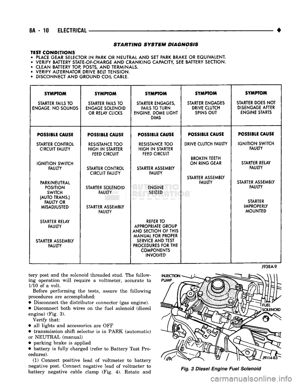
STARTING SYSTEM DIAGNOSIS
TEST CONDITIONS • PLACE GEAR SELECTOR
IN
PARK OR NEUTRAL AND SET PARK BRAKE
OR
EQUIVALENT. • VERIFY BATTERY STATE-OF-CHARGE AND CRANKING CAPACITY, SEE BATTERY SECTION.
• CLEAN BATTERY TOP, POSTS, AND TERMINALS.
• VERIFY ALTERNATOR DRIVE BELT TENSION.
• DISCONNECT AND GROUND COIL CABLE. SYMPTOM
SYMPTOM SYMPTOM SYMPTOM SYMPTOM
STARTER FAILS TO STARTER FAILS TO STARTER ENGAGES, STARTER ENGAGES STARTER DOES NOT
ENGAGE.
NO SOUNDS
ENGAGE
SOLENOID FAILS TO TURN DRIVE CLUTCH
DISENGAGE
AFTER
OR RELAY CLICKS ENGINE. DOME
LIGHT
SPINS
OUT
ENGINE STARTS
DIMS
POSSIBLE
CAUSE
POSSIBLE
CAUSE
POSSIBLE
CAUSE
POSSIBLE
CAUSE
POSSIBLE
CAUSE
STARTER CONTROL
RESISTANCE
TOO
RESISTANCE
TOO DRIVE CLUTCH
FAULTY
IGNITION
SWITCH
CIRCUIT
FAULTY
HIGH
IN
STARTER
HIGH
IN
STARTER
FAULTY
FEED CIRCUIT FEED CIRCUIT
BROKEN
TEETH
IGNITION
SWITCH ON RING GEAR
STARTER RELAY
FAULTY
STARTER CONTROL STARTER ASSEMBLY
FAULTY
CIRCUIT
FAULTY FAULTY
STARTER ASSEMBLY
PARK/NEUTRAL
FAULTY
STARTER ASSEMBLY
POSITION STARTER SOLENOID ENGINE
FAULTY
SWITCH
FAULTY
SEIZED
(AUTO
TRANS.) STARTER
FAULTY
OR STARTER
MISADJUSTED STARTER ASSEMBLY IMPROPERLY
FAULTY
MOUNTED
STARTER RELAY
REFER
TO
FAULTY
APPROPRIATE GROUP
AND SECTION OF THIS
MANUAL FOR PROPER
STARTER ASSEMBLY
SERVICE
AND TEST
FAULTY
PROCEDURES
FOR THE
COMPONENTS INVOLVED
J938A-9
tery post and the solenoid threaded stud. The follow
ing operation will require a voltmeter, accurate to 1/10 of a volt.
Before performing the tests, assure the following
procedures are accomplished:
•
Disconnect the distributor connector (gas engine).
•
Disconnect both wires on the fuel solenoid (diesel engine) (Fig. 3). Verify that:
•
all lights and accessories are OFF
•
transmission shift selector is in PARK (automatic)
or NEUTRAL (manual)
•
parking brake is applied
•
battery is fully charged (refer to Battery Test Pro
cedures). (1) Connect positive lead of voltmeter to battery
negative post. Connect negative lead of voltmeter to
battery negative cable clamp (Fig. 4). Rotate and
Fig.
3
Diesel
Engine
Fuel
Solenoid
Page 335 of 1502
8A
- 14
ELECTRICAL
CASE
GROUND
FIELD
TERMINALS
142-DG/OR
BATTERY
VOLTAGE
ALTERNATOR
CASE
GROUND
GROUND ALTERNATOR
BATTERY
TERMINAL
ENGINE
CONTROLLER TO ENGINE
CONTROLLER TERMINAL
51
LESS
THAN
"BATTERY VOLTAGE
m^mm i
A21 DB-
20
AMP FUSE
A14
RD
AUTO
SHUTDOWN
RELAY
IGNITION
SWITCH
POWER
DISTRIBUTION
CENTER
JUMPER WIRE TO GROUND TEST
AMMETER TEST
VOLTMETER
2
i
DISCONNEaED
ALTERNATOR
OUTPUT
WIRE
ACC
OFF
J938A-17
CARBON
PILE
RHEOSTAT
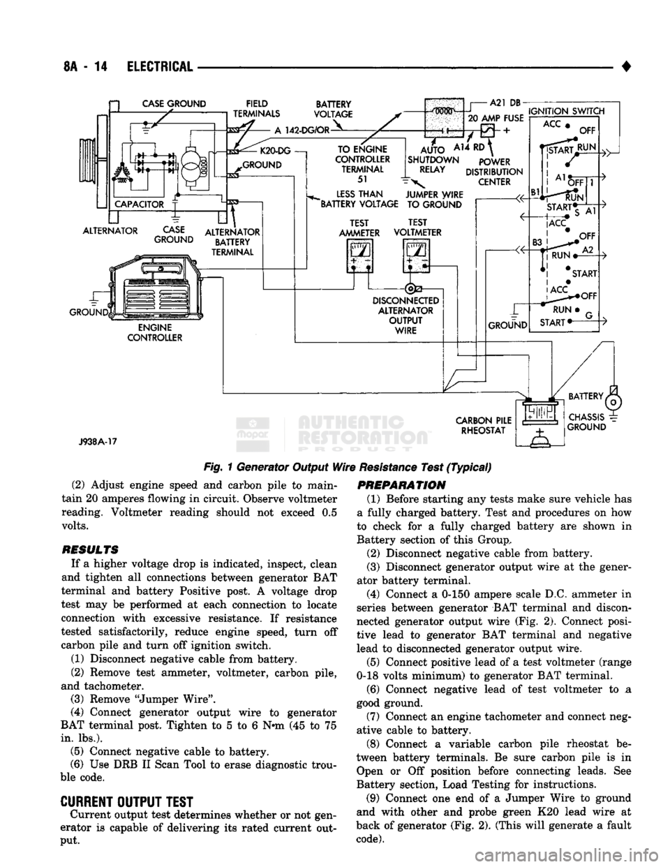
Fig.
1 Generator Output
Wire
Resistance
Test
(Typical)
(2) Adjust engine speed and carbon pile to main
tain 20 amperes flowing in circuit. Observe voltmeter
reading. Voltmeter reading should not exceed 0.5
volts.
RESULTS
If a higher voltage drop is indicated, inspect, clean
and tighten all connections between generator BAT
terminal and battery Positive post. A voltage drop
test may be performed at each connection to locate
connection with excessive resistance. If resistance
tested satisfactorily, reduce engine speed, turn off carbon pile and turn off ignition switch.
(1) Disconnect negative cable from battery.
(2) Remove test ammeter, voltmeter, carbon pile,
and tachometer. (3) Remove "Jumper Wire".
(4) Connect generator output wire to generator
BAT terminal post. Tighten to 5 to 6 Nnn (45 to 75
in.
lbs.). (5) Connect negative cable to battery.
(6) Use DRB II Scan Tool to erase diagnostic trou
ble code.
CURRENT
OUTPUT
TEST
Current output test determines whether or not gen
erator is capable of delivering its rated current out
put.
PREPARATION
(1) Before starting any tests make sure vehicle has
a fully charged battery. Test and procedures on how
to check for a fully charged battery are shown in
Battery section of this Group,
(2) Disconnect negative cable from battery.
(3) Disconnect generator output wire at the gener
ator battery terminal.
(4) Connect a 0-150 ampere scale D.C. ammeter in
series between generator BAT terminal and discon
nected generator output wire (Fig. 2). Connect posi
tive lead to generator BAT terminal and negative
lead to disconnected generator output wire.
(5) Connect positive lead of a test voltmeter (range
0-18 volts minimum) to generator BAT terminal.
(6) Connect negative lead of test voltmeter to a
good ground.
(7) Connect an engine tachometer and connect neg
ative cable to battery.
(8) Connect a variable carbon pile rheostat be
tween battery terminals. Be sure carbon pile is in Open or Off position before connecting leads. See
Battery section, Load Testing for instructions.
(9) Connect one end of a Jumper Wire to ground
and with other and probe green K20 lead wire at
back of generator (Fig. 2). (This will generate a fault
code).
Page 336 of 1502
•
ELECTRICAL
8A - 15 a
CASE
GROUND
CAPACITOR
ALTERNATOR ~L FIELD
TERMINALS
A
142-DG/OR BATTERY
VOLTAGE K20-DG
—!
GROUND
CASE
GROUND
til
ALTERNATOR BATTERY
TERMINAL ENGINE
CONTROLLER TO ENGINE
CONTROLLER TERMINAL
51
LESS
THAN
BATTERY VOLTAGE A21
DB-
.....
IGNITION SWITCH
20 AMP FUSE
AUTO
AH ^
SHUTDOWN POWER
RELAY
DISTRIBUTION
\
CENTER TEST
AMMETER JUMPER WIRE
TO GROUND
TEST
VOLTMETER
GO
5—n
DISCONNECTED
ALTERNATOR OUTPUT WIRE GROUND
ACC
Bl
OFF
RUN OFF
START*T
|ACC
CARBON
PILE RHEOSTAT
J938A-18
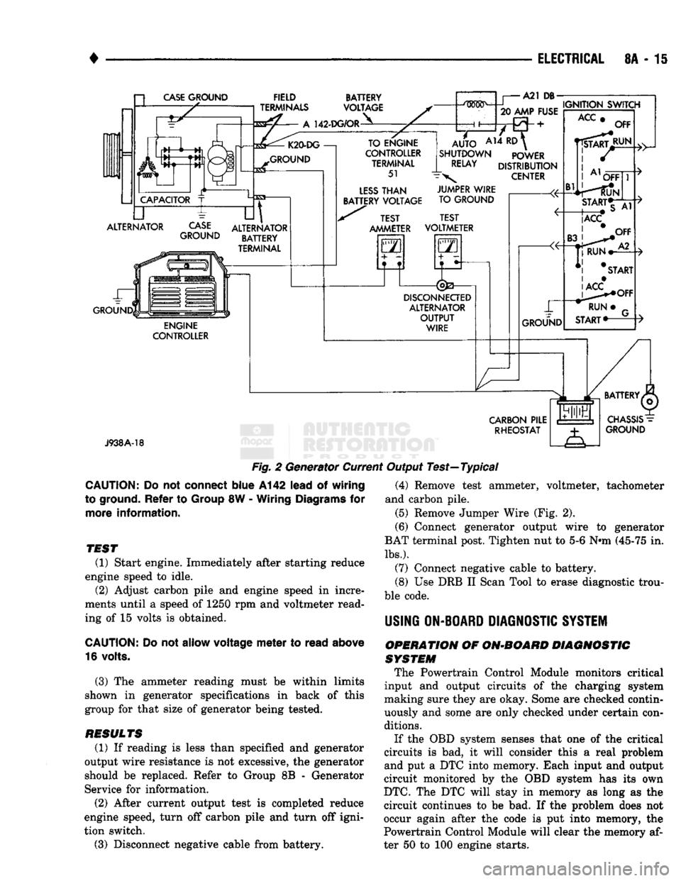
Fig.
2 Generator Current Output Test—Typical
CAUTION:
Do not
connect
blue
A142
lead
of
wiring
to ground.
Refer
to
Group
8W -
Wiring
Diagrams
for
more
information.
TEST
(1) Start engine. Immediately after starting reduce
engine speed to idle. (2) Adjust carbon pile and engine speed in incre
ments until a speed of 1250 rpm and voltmeter read
ing of 15 volts is obtained.
CAUTION:
Do not
allow
voltage
meter
to
read
above
16 volts.
(3) The ammeter reading must be within limits
shown in generator specifications in back of this
group for that size of generator being tested.
RESULTS
(1) If reading is less than specified and generator
output wire resistance is not excessive, the generator
should be replaced. Refer to Group 8B - Generator
Service for information.
(2) After current output test is completed reduce
engine speed, turn off carbon pile and turn off igni
tion switch.
(3) Disconnect negative cable from battery. (4) Remove test ammeter, voltmeter, tachometer
and carbon pile. (5) Remove Jumper Wire (Fig. 2).
(6) Connect generator output wire to generator
BAT terminal post. Tighten nut to 5-6 Nnn (45-75 in.
lbs.).
(7) Connect negative cable to battery.
(8) Use DRB II Scan Tool to erase diagnostic trou
ble code.
USING
ON-BOARD
DIAGNOSTIC
SYSTEM
OPERATION
OF
ON-BOARD
DIAGNOSTIC
SYSTEM
The Powertrain Control Module monitors critical
input and output circuits of the charging system
making sure they are okay. Some are checked contin
uously and some are only checked under certain con
ditions.
If the OBD system senses that one of the critical
circuits is bad, it will consider this a real problem
and put a DTC into memory. Each input and output
circuit monitored by the OBD system has its own
DTC.
The DTC will stay in memory as long as the
circuit continues to be bad. If the problem does not
occur again after the code is put into memory, the
Powertrain Control Module will clear the memory af
ter 50 to 100 engine starts.
Page 621 of 1502
9 - 16
ENGINES
•
CONDITION
POSSIBLE
CAUSES
CORRECTION
EXCESSIVE
VIBRATION
Loose
or broken engine mounts.
Replace
engine mounts.
Damaged
fan or improperly
operating
accessories.
Check
and replace the vibrating components.
Improperly operating vibration
clamper. Inspect/replace the vibration damper.
Improperly operating fan hub. Inspect/replace the fan hub.
Worn
or
damaged
alternator
bearing.
Check/replace
the alternator.
Flywheel
housing
misaligned. Check/correct flywheel alignment.
Loose
or broken power
component.
Inspect
the crankshaft and rods for damage
that
causes
an
unbalance.
Repair/replace as required.
Worn
or unbalanced driveline
components.
Check/repair driveline components.
EXCESSIVE
ENGINE
NOISES
Drive belt squeal, insufficient
tension
or abnormally high
loading.
Check
the tensioner and inspect the drive belt. Make sure water
pump,
tensioner pulley, fan hub and alternator turn
freely.
Intake air or exhaust leaks. Refer to
Excessive
Exhaust
Smoke
(Engine
Diagnosis—
Performance).
Excessive
valve
lash
Adjust
valves.
Make sure the
push
rods are not bent and rocker
levers or adjusting screws are not severely worn. Replace bent
or
severely worn
pads.
Turbocharger
noise.
Check
turbocharger impeller and turbine wheel for housing
contact. Repair/replace as required.
Gear
train
noise.
Visually
inspect and measure gear
backlash.
Replace gears as
required.
Power
function knock.
Check/replace
rod and main bearings.
ALTERNATOR
NOT
CHARGING
OR IN-
SUFFICIENT
CHARGING
Loose
or corroded battery
connections.
Alternator belt slipping. Clean/tighten battery connection.
Check/replace
belt tensioner. Check/replace belt.
Alternator pulley loose on
shaft.
Tighten pulley.
Improperly operating
alternator.
Check/replace
alternator.
J9109-253
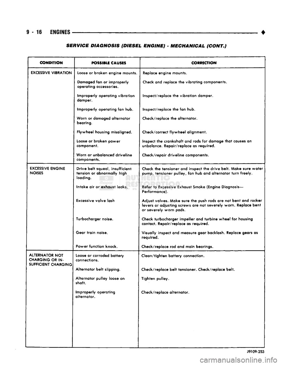
SERVICE DIAGNOSIS (DIESEL ENGINE) - MECHANICAL (CONT.)
Page 756 of 1502
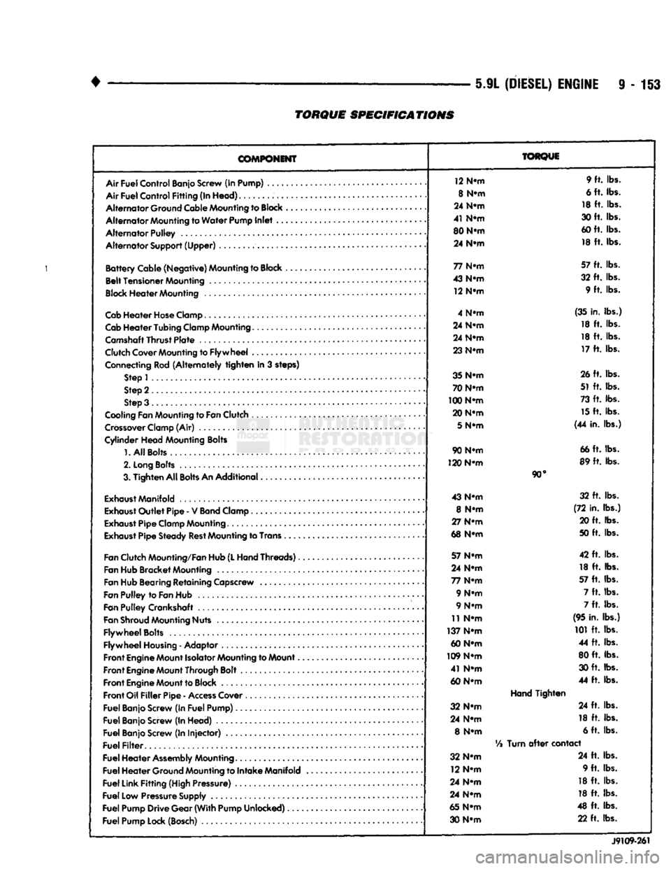
5.9L
(DIESEL)
ENGINE
9-153
TORQUE
SPECIFICATIONS
COMPONENT
Air
Fuel
Control
Banjo Screw (In Pump) ....
Air
Fuel
Control
Fitting
(In
Head)
Alternator
Ground Cable Mounting to
Block
Alternator
Mounting to
Water
Pump
Inlet
..
Alternator
Pulley
Alternator
Support
(Upper)
Battery
Cable
(Negative)
Mounting to Block ,
Belt
Tensioner
Mounting
Block
Heater
Mounting
Cab
Heater
Hose
Clamp
Cab
Heater
Tubing
Clamp Mounting.......
Camshaft
Thrust
Plate
Clutch Cover Mounting to
Flywheel
...
Connecting Rod
(Alternately
tighten
in 3 steps) Step 1
Step 2
Step 3 .
Cooling Fan Mounting to
Fan
Clutch
Crossover
Clamp (Air)
Cylinder
Head
Mounting Bolts
1.
All
Bolts....
2.
Long
Bolts
.........
3.
Tighten
All
Bolts
An
Additional
Exhaust
Manifold
Exhaust
Outlet
Pipe
- V
Band
Clamp
Exhaust
Pipe
Clamp Mounting
Exhaust
Pipe
Steady
Rest
Mounting to Trans .
Fan
Clutch Mounting/Fan Hub
(L
Hand
Threads)..
Fan Hub
Bracket
Mounting
Fan Hub Bearing
Retaining
Capscrew
Fan
Pulley
to
Fan
Hub
Fan
Pulley
Crankshaft .
Fan
Shroud
Mounting Nuts
Flywheel
Bolts
Flywheel
Housing
- Adaptor
Front
Engine
Mount Isolator Mounting to Mount..
Front
Engine
Mount Through Bolt
Front
Engine
Mount to Block
Front
Oil
Filler
Pipe
-
Access
Cover
Fuel
Banjo Screw (In
Fuel
Pump)
Fuel
Banjo Screw (In
Head)
Fuel
Banjo Screw (In
Injector)
Fuel
Filter
Fuel
Heater
Assembly
Mounting
Fuel
Heater
Ground Mounting to
Intake
Manifold
Fuel
Link
Fitting
(High Pressure)
Fuel
Low Pressure Supply
Fuel
Pump
Drive
Gear
(With
Pump
Unlocked)
Fuel
Pump Lock (Bosch)
TORQUE
12 N-m 9 ft. lbs.
8 N-m 6 ft. lbs.
24 N-m 18 ft. lbs.
41 N*m 30 ft. lbs.
80 N-m 60 ft. lbs.
24 N-m 18 ft. lbs.
77 N-m 57 ft. lbs.
43 N-m 32 ft. lbs.
12 N-m 9 ft. lbs.
4 N-m (35 in. lbs.)
24 N-m 18 ft. lbs.
24 N-m 18 ft. lbs.
23 N-m 17 ft. lbs.
35 N-m 26 ft. lbs.
70 N-m 51 ft. lbs.
100 N-m 73 ft. lbs.
20 N-m 15 ft. lbs.
5
N-m (44 in. lbs.)
90 N-m 66 ft. lbs.
120 N-m 89 ft. lbs.
90°
43 N-m 32 ft. lbs.
8 N-m (72 in. lbs.)
27 N-m 20 ft. lbs.
68 N-m 50 ft. lbs.
57 N-m 42 ft. lbs.
24 N-m 18 ft. lbs.
77 N-m 57 ft. lbs.
9 N-m 7 ft. lbs.
9 N-m 7 ft. lbs.
11 N-m (95 in. lbs.)
137 N-m 101 ft. lbs.
60 N-m 44 ft. lbs.
109 N-m 80 ft. lbs.
41 N-m 30 ft. lbs.
60 N-m 44 ft. lbs.
Hand
Tighten
32 N-m 24 ft. lbs.
24 N-m 18 ft. lbs.
8 N-m 6 ft. lbs.
Vi
Turn
after
contact
32 N-m 24 ft. lbs.
12 N-m 9 ft. lbs.
24 N-m 18 ft. lbs.
24 N-m 18 ft. lbs.
65 N-m 48 ft. lbs.
30 N-m 22 ft. lbs.
J9109-261