1993 DODGE TRUCK air conditioner
[x] Cancel search: air conditionerPage 33 of 1502

0 - 14
LUBRICATION
AND
MAINTENANCE
•
ENGINE
MAINTENANCE
INDEX
page
Air
Injection
Systems/Air Pump
. 17
Air-Conditioner
Compressor
21
Battery
19
Cooling System
15
Crankcase
Ventilation
System
17
Diesel Engine
Air Filter
Canister
17
Drive Belts
20
Engine
Air
Cleaner
Filter
Element
16
Engine Break-In
14
Engine
Oil 14
Engine
Oil
Change
and Filter
Replacement
15
Exhaust Gas
Recirculation
(EGR) System
...... 19
page
Exhaust
Manifold
Heat
Control
Valve
. 17
Exhaust System
, 21
Fuel System
18
Hoses
and
Fittings
16
Ignition
Cables,
Distributor
Cap and
Rotor
...... 19
Ignition
Timing
. 19
Oxygen
(02)
Sensor
19
Rubber/Plastic Components
20
Spark Plugs
. 19
Throttle
Control
Linkage
18
Vacuum Operated, Emission
Control
Components
19
ENGINE BREAK-IN
After first starting a new engine, allow it to idle
for 15 seconds before shifting into a drive gear. Also:
• Drive the vehicle at varying speeds less than 88
km/h (55 mph) for the first 480 km (300 miles).
• Avoid fast acceleration and sudden stops.
• Do not drive at full-throttle for extended periods of
time
• Do not drive at constant speeds
• Do not idle the engine excessively A special break-in engine oil is not required. The
original engine oil installed is a high quality lubri
cant. New engines tend to consume more fuel and oil un
til after the break-in period has ended.
ENGINE
OIL SPECIFICATIONS
API SERWICE
GRADE
Use an engine oil that conforms to API Service
Grade S5 SG/CD or SG/CE. MOPAR®provides engine
oils that conform to all of these service grades.
SULFATED ASH—DIESEL ENGINES
Oils that contain an excessive amount of sulfated
ash can cause deposits to develop on Diesel engine
valves. These deposits can result in valve wear.
SAE
WISC0SITY
An SAE viscosity grade is used to specify the vis
cosity of engine oil. SAE 30 specifies a single viscos
ity engine oil.
Engine oils also have multiple viscosities. 10W-30
<
5W-30
1
1 1
F
-20 0 10 20 32 60 80 100
C
-29 -18 -12 -7 0 16 27 38
ANTICIPATED
TEMPERATURE RANGE BEFORE
NEXT
OIL
CHANGE
J9000-39
Fig.
1 Temperature/Engine Oil Viscosity—Gasoline
Engines
-12°C
-18°C 10°F
0°F- 15W-40
-23°c(^-10eF
I
10W-30
WITH
WITHOUT
BLOCK HEATER
BLOCK
SYNTHETIC
OIL
HEATER
10W-30 5W-30
J9100-29
Fig.
2 Temperature/Engine Oil Viscosity—Diesel
Engines
ENERGY
G0NSERWING
OIL
An Energy Conserving type oil is recommended for
gasoline engines. They are designated as either EN
ERGY CONSERVING or ENERGY CONSERVING
II.
OIL
LEVEL
INDICATOR (DIPSTICK)
GASOLINE ENGINES
The engine oil indicator is located at the right
front of the engine.
Page 35 of 1502
0-18
LUBRICATION
AND
MAINTENANCE
•
COOLANT FREEZE PROTECTION
Cooling systems contain a 50/50 mixture of anti
freeze (ethylene glycol) and distilled water. This is
the recommended coolant mixture.
It is recommended that the degree of coolant pro
tection be tested every 12 months. If the coolant is
contaminated or rusty, the cooling system should be
drained, flushed. Refill with a 50/50 mixture of fresh
coolant. Refer to Group 7—Cooling Systems for addi
tional information.
SYSTEM
INSPECTION
WARNING:
IF THE
ENGINE
HAS
BEEN RECENTLY
OPERATED,
DO NOT
REMOVE
THE
RADIATOR
CAP.
THIS WILL AVOID
YOU
BEING SCALDED
WITH
HOT, PRESSURIZED COOLANT.
(1) Test the radiator cap for proper sealing and op
eration. Use caution when removing the radiator cap
to avoid contact with hot coolant. Place a heavy rag
or towel over the cap and turn to the first stop. Do
not press down. Pause to allow the pressure to re
lease through the overflow tube. Then press down
and turn counterclockwise to remove the cap.
(2) Inspect the coolant overflow tubing and the
connections at the coolant reserve tank and at the
radiator.
(3) Inspect the entire cooling system for leaks. A
black-light detector can be used as an aid in detect ing the source of coolant leaks.
(4) Inspect the radiator and air conditioner con
denser fins for debris, etc. (5) If necessary, refer to Group 7—Cooling Systems
for additional information and service procedures.
RADIATOR CAP
The radiator cap must be completely tightened to
provide proper pressure. Inspect and test radiator cap
when cooling system service is performed.
MAIN,
FLUSH
AND
FILL
WARNING: ANTI-FREEZE (ETHYLENE GLYCOL)
IS
POISONOUS.
KEEP
OUT OF THE
REACH
OF
CHIL
DREN.
Drain, flush, and fill the cooling system at the in
terval specified in maintenance schedule. For proper service instructions see Group 7, Cooling System.
HOSES AND
FITTINGS
It is recommended that rubber hoses be periodi
cally inspected. Inspect all hose fittings for looseness and corrosion.
ENGINE
AIR
CLEANER
FILTER
ELEMENT
MAINTENANCE
SCHEDULE
With normal driving conditions, the engine air
cleaner filter element should be replaced:
• Light-Duty Cycle-after each 48 000 km (30,000
miles) interval has elapsed
• Heavy-Duty Cycle-after
each
38 000 km (24,000
miles) interval has elapsed
When the vehicle is operated in dusty areas, the
filter element should be replaced more often.
For Diesel engines, the air filter canister should be
cleaned at the same time the filter is replaced.
SERVICE/REPLACEMENT
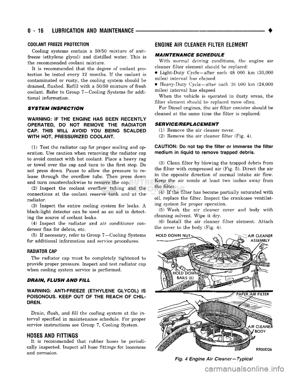
(1) Remove the air cleaner cover.
(2) Remove the air cleaner filter (Fig. 4).
CAUTION:
Do not tap the filter or immerse the filter medium in liquid to remove trapped debris.
(3) Clean filter by blowing the trapped debris from
the filter with compressed air (Fig. 5). Direct the air in the opposite direction of normal intake air flow.
Keep the air nozzle at least two inches away from
the filter.
(4) If the filter has become partially saturated with
oil,
replace the filter. Inspect the crankcase ventilat
ing system for proper operation.
(5) Wash the air cleaner cover and body with
cleaning solvent. Wipe it dry.
(6) Install the air cleaner filter element. Attach
the cover to the body (Fig. 4).
Fig,
4
Engine
Air Oeaner—
Typical
Page 40 of 1502
•
LUBRICATION
AND
MAINTENANCE
0 - 21 ROUTINE INSPECTION
It is recommended that the drive belt(s) be rou
tinely inspected for cracks, fraying and excessive
wear. Replace as necessary.
EXHAUST SYSTEM
An exhaust system must be properly aligned to
prevent stress, leakage, and vehicle body contact.
MAINTENANCE SCHEDULE Inspect the exhaust system at the interval specified
in maintenance schedule.
INSPECTION Inspect for cracked or loose joints, corrosion dam
age,
and worn or broken hangers. Replace all compo
nents that are damaged. Do not attempt repair. Also,
inspect for the following conditions and correct as
necessary:
• Exhaust system leaks, misalignment • Contact with body panels or the frame
• Catalytic converter bulging or excessive heat dam
age
CAUTION:
A
catalytic converter
will
become
con
taminated
if
leaded gasoline
is
burned
in the en
gine.
If
this
occurs,
the
complete converter must
be
replaced.
AIR-CONDITIONER COMPRESSOR LUBRICANT
AND
REFRIGERANT
The lubricant level in the compressor should be
checked if there are indications that oil was lost.
Loss of lubricating oil usually accompanies a loss of
refrigerant. The presence of bubbles in sight glass in dicates that loss of refrigerant has occurred. For additional information involving the A/C sys
tem, refer to Group 24—Heater And Air Condition ing.
Page 821 of 1502
14
- 2
FUEL SYSTEM
•
GASOLINE/OXYGENATE
BLENDS
Some fuel suppliers blend unleaded gasoline with
materials that contain oxygen such as alcohol, MTBE and ETBE. The type and amount of oxygenate used
in the blend is important. The following are gener
ally used in gasoline blends:
ETHANOL
Ethanol (Ethyl or Grain Alcohol) properly blended,
is used as a mixture of 10 percent ethanol and 90
percent gasoline. Gasoline with ethanol may be
used in your vehicle.
METHANOL
CAUTION:
DO NOT USE
GASOLINES CONTAINING
METHANOL.
Use of methanol/gasoline blends may re
sult in starting and driveability problems. In addition,
damage may be done to critical fuel system compo
nents.
Methanol (Methyl or Wood Alcohol) is used in a va
riety of concentrations blended with unleaded gaso
line.
You may encounter fuels containing 3 percent
or more methanol along with other alcohols called co-
solvents.
Problems that are the result of using methanol/gas
oline blends are not the responsibility of Chrysler Corporation. They may not be covered by the vehicle
warranty.
MTBE/ETBE
Gasoline and MTBE (Methyl Tertiary Butyl Ether)
blends are a mixture of unleaded gasoline and up to 15 percent
MTBE.
Gasoline and
ETBE
(Ethyl
Ter
tiary Butyl Ether) are blends of gasoline and up to 17 percent ETBE. Gasoline blended with MTBE or
ETBE may be used in your vehicle.
CLEAN
AIR GASOLINE Many gasolines are now being blended that con
tribute to cleaner air, especially in those areas of the
country where air pollution levels are high. These
new blends provide a cleaner burning fuel and some are referred to as Reformulated Gasoline.
In areas of the country where carbon monoxide lev
els are high, gasolines are being treated with oxy
genated materials such as MTBE, ETBE and ethanol.
Chrysler Corporation supports these efforts toward
cleaner air and recommends that you use these gas
olines as they become available.
FUEL
REQUIREMENTS-DIESEL ENGINE
Use good quality diesel fuel from a reputable sup
plier in your Chrysler Corporation vehicle. For most
year-round service, number 2 (two) diesel fuel meet ing ASTM specification D-975 will provide good per
formance. If the vehicle is exposed to extreme cold (below -18°C - 0°F), or for any reason is required to
operate at colder than normal conditions for pro longed periods, then dilution of the 2D fuel with 50
percent kerosine or number ID diesel fuel will pro
vide better protection from fuel gelling or wax-plug ging of the fuel filters. Diesel fuel is seldom
completely free of water. To prevent fuel system
trouble, including fuel tube (line) freezing in winter, drain the accumulated water using the drain pro
vided. If you buy good quality fuel and follow the cold weather advice above, fuel conditioners should
not be required in your vehicle.
Page 967 of 1502
19
- 6
STEERING
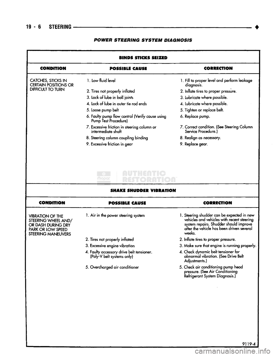
• POWER STEERING SYSTEM DIAGNOSIS
BINDS STICKS SEIZED
CONDITION
POSSIBLE
CAUSE CORRECTION
CATCHES,
STICKS
IN
CERTAIN POSITIONS OR
DIFFICULT
TO TURN
1.
Low
fluid level
2. Tires not properly
inflated
3.
Lack
of
lube
in ball joints
4.
Lack of lube in outer tie rod ends
5.
Loose pump belt
6. Faulty pump flow control (Verify cause using Pump Test Procedure)
7.
Excessive friction in steering column or intermediate shaft
8.
Steering column coupling binding
9. Excessive friction in gear
1.
Fill to proper level
and
perform leakage
diagnosis.
2.
Inflate tires to proper pressure.
3.
Lubricate where possible.
4.
Lubricate where possible.
5.
Tighten or replace belt.
6. Replace pump.
7.
Correct condition. (See Steering Column Service Procedure.)
8. Realign as necessary.
9. Replace gear.
SHAKE SHUDDER
VIBRATION
CONDITION
POSSIBLE CAUSE CORRECTION
VIBRATION
OF THE
STEERING
WHEEL AND/
OR
DASH DURING DRY
PARK
OR LOW
SPEED
STEERING
MANEUVERS
1.
Air in the power steering system
2.
Tires not properly inflated
3.
Excessive engine vibration
4.
Faulty accessory drive belt tensioner. (Poly-V belt systems only)
5.
Overcharged air conditioner
1.
Steering shudder can be expected in new
vehicles and vehicles with recent steering system repairs. Shudder should improve
after the vehicle has been driven several
weeks.
2.
Inflate tires to proper pressure.
3.
Make sure that engine is running properly.
4.
Check dynamic belt tensioner for abnormal vibration. (See Drive Belt
Adjustments.)
5.
Check air conditioning pump head pressure. (See Air
Conditioning
Refrigerant System Diagnosis.)
9119-4
Page 1439 of 1502
24 - 2
HEATING
AND AIR
CONDITIONING
• housing is expelled through the molded rubber drain
tube into the engine compartment. The tube must be
kept open to prevent condensation from collecting in
the bottom of the housing.
The squeezed rubber flap at the drain tube tip is
designed to keep engine compartment air from enter ing into the system yet allow condensation to drain.
If the tip is not properly formed or has been dam
aged, the system will not drain properly. Therefore,
if the tube is damaged, it should be replaced.
• SERVICE VALVES—The service valves at the
compressor suction line and discharge tube are used
to test and service the refrigerant system. A special adapter (Tool C-4803) is required for performance
testing.
OPERATION The compressor increases the pressure and temper
ature of the refrigerant. The heated refrigerant vapor
is then pumped into the condenser where it cools by
giving off heat to air passing over the condenser fins.
As the refrigerant cools in the condenser, it con
denses into a liquid. Still under high pressure, the
liquid refrigerant passes into the receiver. The re
ceiver acts as a reservoir to furnish refrigerant to the
expansion (H) valve at all times. From the receiver,
the high pressure liquid refrigerant passes to the ex pansion (H) valve. The expansion (H) valve meters
refrigerant into the evaporator where a low pressure
is maintained by the suction side of the compressor.
As it enters the evaporator, the refrigerant immedi ately begins to boil by absorbing heat from the air
passing over the evaporator core. Having given up its
heat to boil the refrigerant, the air is cooled and
passes into the passenger compartment of the vehi
cle.
From the evaporator the vaporized refrigerant is
drawn back to the compressor to repeat the cycle. RADIATOR CAP
Air conditioned vehicles must be equipped with a
radiator cap having a holding pressure of 98-122 kPag (14-18 psig). Replace the radiator cap that does
not test within this specification.
CONDENSER Inspect the condenser for obstruction or foreign
matter. Clean if present.
Any obstruction to the free flow of air across the
condenser will decrease heat dissipation from the
condenser. This will in turn decrease the efficiency of
the condenser and decrease the evaporator's effi
ciency. These conditions result in increasing the dis
charge pressure and horsepower load on the engine.
The use of a bug screen is not recommended, it also
will decrease the free flow of air.
Inspect the condenser for bent or damaged fins.
The bent fins on the condenser deflect air flow and
decrease the condenser area.
BUG SCREENS Bug screens should NOT be installed on vehicles
equipped with air conditioning. A bug screen in
stalled in front of the condenser will reduce air flow
and air conditioner performance. Under severe heat
conditions a bug screen may cause the engine to
over-heat.
RESISTOR
BLOCK
The blower motor switch and resistor block, con
trols the speed of the blower motor. The resistor
block consists of 3 helical-wound wire resistors, con nected to terminals which are mechanically attached
to a phenolic board. This assembly is bolted to the
plenum.
The blower switch controls the blower motor speed
by selectively connecting in series one, two, three or none of the resistors to the blower motor.
Page 1454 of 1502
•
HEATING
AND
AIR
CONDITIONING
24-17 REFRIGERANT SYSTEM SERWICE PROCEDURES
INDEX
page
Charging
the
System
19
Correcting
Low
Refrigerant
Level
.............
20
Discharging
the
System
. 19
Evacuating
the
System
19
REFRIGERANT
SAFETY
PRECAUTIONS
WARNING: EXTREME CARE MUST
BE
TAKEN
TO
PREVENT
ANY LIQUID
REFRIGERANT FROM COM
ING
IN
CONTACT
WITH
THE
SKIN
AND
ESPE
CIALLY
THE
EYES.
ALWAYS WEAR SAFETY
GOGGLES WHEN SERVICING
ANY
PART
OF
THE
REFRIGERANT SYSTEM.
IF EYE
CONTACT
IS
MADE,
APPLY
A
FEW
DROPS
OF
MINERAL
OIL
TO
THE
EYES
AND
FLUSH
WITH
WATER
FOR
SEV
ERAL MINUTES.
SEEK
MEDICAL
ATTENTION
IMME
DIATELY.
The refrigerant used
in the air
conditioner system
is Refrigerant-12 (R-12).
R-12 is
nonexplosive, non
flammable, non-corrosive,
has
practically
no
odor
and
is heavier than
air.
Although
it is
classified
as a
safe
refrigerant, certain precautions must
be
observed
to
protect
the
parts involved
and the
person
who is
working
on the
unit. Liquid
R-12, at
normal atmo sphere pressures
and
temperatures, evaporates
so
quickly that
it has the
tendency
to
freeze anything
it
contacts.
WARNING:
TO
AVOID
A
DANGEROUS EXPLOSION,
NEVER
WELD
OR
STEAM CLEAN NEAR
AIR
CON
DITIONING
LINES
OR
COMPONENTS.
DO NOT
HEAT
R-12
ABOVE
52°C (125°F)
BECAUSE
THE
CAN
MAY
EXPLODE.
The
R-12 in the
system
is
always under pressure.
Because
the
system
is
tightly sealed, heat applied
to
any part could cause this pressure
to
build
up
excessively.
WARNING: LARGE AMOUNTS
OF
REFRIGERANT
RELEASED
IN A
CLOSED WORK AREA
WILL
DIS
PLACE
THE
OXYGEN
AND
CAUSE SUFFOCATION.
ALWAYS
MAINTAIN
GOOD
VENTILATION
SUR ROUNDING
THE
WORK AREA.
R-12
gas,
under normal conditions,
is
non-poison
ous.
The
discharge
of R-12 gas
near
an
open flame
page
Pressure Gauge
and
Manifold
Assembly
18
Refrigerant
. 17
Refrigerant
Leak Repair Procedure
20
Service Precautions
. 17
can produce
a
very poisonous
gas
called phosgene.
Phosgene
is
generated when
a
flame-type leak detec
tor
is
used.
CAUTION:
When charging
an A/C
system always
keep
the
tank
in an
upright position.
If the
tank
is
on
its
side
or
upside down,
liquid
refrigerant
will
enter
the
system
and may
damage
the
compressor.
In most instances, moderate heat
is
required
to
bring
the
pressure
of the
refrigerant above system
pressure when charging
or
adding refrigerant.
A
bucket
or
large
pan of hot
water,
not
over 52°C (125°F),
is all the
heat required
for
this purpose.
Do
not heat
the
refrigerant container with
a
blow torch
or
any
other means that would raise
the
temperature and pressure above this temperature.
CAUTION:
Do not
allow
liquid
refrigerant
to
touch
bright
metal.
Refrigerant will tarnish bright metal
and
chrome
surfaces. Avoid splashing
the
refrigerant
on any
sur
face.
Refrigerant
in
combination with moisture
is
very corrosive
and can
cause extensive damage
to all
metal surfaces.
RECYCLING
(R-12) refrigerant
is a
chloroflorocarbon
(CFC)
that
can contribute
to the
depletion
of the
ozone layer
in
the upper atmosphere. Harmful radiation from
the
sun
is
filtered
out by the
ozone.
To
assist
in
protect
ing
the
ozone layer, Chrysler Corporation recom
mends that
an
(R-12) refrigerant recycling device
that meets
SAE
standard
J1991 be
used. Contact
an
automotive service equipment supplier
for
refriger
ant recycling equipment that
is
available
in
your
area. Refer
to the
operating instructions provided
with
the
recycling equipment
for
proper operation.
SERVICE
PRECAUTIONS
Kinks
in the
refrigerant tubing
or
sharp bends
in
the refrigerant hose lines will greatly reduce
the ca
pacity
of the
entire system. High pressures
are
produced
in the
system when
it is
operating. Extreme
care must
be
exercised
to
make sure that
all
connec
tions
are
pressure tight. Dirt
and
moisture
can
enter
Page 1458 of 1502
•
HEATING
AND AIR
CONDITIONING
24 - 21 (a) Loosen both test hoses at the manifold gauge
set. Tighten the hoses as soon as the air is purged. (b) Loosen charging hose connection at manifold
gauge set. This will purge air from the charging
hose.
Tighten connection as soon as air is purged.
(9) With vehicle windows open and hood up, oper
ate engine at 1,300 RPM. (10) Place air conditioner control on A/C and place
the fan switch on high. (11) If necessary, block the condenser to maintain
a discharge pressure of 1 550-1 725 kPag (225-250
psig).
System must be charged through the evapora
tor suction service ports as follows:
(a) Slowly open the suction service gauge valve.
Meter flow of refrigerant by adjusting the suction service gauge valve so the pressure registered at
the suction service gauge does not exceed 345 kPag
COMPRESSOR
J
(50
psig). Keep refrigerant container upright.
(b) Add refrigerant gas until there is no foam visi
ble at the sight glass. As soon as all foam clears, note the weight registered on the refrigerant scale.
(c) Watch the refrigerant weighing scale and add
437 g (14 oz.) of refrigerant (equivalent to 1 can).
(d) Close the suction gauge valve.
CAUTION:
TOO
much
refrigerant
in the
system
can
cause
abnormally high discharge pressures. Care
must
be
used
so the
exact recommended amount
of
refrigerant
is
added
after
foam clears
in the
sight
glass.
(e) Close dispensing manifold valve. Remove test
hoses and adapters from the service ports of com
pressor and install protective caps at service ports.
RVICE (SD-709)
INDEX
page
Compressor
21
Compressor
Shaft Seal
.................... 25
The A/C system uses a 7 piston design Sanden SD-
709 compressor. Designated the SD-709, the compres
sor is mounted on the front right side of the engine
and is driven by a serpentine belt.
System lubrication is provided by 135cc ±15cc (4.6
cu. in. ±0.5 cu. in.) of 500 viscosity refrigerant oil.
The clutch used on the compressor consists of 3 ba
sic components:
(1) The pulley.
(2) The front plate. (3) The field coil.
The pulley and field coil are attached to the front
head of the compressor with snap rings. The hub is keyed to the compressor shaft and is retained on the
shaft with a self-locking nut. Special service tools are
required to remove and install the clutch plate on
the compressor shaft.
COMPRESSOR
REMOVAL
(1) Disconnect the negative cable from the battery.
(2) Disconnect the clutch lead wire.
(3) Remove the discharge and inlet (suction) ser
vice valves from the compressor. Plug or tape all the
openings.
(4) Refer to Group 7, Cooling System and remove
the drive belt(s). (5) Remove the bolts and lift the compressor from
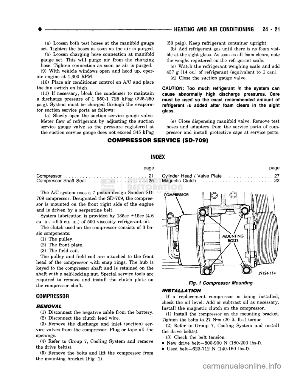
the mounting bracket (Fig. 1).
page
Cylinder Head
/
Valve Plate
27
Magnetic
Clutch
22
Fig.
1
Compressor
Mounting
INSTALLATION
If a replacement compressor is being installed,
check the oil level. Add or subtract oil as necessary.
Install the magnetic clutch on the compressor.
(1) Install the compressor on the mounting bracket.
Tighten the bolts to 27 N*m (20 ft. lbs.) torque.
(2) Refer to Group 7, Cooling System and install
the drive belt(s).
(3) Check the belt tension.
@ New drive belt-800-900 N (180-200 lbs-f).
• Used belt-623-712 N (140-160 lbs-f).