1993 DODGE TRUCK ground locations
[x] Cancel search: ground locationsPage 423 of 1502
8H - 8
VEHICLE SPEED CONTROL SYSTEM
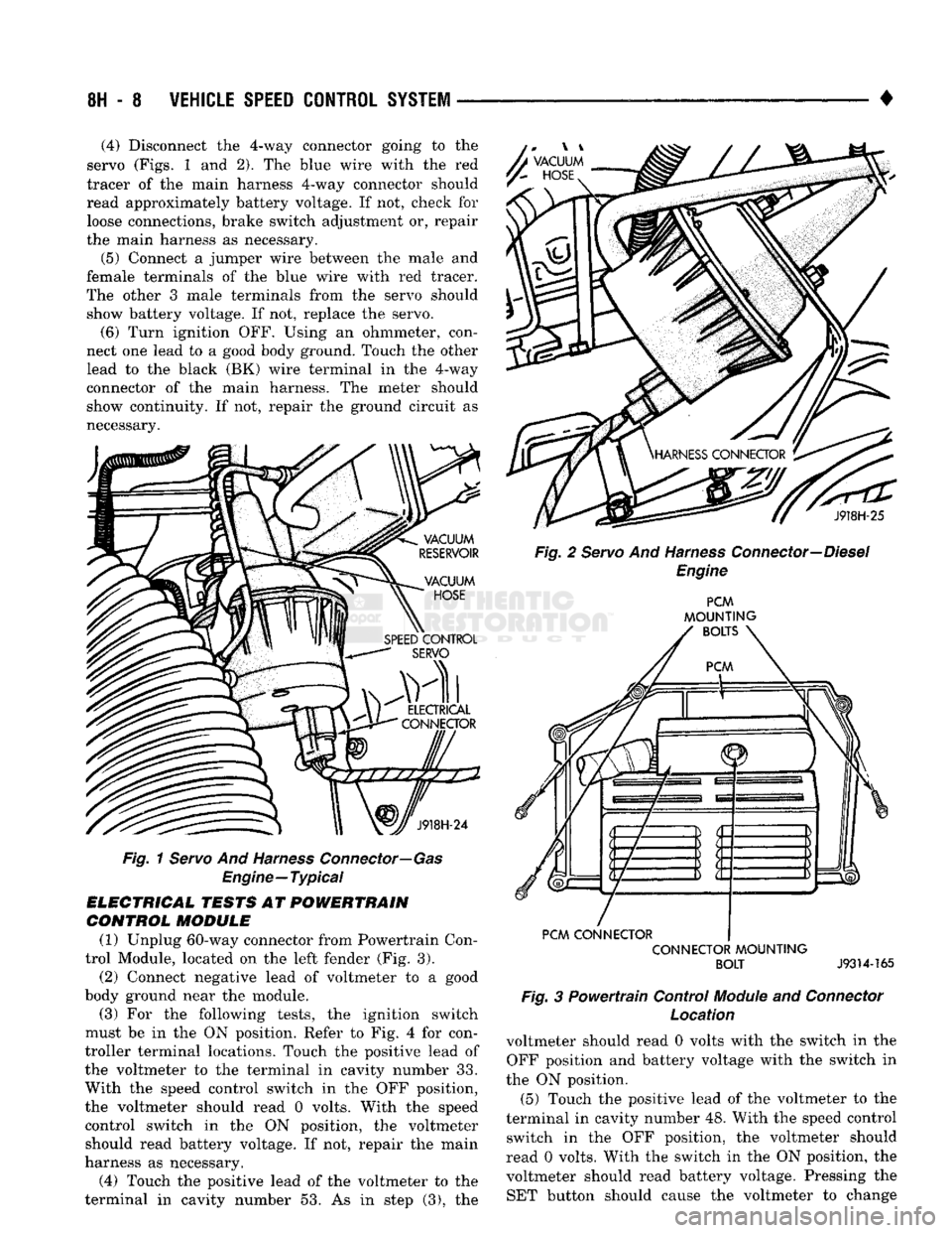
• (4) Disconnect the 4-way connector going to the
servo (Figs. 1 and 2), The blue wire with the red
tracer of the main harness 4-way connector should
read approximately battery voltage. If not, check for loose connections, brake switch adjustment or, repair
the main harness as necessary.
(5) Connect a jumper wire between the male and
female terminals of the blue wire with red tracer.
The other 3 male terminals from the servo should show battery voltage. If not, replace the servo. (6) Turn ignition OFF. Using an ohmmeter, con
nect one lead to a good body ground. Touch the other
lead to the black (BK) wire terminal in the 4-way
connector of the main harness. The meter should
show continuity. If not, repair the ground circuit as
necessary. A
VACUUM
y~
HOSE
J918H-24
Fig.
1 Servo And Harness Connector—Gas
Engine—Typical
ELECTRICAL TESTS AT POWERTRAIN CONTROL MODULE
(1) Unplug 60-way connector from Powertrain Con
trol Module, located on the left fender (Fig. 3).
(2) Connect negative lead of voltmeter to a good
body ground near the module. (3) For the following tests, the ignition switch
must be in the ON position. Refer to Fig. 4 for con
troller terminal locations. Touch the positive lead of
the voltmeter to the terminal in cavity number 33.
With the speed control switch in the OFF position,
the voltmeter should read 0 volts. With the speed
control switch in the ON position, the voltmeter should read battery voltage. If not, repair the main
harness as necessary.
(4) Touch the positive lead of the voltmeter to the
terminal in cavity number 53. As in step (3), the J918H-25
Fig. 2 Servo And Harness Connector—Diesel Engine PCM
MOUNTING
BOLTS
PCM CONNECTOR CONNECTOR MOUNTING BOLT
J9314-165
Fig.
3 Powertrain Control
Module
and
Connector
Location
voltmeter should read 0 volts with the switch in the OFF position and battery voltage with the switch in
the ON position. (5) Touch the positive lead of the voltmeter to the
terminal in cavity number 48. With the speed control switch in the OFF position, the voltmeter should
read 0 volts. With the switch in the ON position, the voltmeter should read battery voltage. Pressing the SET button should cause the voltmeter to change
Page 476 of 1502
•
WIRING DIAGRAMS
8W
- 1
CONTENTS
page page
COMPONENT IDENTIFICATION
.............
9
SPLICE LOCATIONS
29
GENERAL
INFORMATION
1
WIRING DIAGRAMS AD-BODY
37
GENERAL
INFORMATION
INDEX
page
Circuit
Identification
2
Component
Identification
3
Connectors
3
Fusible Links
3
Harness
Repair
3
Locating
A
System
or
Component
2
page
Secondary
Ignition
Wiring
1
Splice Locations
3
Symbols
and
Fuses
5
Troubleshooting
Wiring
Problems
3
Wire Code
Identification
2
Wiring
Diagram Sheets
and
Indexes
1
The wiring diagrams contain
the
latest information
available
at
time
of
publication. Throughout
out
this
group references
may
be
made
to a
particular vehicle
by letter
or
number designation.
A
chart showing
the
breakdown
of
these designations
is
included
in the
Introduction Section
of
this service manual.
SECONDARY
IGNITION WIRING
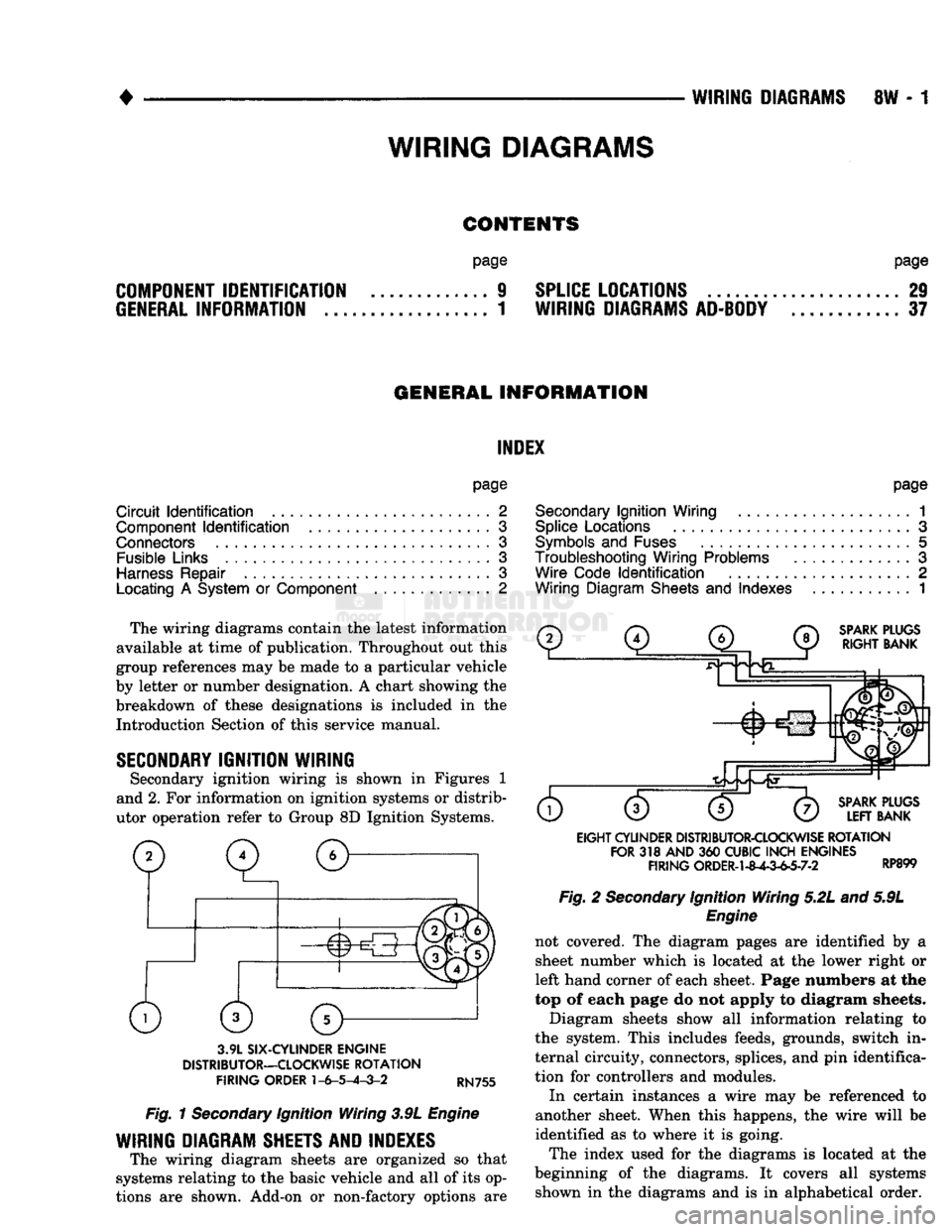
Secondary ignition wiring
is
shown
in
Figures
1
and 2.
For
information
on
ignition systems
or
distrib
utor operation refer
to
Group
8D
Ignition Systems.
SPARK
PLUGS
RIGHT
BANK
3.9L
SIX-CYLINDER
ENGINE
DISTRIBUTOR—CLOCKWISE
ROTATION
FIRING
ORDER
1-6-5-4-3-2
RN755
Fig.
1
Secondary
Ignition Wiring 3.9L
Engine
WIRING DIAGRAM SHEETS AND INDEXES
The wiring diagram sheets
are
organized
so
that
systems relating
to the
basic vehicle
and all of
its op
tions
are
shown. Add-on
or
non-factory options
are
SPARK
PLUGS
LEFT
BANK
EIGHT
CYLINDER
DISTRIBUTOR-CLOCKWISE
ROTATION
FOR
318
AND
360
CUBIC
INCH
ENGINES
FIRING
ORDER-1-8^-3-63-7-2 RP899 Fig.
2
Secondary
Ignition Wiring 5.2L and 5.9L
Engine
not covered.
The
diagram pages
are
identified
by a
sheet number which
is
located
at the
lower right
or
left hand corner
of
each sheet. Page numbers
at the
top
of
each page
do not
apply
to
diagram sheets.
Diagram sheets show
all
information relating
to
the system. This includes feeds, grounds, switch
in
ternal circuity, connectors, splices,
and
pin
identifica
tion
for
controllers
and
modules.
In certain instances
a
wire
may be
referenced
to
another sheet. When this happens,
the
wire will
be
identified
as to
where
it is
going.
The index used
for the
diagrams
is
located
at the
beginning
of the
diagrams.
It
covers
all
systems shown
in the
diagrams
and is in
alphabetical order.
WIRING
DIAGRAMS
Page 478 of 1502
•
WIRING
DIAGRAMS
8W - 3 fer to a components name in the index if you are
unclear as to what a system may be called.
Diagram pages are arranged starting with the bat
tery and fuses. Then working into charging, starting, and ignition systems. After this they start at the
front of the vehicle and work to rear of the vehicle.
The diagrams end with connector identification
pages.
COMPONENT
IDENTIFICATION
To find a components actual location on the vehicle
refer to the wiring and components section index. This section shows the wire harness routing and the compo
nents location in the vehicle. When using this section
refer to the wiring diagrams for the general location of
the component. Then use the component identification index to locate the proper figure number.
SPLICE
LOCATIONS
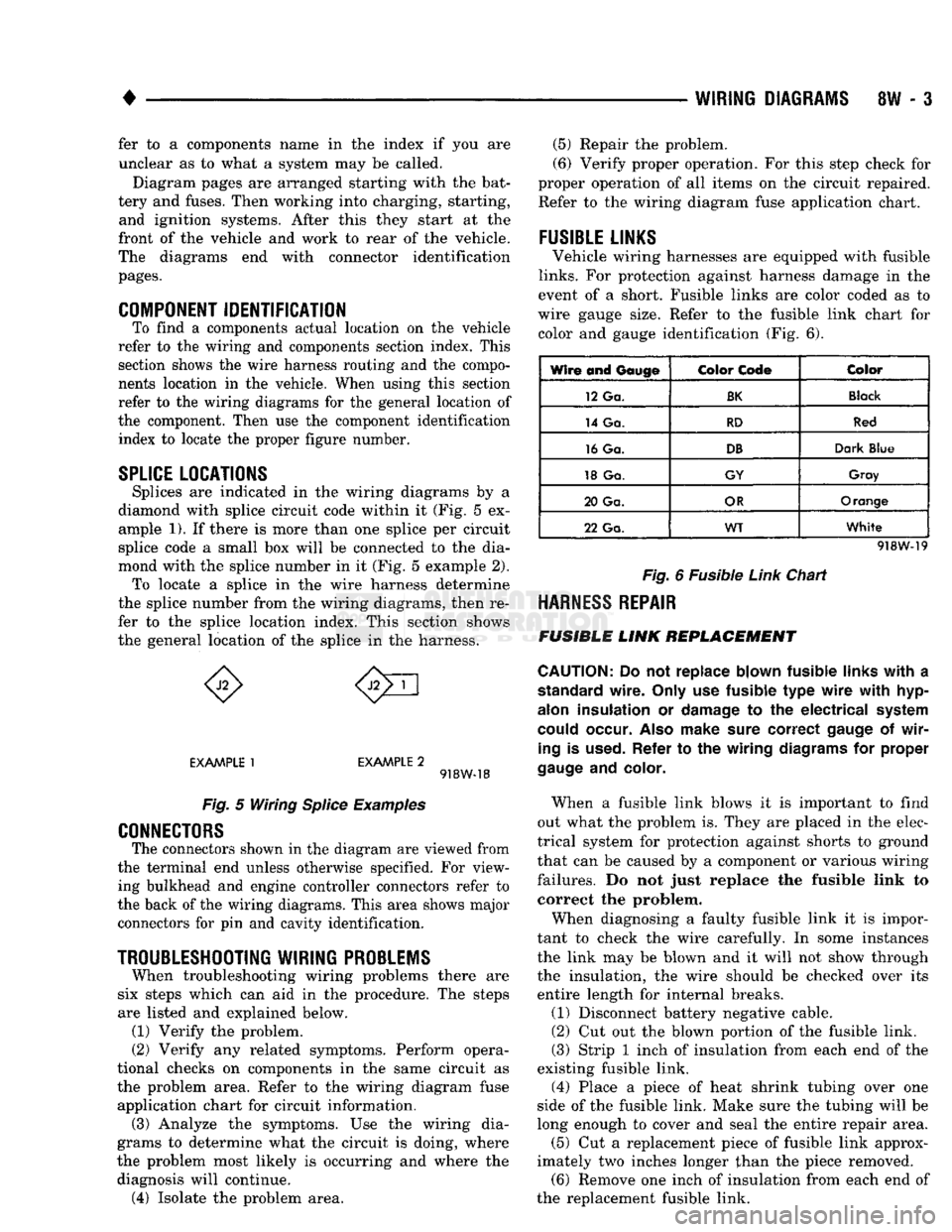
Splices are indicated in the wiring diagrams by a
diamond with splice circuit code within it (Fig. 5 ex ample 1). If there is more than one splice per circuit
splice code a small box will be connected to the dia
mond with the splice number in it (Fig. 5 example 2). To locate a splice in the wire harness determine
the splice number from the wiring diagrams, then re
fer to the splice location index. This section shows
the general location of the splice in the harness.
EXAMPLE
1
EXAMPLE
2 918W-18
Fig.
5 Wiring
Splice
Examples
CONNECTORS
The connectors shown in the diagram are viewed from
the terminal end unless otherwise specified. For view ing bulkhead and engine controller connectors refer to
the back of the wiring diagrams. This area shows major connectors for pin and cavity identification.
TROUBLESHOOTING
WIRING
PROBLEMS
When troubleshooting wiring problems there are
six steps which can aid in the procedure. The steps
are listed and explained below. (1) Verify the problem.
(2) Verify any related symptoms. Perform opera
tional checks on components in the same circuit as the problem area. Refer to the wiring diagram fuse
application chart for circuit information. (3) Analyze the symptoms. Use the wiring dia
grams to determine what the circuit is doing, where
the problem most likely is occurring and where the diagnosis will continue. (4) Isolate the problem area. (5) Repair the problem.
(6) Verify proper operation. For this step check for
proper operation of all items on the circuit repaired. Refer to the wiring diagram fuse application chart.
FUSIBLE
LINKS
Vehicle wiring harnesses are equipped with fusible
links.
For protection against harness damage in the
event of a short. Fusible links are color coded as to
wire gauge size. Refer to the fusible link chart for color and gauge identification (Fig. 6).
Wire and
Gauge
Color
Code
Color
12 Ga.
BK
Black
14 Ga.
RD
Red
16 Ga.
DB
Dark
Blue
18 Ga.
GY
Gray
20 Ga.
OR
Orange
22 Ga.
WT
White
918W-19
Fig.
6 Fusible
Link
Chart
HARNESS
REPAIR
FUSIBLE
LINK
REPLACEMENT
CAUTION:
Do not replace blown fusible
links
with
a
standard
wire.
Only
use fusible type
wire
with
hyp-
alon
insulation or
damage
to the electrical
system
could
occur.
Also
make
sure
correct
gauge
of
wir
ing
is
used.
Refer to the wiring
diagrams
for proper
gauge
and
color.
When a fusible link blows it is important to find
out what the problem is. They are placed in the elec
trical system for protection against shorts to ground
that can be caused by a component or various wiring
failures. Do not just replace the fusible link to correct the problem.
When diagnosing a faulty fusible link it is impor
tant to check the wire carefully. In some instances
the link may be blown and it will not show through the insulation, the wire should be checked over its
entire length for internal breaks.
(1) Disconnect battery negative cable.
(2) Cut out the blown portion of the fusible link.
(3) Strip 1 inch of insulation from each end of the
existing fusible link.
(4) Place a piece of heat shrink tubing over one
side of the fusible link. Make sure the tubing will be
long enough to cover and seal the entire repair area.
(5) Cut a replacement piece of fusible link approx
imately two inches longer than the piece removed. (6) Remove one inch of insulation from each end of
the replacement fusible link.
Page 724 of 1502
•
5.9L (DIESEL) ENGINE
9 - 119
INTEGRAL VALWE SEAT GRINDING
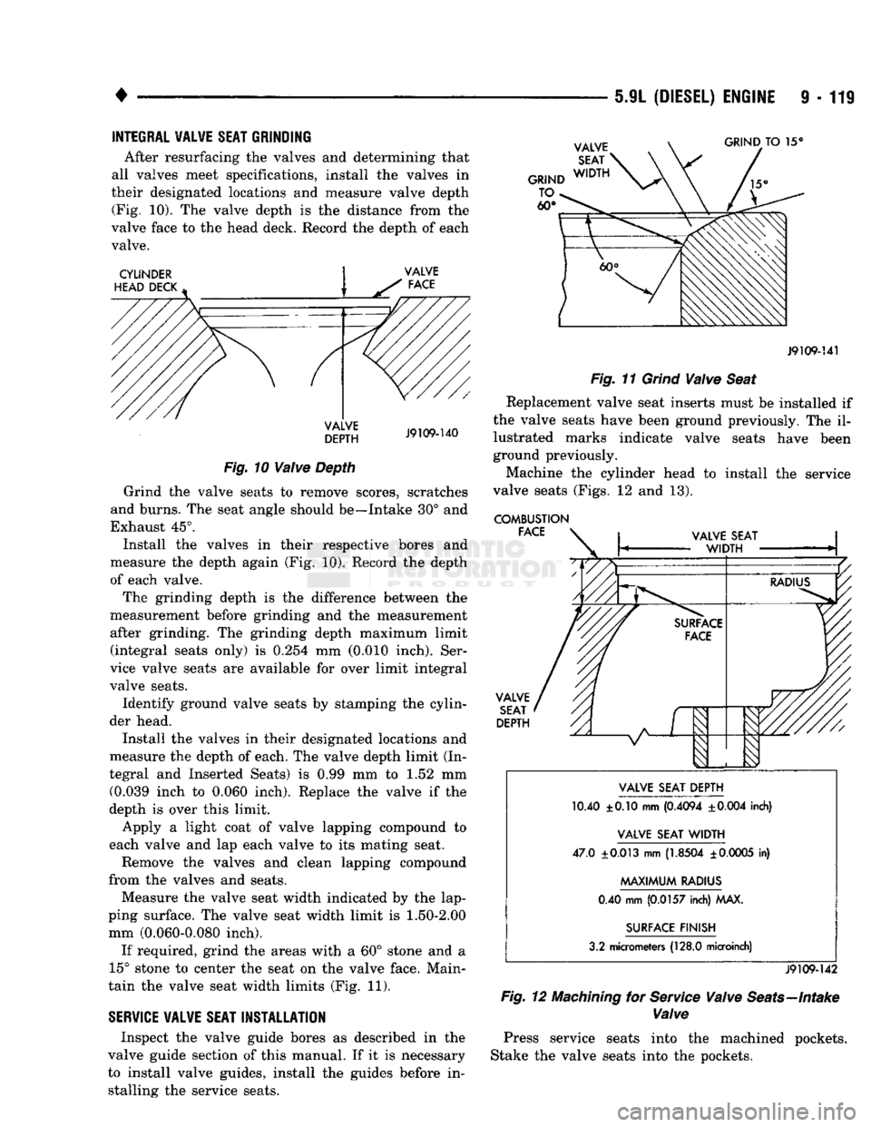
After resurfacing the valves and determining that
all valves meet specifications, install the valves in
their designated locations and measure valve depth (Fig. 10). The valve depth is the distance from the
valve face to the head deck. Record the depth of each valve.
CYLINDER
HEAD DECK GRIND
TO 15°
VALVE
DEPTH
J9109-140
Fig.
10
Valve
Depth
Grind the valve seats to remove scores, scratches
and burns. The seat angle should be—Intake 30° and
Exhaust 45°. Install the valves in their respective bores and
measure the depth again (Fig. 10). Record the depth
of each valve.
The grinding depth is the difference between the
measurement before grinding and the measurement after grinding. The grinding depth maximum limit (integral seats only) is 0.254 mm (0.010 inch). Ser
vice valve seats are available for over limit integral
valve seats.
Identify ground valve seats by stamping the cylin
der head.
Install the valves in their designated locations and
measure the depth of each. The valve depth limit (In
tegral and Inserted Seats) is 0.99 mm to 1.52 mm (0.039 inch to 0.060 inch). Replace the valve if the
depth is over this limit.
Apply a light coat of valve lapping compound to
each valve and lap each valve to its mating seat.
Remove the valves and clean lapping compound
from the valves and seats.
Measure the valve seat width indicated by the lap
ping surface. The valve seat width limit is
1.50-2.00
mm (0.060-0.080 inch).
If required, grind the areas with a 60° stone and a
15° stone to center the seat on the valve face. Main
tain the valve seat width limits (Fig. 11).
SERVICE
VALVE
SEAT
INSTALLATION
Inspect the valve guide bores as described in the
valve guide section of this manual. If it is necessary
to install valve guides, install the guides before in stalling the service seats.
J9109-141
Fig.
11
Grind
Valve
Seat
Replacement valve seat inserts must be installed if
the valve seats have been ground previously. The il lustrated marks indicate valve seats have been
ground previously.
Machine the cylinder head to install the service
valve seats (Figs. 12 and 13).
COMBUSTION FACE VALVE
SEAT
DEPTH VALVE SEAT DEPTH
10.40 ±0.10 mm
(0.4094
±0.004
inch)
VALVE SEAT
WIDTH
47.0
±0.013
mm
(1.8504
±
0.0005
in)
MAXIMUM
RADIUS
0.40 mm
(0.0157
inch) MAX.
SURFACE FINISH
3.2 micrometers
(128.0
microinch)
J9109-142
Fig.
12
Machining
for
Service
Valve
Seats—Intake
Valve
Press service seats into the machined pockets.
Stake the valve seats into the pockets.
Page 863 of 1502
14 - 44
FUEL
SYSTEM
•
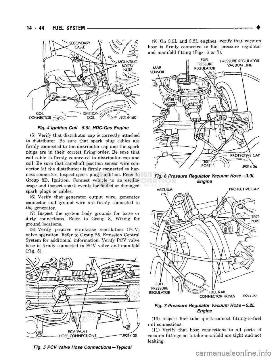
Fig.
4 ignition Coil—5.9L
HDC-Gas
Engine
(5) Verify that distributor cap is correctly attached
to distributor. Be sure that spark plug cables are
firmly connected to the distributor cap and the spark
plugs are in their correct firing order. Be sure that coil cable is firmly connected to distributor cap and
coil. Be sure that camshaft position sensor wire con
nector (at the distributor) is firmly connected to har
ness connector. Inspect spark plug condition. Refer to Group 8D, Ignition. Connect vehicle to an oscillo
scope and inspect spark events for fouled or damaged
spark plugs or cables.
(6) Verify that generator output wire, generator
connector and ground wire are firmly connected to
the generator. (7) Inspect the system body grounds for loose or
dirty connections. Refer to Group 8, Wiring for
ground locations. (8) Verify positive crankcase ventilation (PCV)
valve operation. Refer to Group 25, Emission Control System for additional information. Verify PCV valve
hose is firmly connected to PCV valve and manifold (Fig. 5).
Fig.
5 PCV
Valve
Hose
Connections—Typical (9) On 3.9L and 5.2L engines, verify that vacuum
hose is firmly connected to fuel pressure regulator and manifold fitting (Figs. 6 or 7).
CONNECTOR
HOSES
J9214-27
Fig.
7
Pressure
Regulator
Vacuum
Hose—5.2L
Engine
(10) Inspect fuel* tube quick-connect fitting-to-fuel
rail connections. (11) Verify that hose connections to all ports of
vacuum fittings on intake manifold are tight and not leaking.