1993 DODGE TRUCK diagnostic codes
[x] Cancel search: diagnostic codesPage 249 of 1502
i - 62
BRAKES
•
Isolation/Dump
Valve Cycle Times
Activation (opening/closing) of the isolation and
dump valves is continuous during antilock operation.
The valves cycle rapidly in response to speed sensor inputs and control module signal commands. Cycle
times are measured in milliseconds.
As the demand for antilock mode brake operation
is decreased, the module deactivates the hydraulic
valve components to restore normal brake operation.
ANTILOCK
SERVICE
DIAGNOSIS
GENERAL INFORMATION An antilock system malfunction will be indicated
by illumination of the amber antilock warning lamp.
The red brake warning lamp may also illuminate.
If a problem occurs, system diagnosis should begin
with a fluid level check followed by a visual exami
nation of the system electrical and hydraulic connec
tions.
If obvious defects (low fluid, leaks, loose connections, etc.) are not evident, road test the vehi
cle.
A road test should help determine if a malfunc
tion is actually related to an antilock component.
During the road test, note if other conditions are
evident such as a low pedal, pull, grab, or similar condition. Remember that brake malfunctions such as low fluid, system leaks, parking brakes partially
applied, will also affect the antilock system. The idea
is to determine if a malfunction is actually related to
an anti-lock component.
If a road test does reveal a problem, repeat the
road test with the owner driving. Make sure the owner is not riding the brake pedal, or has forgotten
to release the parking brakes. Either situation will
generate a fault and cause the antilock light to illu
minate.
SYSTEM FAULT
CODES
The antilock control module generates flash codes
to help identify the cause of an antilock system fault. Two different control modules are used with the
1992/1993 RWAL system. A type I module is used in
some early production models. All remaining produc
tion models are equipped with a type II module. The type I and II modules are identified by the way
fault codes 9 and 11 are processed. If the vehicle has a type I module, codes 9 and 11 are not erased when
the ignition switch is turned to Off position. If the vehicle has a type II module, codes 9 and 11 are
erased when the switch is turned to Off.
FAULT CODES WITH TYPE I CONTROL
MODULE
The microprocessor in the electronic control module
has a memory and a self test feature. The self test
feature is activated whenever the ignition switch is
turned to Accessory or Run position. If a system fault is detected, the control module il
luminates the antilock light and stores the fault code
in memory. Fault codes are retained in memory even after turning the ignition switch to Off position.
FAULT CODES WITH TYPE II CONTROL
MODULE The microprocessor in the electronic control module
has a memory and a self test feature. The self test
feature is activated whenever the ignition switch is
turned to Accessory or Run position.
If a system fault is detected, the control module
will illuminate the antilock indicator lamp and store
fault codes 1 through 8, 10 and 12 through 15 in the
microprocessor memory. When one of these fault
codes is generated, the control module will retain the code after the ignition switch is turned to the Off po
sition.
When fault code 9 is generated, the code only re
mains in microprocessor memory while the ignition switch is in Run position. Turning the ignition
switch to Off position erases fault code 9. However, if
the problem still exists when the switch is turned
back to Run position, code 9 will reappear in memory after 20 seconds and the antilock light will illumi
nate once again.
When fault code 11 is generated, the antilock light
will illuminate when vehicle speed exceeds approxi mately 60.35 km/h (37.5 mph). Code 11 only remains in memory while the ignition switch is in the Run
position and the fault is present.
When the cause of a fault code 11 is corrected, the
antilock light goes off. Code 11 is erased when the ig
nition switch is turned to Off position. However, if
the problem cause still exists when the ignition switch is turned to Run position, code 11 will reap
pear when vehicle speed exceeds approximately 60.35 km/h (37.5 mph).
FAULT
CODE
CAPACITY
The microprocessor memory will store and display
only one fault code at a time. The stored code can be
displayed by grounding the RWAL diagnostic connec
tor.
FAULT
CODE
IDENTIFICATION
To determine what the fault code is, momentarily
ground the RWAL diagnostic connector and count
the number of times the amber antilock lamp flashes. Fault codes and typical malfunctions are outlined in Figure 8. Note that when a fault code is gen
erated, the red brake warning lamp will also
illuminate. The initial flash will be a long flash followed by a
number of short flashes. The long flash indicates the
beginning of the fault number sequence and the short flashes are a continuation of that sequence.
Page 334 of 1502
•
ELECTRICAL
8A - 13 GENERATOR TEST PROCEDURES ON
VEHICLE
INDEX
page
Current
Output
Test
......................
14
Diagnostic Procedures
13
General
Information
13
Generator
Output
Wire Resistance Test
.......
13
page
How
to
Use
Malfunction
Indicator
(Check Engine) Lamp
for
Fault
Codes
17
Operational Check
with
Voltmeter
............
13
Using
On-Board Diagnostic System
15
GENERAL
INFORMATION
The generator
is
belt-driven
by the
engine.
All en
gines
use
serpentine drive. The amount
of DC
current produced
by the
gener
ator
is
controlled
by the
Powertrain Control Module (PCM).
All vehicles
are
equipped with
On
Board Diagnos
tics (OBD).
All OBD
sensing systems
are
monitored
by
the PCM. The PCM
will store
in
electronic mem ory
any
detectable failure within
the
monitored cir
cuits.
Refer
to
USING ON-BOARD DIAGNOSTIC SYSTEM
in
this group
for
more information.
OPERATIONAL CHECK
WITH
VOLTMETER
When
the
ignition switch
is
turned
to the RUN po
sition, battery potential will register
on the
voltme
ter. During engine cranking
a
lower voltage will appear
on the
meter. With
the
engine running,
a
voltage reading higher than
the
first reading (igni
tion
in RUN)
should register.
DIAGNOSTIC PROCEDURES
If
the
indicator does
not
operate properly,
or if an
undercharged
or
overcharged battery condition
oc
curs,
the
following procedures
may be
used
to
diag
nose
the
charging system. Remember that
an
undercharged battery
is
often
caused
by:
• accessories being left
on
overnight
•
or by a
defective switch which allows
a
bulb, such
as a
trunk
or
glove
box
light,
to
stay
on
(refer
to
Ignition
Off
Draw).
WISUAL
INSPECTION
• Inspect condition
of
battery cable terminals, bat
tery posts, connections
at
engine block, starter motor solenoid
and
relay. They should
be
clean
and
tight.
Repair
as
required.
• Inspect
all
fuses
in the
fuse block
for
tightness
in
receptacles. They should
be
properly installed
and
tight. Repair
or
replace
as
required.
• Inspect generator mounting bolts
for
tightness.
Re
place
or
torque bolt
as
required (refer
to
Torque Specifications).
• Inspect generator drive belt condition
and
tension.
Tension
or
replace belt
as
required. Refer
to
Belt
Tension Specifications. • Inspect connection
at
generator
B+
output.
It
should
be
clean
and
tight. Repair
as
required.
GENERATOR
OUTPUT
WIRE RESISTANCE TEST
(FIG.
1)
Generator output wire resistance test will show
amount
of
voltage drop across generator output wire
between generator
BAT
terminal
and
battery posi tive post.
PREPARATION
(1) Before starting test make sure vehicle
has a
fully charged battery. Test
and
procedures
on how to
check
for a
fully charged battery
are
shown
in
Bat
tery section
of
this Group.
(2) Turn
OFF
ignition switch.
(3)
Disconnect negative cable from battery.
(4)
Disconnect generator output wire from genera
tor output Battery terminal. (5) Connect
a 0-150
ampere scale
D.C.
ammeter
in
series between generator
BAT
terminal
and
discon
nected generator output wire. Connect Positive lead
to generator
BAT
terminal
and
Negative lead
to
dis connected generator output wire. (6) Connect Positive lead
of a
test voltmeter
(Range
0-18
volts minimum)
to
disconnected genera
tor output wire. Connect negative lead
of
test voltme
ter
to
battery positive cable
at
positive post. (7) Connect
one end of a
Jumper Wire
to
ground
and with other
end
probe green
K20
lead wire
at
back
of
generator
(Fig. 1).
(This will generate
a
fault
code).
CAUTION:
Do not
connect blue
A142
lead
of
wiring
to ground. Refer
to
Group
8W
-
Wiring Diagrams
for
more information.
(8) Connect
an
engine tachometer
and
connect neg
ative cable
to
battery.
(9) Connect
a
variable carbon pile rheostat
be
tween battery terminals.
Be
sure carbon pile
is in
"Open"
or "Off
position before connecting leads.
See
Battery Section, Load Testing
for
instructions.
TEST
(1) Start engine. Immediately after starting,
re
duce engine speed
to
idle.
Page 338 of 1502
•
ELECTRICAL
8A - 17
DIAGNOSTIC
TROUBLE
CODES
Diagnostic trouble codes are 2 digit numbers
flashed on Malfunction Indicator lamp (Check En
gine) that identify which circuit is bad. In most cases
they do not identify which component in a circuit is
bad. A DTC description can be read using the DRB II scan tool. Refer to Group 14 - Fuel Systems for more
information. Therefore, a DTC is only a result, not
necessarily the reason for the problem. However, in
some cases, as a result of the design of the driveabil- ity test procedure, a DTC can be the reason for the
problem. It is important that the test procedure be followed in order to understand what the DTC of the
on-board diagnostic system are trying to tell.
HOW
TO
USE
MALFUNCTION
INDICATOR
(CHECK
ENGINE)
LAMP
FOR
FAULT
CODES
To activate this function cycle the ignition switch
on-off-on-off-on within 5 seconds and any DTC stored
in the Powertrain Control Module will be displayed.
The Check Engine lamp will display a DTC by flash ing on and off. There is a short pause between
flashes and a longer pause between digits. All codes
displayed are two digit numbers with a four second
pause between codes. An example of a code is as follows:
(1) Lamp on for 2 seconds, then turns off.
(2) Lamp flashes 4 times pauses and then flashes
1.
(3) Lamp pauses for 4 seconds, flashes 4 times,
pauses and then flashes 7 times.
The two codes are 41 and 47. Any number of codes
can be displayed (maximum of 8 faults can be stored) as long as they are in memory. The lamp will flash
until all of them (including 55) are displayed (55 =
End of test).
CHARGING
SYSTEM
FAULT
CODES
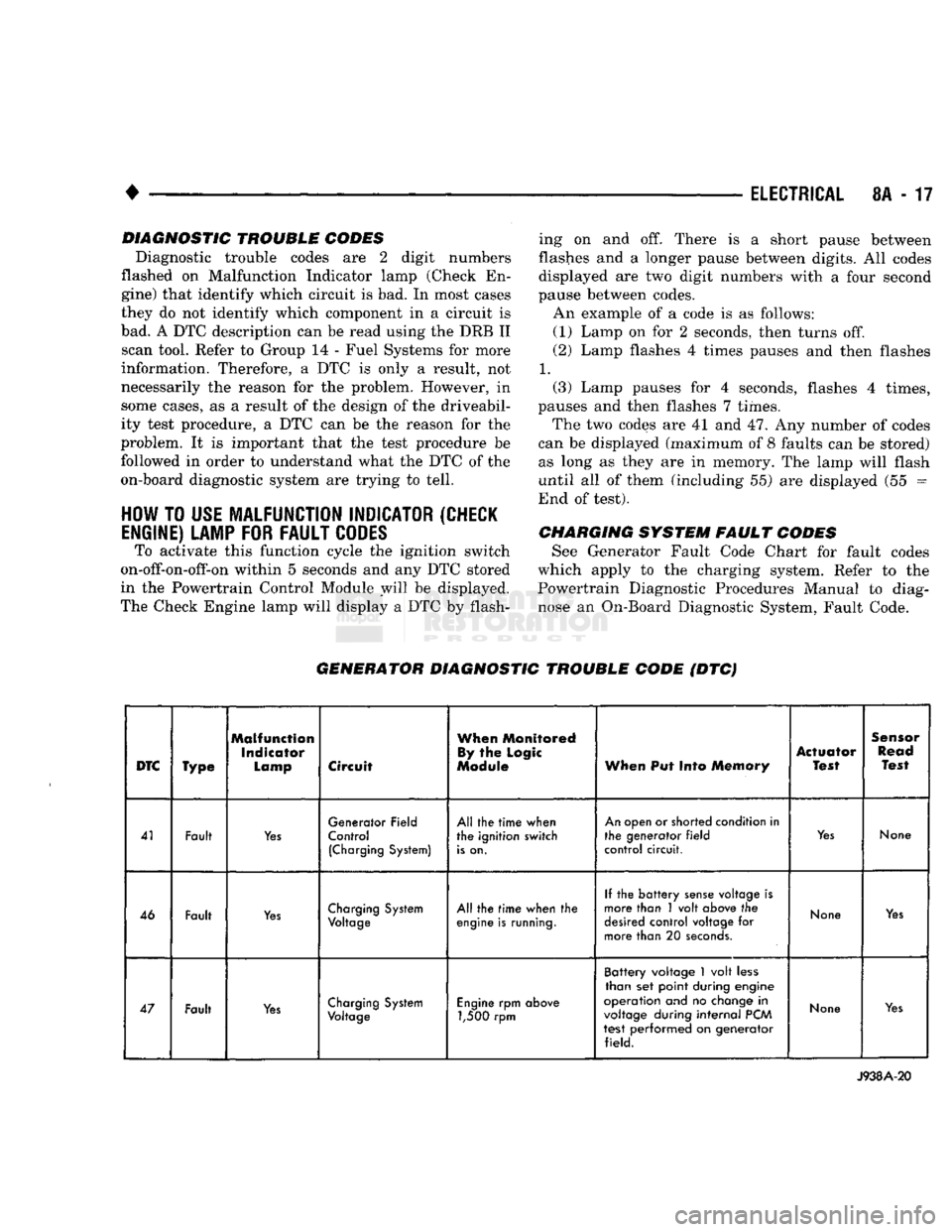
See Generator Fault Code Chart for fault codes
which apply to the charging system. Refer to the
Powertrain Diagnostic Procedures Manual to diag
nose an On-Board Diagnostic System, Fault Code.
GENERATOR
DIAGNOSTIC
TROUBLE
CODE
(DTC)
DTC
Type
Malfunction
Indicator
Lamp
Circuit
When
Monitored
By
the
Logic
Module
When
Put Into
Memory
Actuator
Test
Sensor
Read
Test
41 Fault
Yes
Generator Field
Control
(Charging
System)
All the
time
when
the ignition switch
is
on.
An
open or shorted condition in
the generator
field
control circuit.
Yes
None
46 Fault
Yes
Charging
System
Voltage
All the
time
when the
engine
is
running.
If the
battery
sense
voltage is
more than 1 volt
above
the
desired
control voltage for
more than 20
seconds.
None
Yes
47 Fault
Yes
Charging
System
Voltage
Engine
rpm
above
1,500 rpm Battery voltage
1
volt
less
than set point during engine
operation and no
change
in
voltage
during
internal
PCM
test performed on generator field.
None
Yes
J938A-20
Page 856 of 1502
•
FUEL SYSTEM
14 - 37 used only on vehicles equipped with the 5.9L heavy
duty cycle (HDC) engine. Refer to Group 25, Emis
sion Control System for information.
EVAP CANISTER PURGE SOLENOID-PCM
OUTPUT
Refer to Group 25, Emission Control System. See
EVAP Canister Purge Solenoid.
FUEL INJECTORS-PCM
OUTPUT
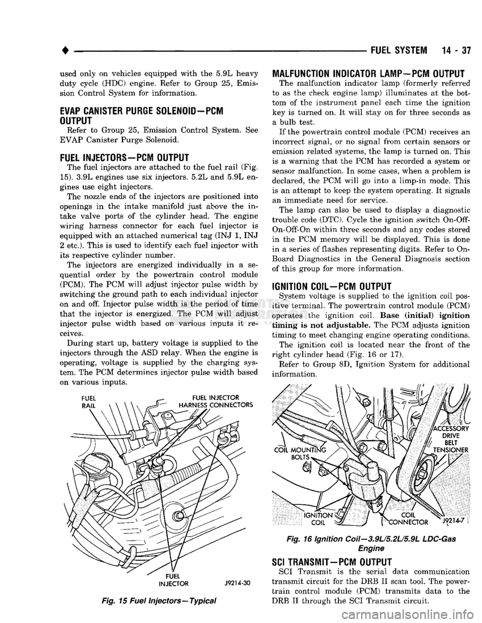
The fuel injectors are attached to the fuel rail (Fig.
15).
3.9L engines use six injectors. 5.2L and 5.9L en
gines use eight injectors. The nozzle ends of the injectors are positioned into
openings in the intake manifold just above the in
take valve ports of the cylinder head. The engine
wiring harness connector for each fuel injector is equipped with an attached numerical tag (INJ 1, INJ 2 etc.). This is used to identify each fuel injector with
its respective cylinder number. The injectors are energized individually in a se
quential order by the powertrain control module (PCM). The PCM will adjust injector pulse width by
switching the ground path to each individual injector
on and off. Injector pulse width is the period of time
that the injector is energized. The PCM will adjust injector pulse width based on various inputs it re
ceives. During start up, battery voltage is supplied to the
injectors through the ASD relay. When the engine is
operating, voltage is supplied by the charging sys
tem. The PCM determines injector pulse width based on various inputs.
FUEL
INJECTOR
J9214-30
Fig.
15
Fuel
injectors—Typical
MALFUNCTION INDICATOR LAMP-PCM OUTPUT
The malfunction indicator lamp (formerly referred
to as the check engine lamp) illuminates at the bot
tom of the instrument panel each time the ignition key is turned on. It will stay on for three seconds as a bulb test. If the powertrain control module (PCM) receives an
incorrect signal, or no signal from certain sensors or
emission related systems, the lamp is turned on. This
is a warning that the PCM has recorded a system or
sensor malfunction. In some cases, when a problem is
declared, the PCM will go into a limp-in mode. This
is an attempt to keep the system operating. It signals an immediate need for service. The lamp can also be used to display a diagnostic
trouble code (DTC). Cycle the ignition switch
On-Off-
On-Off-On within three seconds and any codes stored
in the PCM memory will be displayed. This is done
in a series of flashes representing digits. Refer to On-
Board Diagnostics in the General Diagnosis section
of this group for more information.
IGNITION COIL-PCM OUTPUT
System voltage is supplied to the ignition coil pos
itive terminal. The powertrain control module (PCM)
operates the ignition coil. Base (initial) ignition
timing is not adjustable. The PCM adjusts ignition
timing to meet changing engine operating conditions. The ignition coil is located near the front of the
right cylinder head (Fig. 16 or 17). Refer to Group 8D, Ignition System for additional
information.
Fig.
16 Ignition Coii-3.9U5.2U5.9L
LDC-Gas
Engine
SCI
TRANSMIT—PCM OUTPUT
SCI Transmit is the serial data communication
transmit circuit for the DRB II scan tool. The power- train control module (PCM) transmits data to the DRB II through the SCI Transmit circuit.
Page 879 of 1502
14 - SO
FUEL
SYSTEM
•
HIGH
AND LOW
LIMITS
The powertrain control module (PCM) compares in
put signal voltages from each input device. It will es
tablish high and low limits that are programmed into it for that device. If the input voltage is not
within specifications and other diagnostic trouble code (DTC) criteria are met, a DTC will be stored in
memory. Other DTC criteria might include engine
rpm limits or input voltages from other sensors or switches. The other inputs might have to be sensed
by the PCM when it senses a high or low input volt age from the control system device in question.
ACCESSING DIAGNOSTIC TROUBLE CODES A stored diagnostic trouble code (DTC) can be dis
played by cycling the ignition key On-Off-On-Off-On
within three seconds and observing the malfunction indicator lamp. This lamp was formerly referred to
as the check engine lamp. The lamp is located on the
instrument panel.
They can also be displayed through the use of the
Diagnostic Readout Box II (DRB II scan tool). The
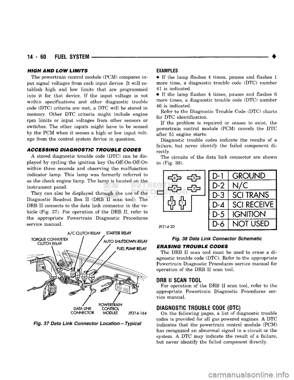
DRB II connects to the data link connector in the ve
hicle (Fig. 37). For operation of the DRB II, refer to
the appropriate Powertrain Diagnostic Procedures service manual.
TORQUE CONVERTER
CLUTCH RELAY
A/C
CLUTCH RELAY
.
STARTER RELAY
AUTO
SHUTDOWN RELAY FUEL PUMP RELAY POWERTRAIN
DATA LINK CONTROL
CONNECTOR MODULE
J9314-164
Fig.
37
Data
Link
Connector
Location—Typical
EXAMPLES
• If the lamp flashes 4 times, pauses and flashes 1
more time, a diagnostic trouble code (DTC) number
41 is indicated.
• If the lamp flashes 4 times, pauses and flashes 6
more times, a diagnostic trouble code (DTC) number
46 is indicated. Refer to the Diagnostic Trouble Code (DTC) charts
for DTC identification. If the problem is repaired or ceases to exist, the
powertrain control module (PCM) cancels the DTC after 51 engine starts.
Diagnostic trouble codes indicate the results of a
failure, but never identify the failed component di
rectly. The circuits of the data link connector are shown
in (Fig. 38).
J9214-20
D-1
GROUND
D-2 Im/c
D-3
SCI
TRANS
D-4
SCI
RECEIVE
D-5
IGNITION
D-6
NOT
USED
Fig.
38
Data
Link
Connector
Schematic
ERASING TROUBLE CODES The DRB II scan tool must be used to erase a di
agnostic trouble code (DTC). Refer to the appropriate
Powertrain Diagnostic Procedures service manual for operation of the DRB II scan tool.
DRB
II
SCAN
TOOL
For operation of the DRB II scan tool, refer to the
appropriate Powertrain Diagnostic Procedures ser
vice manual.
DIAGNOSTIC TROUBLE CODE
(DTC) On the following pages, a list of diagnostic trouble
codes is provided for all gas powered engines. A DTC indicates that the powertrain control module (PCM)
has recognized an abnormal signal in a circuit or the system. A DTC may indicate the result of a failure,
but never identify the failed component directly.
Page 901 of 1502
14 - 82
FUEL 'SYSTEM
—. — ~—— — «
INTAKE HEATER CYCLE CHART
Intake
featperafwre
Preheat
Cycle
Time
Ignition
l£ey ON
Engine
Not
Running
Pestheat
Cycle
Ignition
Key ON
Snglne Running
Above
15
°C
(59
°F)
0 Seconds
No
-8°C(18°F)to
15°C (59
°F)
10
Seconds
Yes
-17°C(1
°F)
-9
°C(]6°F)
15
Seconds
Yes
«2d°C(-15°F)
to-18°C(0
°F) 17.5
Seconds
Yes
Below-26
°C (-15
*F)
20 Seconds
Yes
J9114-239
AUTO SHUT DOWN (ASD) RELAY-PCM OUTPUT
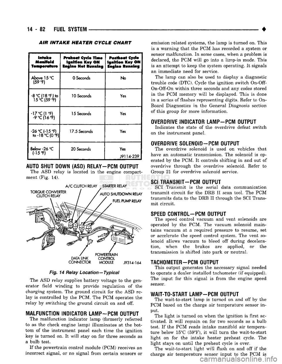
The ASD relay is located in the engine compart
ment (Fig. 14).
TORQUE CONVERTER
CLUTCH RELAY A/C CLUTCH RELAY STARTER RELAY
AUTO SHUTDOWN RELAY FUEL PUMP RELAY DATA LINK
CONNECTOR
POWERTRAIN
CONTROL MODULE
J9314-164
Fig.
14 Relay Location—Typical The ASD relay supplies battery voltage to the gen
erator field winding to provide regulation of the
charging system. The ground circuit for the ASD re
lay is controlled by the PCM. The PCM operates the
relay by switching the ground circuit on and off.
MALFUNCTION INDICATOR LAMP-PCM OUTPUT
The malfunction indicator lamp (formerly referred
to as the check engine lamp) illuminates at the bot
tom of the instrument panel each time the ignition
key is turned on. It will stay on for three seconds as
a bulb test. If the powertrain control module (PCM) receives an
incorrect signal, or no signal from certain sensors or emission related systems, the lamp is turned on. This
is a warning that the PCM has recorded a system or
sensor malfunction. In some cases, when a problem is
declared, the PCM will go into a limp-in mode. This is an attempt to keep the system operating. It signals
an immediate need for service.
The lamp can also be used to display a diagnostic
trouble code (DTC). Cycle the ignition switch
On-Off-
On-Off-On within three seconds and any codes stored
in the PCM memory will be displayed. This is done
in a series of flashes representing digits. Refer to On-
Board Diagnostics in the General Diagnosis section
of this group for more information.
OVERDRIVE
INDICATOR LAMP-PCM OUTPUT
Indicates the state of the overdrive defeat switch
on the instrument panel.
OVERDRIVE
S0LEN0ID-PCM OUTPUT
The overdrive solenoid is used on vehicles that
have an automatic transmission. The solenoid is op erated by the PCM. It controls shifting in and out of
overdrive through the overdrive solenoid. Refer to Group 21 for overdrive solenoid service.
SCI
TRANSMIT—PCM OUTPUT
SCI Transmit is the serial data communication
transmit circuit for the DRB II scan tool. The PCM
transmits data to the DRB II through the SCI Trans
mit circuit.
SPEED
C0NTR0L-PCM OUTPUT
The speed control vacuum and vent solenoids are
operated by the PCM. The vacuum solenoid main
tains vacuum at a required pressure to resume, set or accelerate the speed control system. The vent so
lenoid allows vacuum to bleed off during decelera
tion, when the brakes are applied, or the
transmission is shifted into park or neutral.
TACHOMETER-PCM
OUTPUT
This output generates the necessary signal needed
to operate a dealer installed tachometer (if equipped).
The input for this signal is from the engine speed sensor.
WAIT-TO-START LAMP-PCM OUTPUT
The wait-to-start lamp is turned on and off by the
PCM based on the charge air temperature sensor in
put. The light is turned on when the ignition is first ac
tivated. It will remain on for two seconds as a bulb
test. If the PCM reads intake manifold air tempera
ture below 15°C (59°F), it will turn the wait-to-start light on for the intake heater preheat cycle. The
light stays on until the preheat cycle is over. The wait-to-start light will flash on and off if the
charge air temperature sensor input to the PCM is
Page 913 of 1502
14
- 94
FUEL
SYSTEM
•
THROTTLE POSITION
SENSOR
TEST
CAUTION;
Before checking
the
TPS,
the
throttle
linkage must
be
checked
for
correct
adjustment.
The
throttle
lever must
contact
the low idle
speed screw.
The
throttle
lever must reach breakover when
the
throttle
is
wide
open. Refer
to the
Accelerator Pedal and
Throttle
Cable section
of
Group
14,
Fuel Systems.
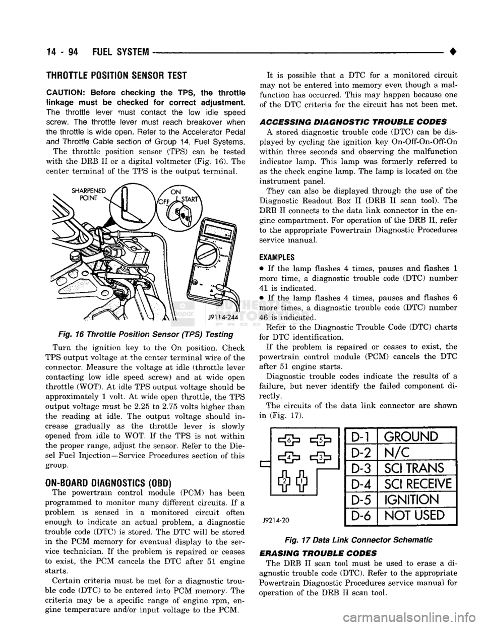
The throttle position sensor (TPS) can be tested
with the DRB II or a digital voltmeter (Fig. 16). The center terminal of the TPS is the output terminal.
J9114-244
Fig.
16
Throttle
Position
Sensor
(TPS) Testing
Turn the ignition key to the On position. Check
TPS output voltage at the center terminal wire of the connector. Measure the voltage at idle (throttle lever contacting low idle speed screw) and at wide open
throttle
(WOT).
At idle TPS output voltage should be approximately 1 volt. At wide open throttle, the TPS
output voltage must be 2.25 to 2.75 volts higher than
the reading at idle. The output voltage should in
crease gradually as the throttle lever is slowly
opened from idle to WOT. If the TPS is not within
the proper range, adjust the sensor. Refer to the Die sel Fuel Injection—Service Procedures section of this
group.
ON-BOARD
DIAGNOSTICS
(OBD) The powertrain control module (PCM) has been
programmed to monitor many different circuits. If a
problem is sensed in a monitored circuit often enough to indicate an actual problem, a diagnostic
trouble code (DTC) is stored. The DTC will be stored in the PCM memory for eventual display to the ser
vice technician. If the problem is repaired or ceases
to exist, the PCM cancels the DTC after 51 engine
starts.
Certain criteria must be met for a diagnostic trou
ble code (DTC) to be entered into PCM memory. The criteria may be a specific range of engine rpm, engine temperature and/or input voltage to the PCM. It is possible that a DTC for a monitored circuit
may not be entered into memory even though a mal
function has occurred. This may happen because one of the DTC criteria for the circuit has not been met.
ACCESSING DIAGNOSTIC TROUBLE CODES A stored diagnostic trouble code (DTC) can be dis
played by cycling the ignition key On-Off-On-Off-On
within three seconds and observing the malfunction indicator lamp. This lamp was formerly referred to
as the check engine lamp. The lamp is located on the
instrument panel.
They can also be displayed through the use of the
Diagnostic Readout Box II (DRB II scan tool). The
DRB II connects to the data link connector in the en
gine compartment. For operation of the DRB II, refer
to the appropriate Powertrain Diagnostic Procedures service manual.
EXAMPLES
• If the lamp flashes 4 times, pauses and flashes 1
more time, a diagnostic trouble code (DTC) number
41 is indicated.
• If the lamp flashes 4 times, pauses and flashes 6
more times, a diagnostic trouble code (DTC) number 46 is indicated. Refet* to the Diagnostic Trouble Code (DTC) charts
for DTC identification. If the problem is repaired or ceases to exist, the
powertrain control module (PCM) cancels the DTC after 51 engine starts.
Diagnostic trouble codes indicate the results of a
failure, but never identify the failed component di
rectly.
The circuits of the data link connector are shown
in (Fig. 17).
J9214-20
D-1
1
GROUND
D-2
N/C
D-3
SCI
TRANS
D-4
SCI
RECEIVE
D-5 IGNITION
D-6
NOT USED
Fig.
17
Data
Link
Connector
Schematic
ERASING TROUBLE CODES The DRB II scan tool must be used to erase a di
agnostic trouble code (DTC). Refer to the appropriate
Powertrain Diagnostic Procedures service manual for
operation of the DRB II scan tool.
Page 914 of 1502
•
FUEL SYSTEM
14 - 95
DRB
II
SCAN
TOOL
For operation
of the DRB II
scan tool, refer
to the
appropriate Powertrain Diagnostic Procedures ser
vice manual.
DIAGNOSTIC TROUBLE CODE (DTC)
On
the
following pages,
a
list
of
diagnostic trouble
codes
is
provided
for the
diesel engine.
A DTC
indi cates that
the
powertrain control module
(PCM) has
recognized
an
abnormal signal
in a
circuit
or the
sys
tem.
A DTC may
indicate
the
result
of a
failure,
but
never identify
the
failed component directly.
SYSTEM SCHEMATICS—5.9L DIESEL ENGINE
Refer
to the
following system schematic
for the
5.9L diesel engine.