1993 DODGE TRUCK oil dipstick
[x] Cancel search: oil dipstickPage 33 of 1502

0 - 14
LUBRICATION
AND
MAINTENANCE
•
ENGINE
MAINTENANCE
INDEX
page
Air
Injection
Systems/Air Pump
. 17
Air-Conditioner
Compressor
21
Battery
19
Cooling System
15
Crankcase
Ventilation
System
17
Diesel Engine
Air Filter
Canister
17
Drive Belts
20
Engine
Air
Cleaner
Filter
Element
16
Engine Break-In
14
Engine
Oil 14
Engine
Oil
Change
and Filter
Replacement
15
Exhaust Gas
Recirculation
(EGR) System
...... 19
page
Exhaust
Manifold
Heat
Control
Valve
. 17
Exhaust System
, 21
Fuel System
18
Hoses
and
Fittings
16
Ignition
Cables,
Distributor
Cap and
Rotor
...... 19
Ignition
Timing
. 19
Oxygen
(02)
Sensor
19
Rubber/Plastic Components
20
Spark Plugs
. 19
Throttle
Control
Linkage
18
Vacuum Operated, Emission
Control
Components
19
ENGINE BREAK-IN
After first starting a new engine, allow it to idle
for 15 seconds before shifting into a drive gear. Also:
• Drive the vehicle at varying speeds less than 88
km/h (55 mph) for the first 480 km (300 miles).
• Avoid fast acceleration and sudden stops.
• Do not drive at full-throttle for extended periods of
time
• Do not drive at constant speeds
• Do not idle the engine excessively A special break-in engine oil is not required. The
original engine oil installed is a high quality lubri
cant. New engines tend to consume more fuel and oil un
til after the break-in period has ended.
ENGINE
OIL SPECIFICATIONS
API SERWICE
GRADE
Use an engine oil that conforms to API Service
Grade S5 SG/CD or SG/CE. MOPAR®provides engine
oils that conform to all of these service grades.
SULFATED ASH—DIESEL ENGINES
Oils that contain an excessive amount of sulfated
ash can cause deposits to develop on Diesel engine
valves. These deposits can result in valve wear.
SAE
WISC0SITY
An SAE viscosity grade is used to specify the vis
cosity of engine oil. SAE 30 specifies a single viscos
ity engine oil.
Engine oils also have multiple viscosities. 10W-30
<
5W-30
1
1 1
F
-20 0 10 20 32 60 80 100
C
-29 -18 -12 -7 0 16 27 38
ANTICIPATED
TEMPERATURE RANGE BEFORE
NEXT
OIL
CHANGE
J9000-39
Fig.
1 Temperature/Engine Oil Viscosity—Gasoline
Engines
-12°C
-18°C 10°F
0°F- 15W-40
-23°c(^-10eF
I
10W-30
WITH
WITHOUT
BLOCK HEATER
BLOCK
SYNTHETIC
OIL
HEATER
10W-30 5W-30
J9100-29
Fig.
2 Temperature/Engine Oil Viscosity—Diesel
Engines
ENERGY
G0NSERWING
OIL
An Energy Conserving type oil is recommended for
gasoline engines. They are designated as either EN
ERGY CONSERVING or ENERGY CONSERVING
II.
OIL
LEVEL
INDICATOR (DIPSTICK)
GASOLINE ENGINES
The engine oil indicator is located at the right
front of the engine.
Page 34 of 1502

•
LUBRICATION
AND
MAINTENANCE
0 - 15
DIESEL
ENGINES
The Diesel engine oil level indicator is located at
the left center of the engine, above the
fuel
injection
pump (Fig. 3).
Fig.
3
Diesel
Engine
Oil
Dipstick
ACCEPTABLE
OIL
LEVEL
To maintain proper lubrication of an engine, the
engine oil must be maintained at an acceptable level.
For gasoline engines, the acceptable levels are indi cated between the ADD and
FULL
marks on oil
dip
stick. For Diesel engines, the acceptable levels are
indicated between the L (low) and H
(high) marks
on
oil dipstick. The oil level should be checked periodically. The
vehicle should be on a level surface. Wait for
five
minutes after stopping the engine. For gasoline en
gines,
add oil only when the level indicated on the
dipstick is at or below the ADD mark. For Diesel en
gines,
add oil only when the level indicated on the
dipstick is between the L and H marks.
Never oper
ate a Diesel
engine when
the oil
level
is below
the L mark. The distance between the L and H
marks represents 1.9L (2 Qts) engine oil.
CAUTION:
Do not
overfill
an
engine crankcase
with
oil. This
will
cause
oil
aeration
and
result
in a de
crease
in the
engine
oil
pressure.
ENGINE
OIL
CHANGE AND FILTER REPLACEMENT
WARNING: PROTECTIVE CLOTHING
AND
GLOVES SHOULD
BE
WORN. EXPOSED SKIN SHOULD
BE
WASHED
WITH
SOAP
AND
WATER
TO
REMOVE
USED
ENGINE
OIL.
DO NOT
USE
GASOLINE, THIN
NER,
OR
SOLVENTS
TO
REMOVE ENGINE
OIL
FROM
SKIN.
DO NOT
POLLUTE. DISPOSE
OF
USED
ENGINE
OIL
PROPERLY.
ENGINE
OIL
FILTER
All engines are equipped with a throw-away type
oil filter. The same type of filter is recommended
when the filter is changed.
OIL CHANGE
AND
FILTER
REPLACEMENT
Bring engine up to normal operating temperature.
A more complete drainage of oil will result.
(1) Remove the drain hole plug and drain the en
gine oil from the crankcase.
(2) Install the drain hole plug with a replacement
gasket. For gasoline engines, the oil filter should be
replaced during every second engine oil change.
For Diesel engines, the oil filter should be re
placed during every engine oil change.
(3) Rotate the oil filter counterclockwise to remove
it.
(4) Clean the engine cylinder block oil filter boss. (5) Apply a light coat of new engine oil to the rub
ber seal on the oil filter.
(6) Install and hand tighten the oil filter 1/2 to 3/4
of a turn clockwise. (7) Add new engine oil at the fill hole location on
top of the engine cylinder head cover. Wipe off any spilled oil.
(8) Observe the oil level on the dipstick.
CAUTION:
Do not
overfill
the
engine crankcase
with
oil.
(9)
Start the engine. Observe the oil pressure
gauge or warning lamp (as applicable). If the oil
pressure does not increase, stop the engine immedi ately. Check oil level.
COOLING SYSTEM
WARNING:
USE
EXTREME CAUTION WHEN
THE
ENGINE
IS
OPERATING.
DO NOT PUT
YOUR
HANDS NEAR
THE
DRIVE BELT(S), PULLEYS
OR
FAN BLADE.
DO NOT
STAND
IN A
DIRECT LINE
WITH
THE FAN
BLADE.
INSPECTION SCHEDULE
Determine the coolant level. Inspect the cooling
system hoses/clamps after each service interval has
elapsed.
COOLANT LEVEL
It is recommended that the engine coolant level be
inspected at least once a month during periods of hot
weather.
With the engine at normal operating temperature,
check the coolant level in the coolant reserve tank.
The coolant level must be at least above the ADD mark. Add coolant to the coolant reserve tank only.
Page 42 of 1502
•
LUBRICATION
AND
MAINTENANCE
0 - 23 GEAR SHIFTER BOOTS
Inspect the shifter boots periodically for stone and
heat damage. Replace, if necessary.
SEVERE DRIVING CONDITIONS The interval between the transmission drain and
refill maintenance should be decreased to:
• NV4500 manual transmission—every 29 000 km (18,000 miles)
• Automatic transmission—every 19 000 km (12,000
miles)
A severe driving condition includes:
• Extended operation with heavy cargo loads
• Driving in deep mud or snow
• Off-road operation (4WD)
• Trailer towing
• Operation as a commercial vehicle
• Snow plowing
MANUAL TRANSMISSIONS
INSPECTION/LUBE
OIL
LEVEL
The transmission should be checked for leaks when
other service is necessary under the vehicle. To check
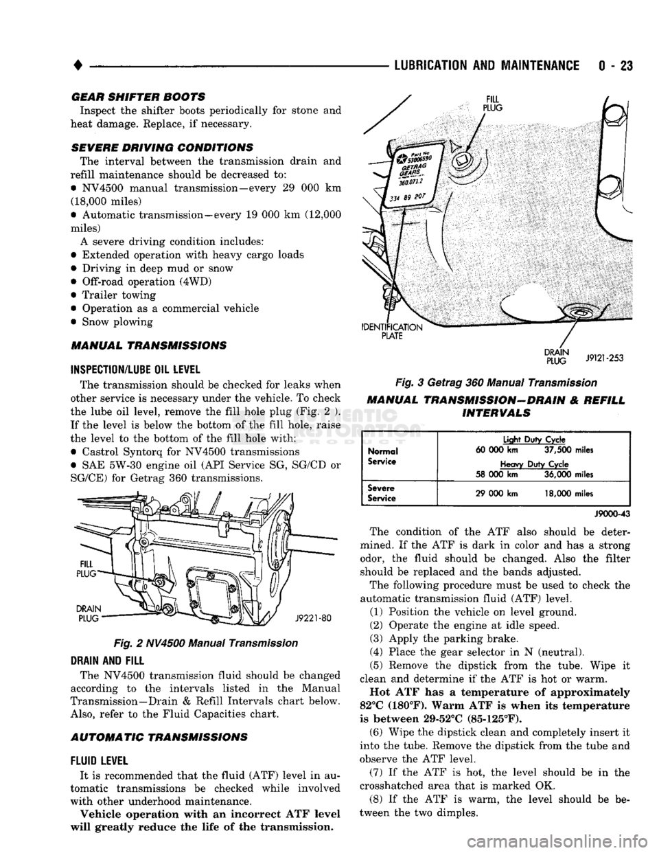
the lube oil level, remove the fill hole plug (Fig. 2 ). If the level is below the bottom of the fill hole, raise
the level to the bottom of the fill hole with:
• Castrol Syntorq for NV4500 transmissions
• SAE 5W-30 engine oil (API Service SG, SG/CD or
SG/CE) for Getrag 360 transmissions.
Fig.
2 NV4500 Manual
Transmission
DRAIN
AND
FILL
The NV4500 transmission fluid should be changed
according to the intervals listed in the Manual
Transmission—Drain & Refill Intervals chart below.
Also,
refer to the Fluid Capacities chart.
AUTOMATIC TRANSMISSIONS
FLUID
LEWEL
It is recommended that the fluid (ATF) level in au
tomatic transmissions be checked while involved
with other underhood maintenance.
Vehicle operation with an incorrect ATF level
will greatly reduce the life of the transmission.
Fig.
3 Getrag 360 Manual
Transmission
MANUAL TRANSMISSION-DRAIN & REFILL INTERVALS
Normal
Service
Light
Duty
Cycle
60 000
km
37,500
miles
Heavy
Duty
Cycle
58 000
km
36,000
miles
Severe
Service
29 000
km
18,000
miles
J9000-43
The condition of the ATF also should be deter
mined. If the ATF is dark in color and has a strong odor, the fluid should be changed. Also the filter should be replaced and the bands adjusted.
The following procedure must be used to check the
automatic transmission fluid (ATF) level.
(1) Position the vehicle on level ground.
(2) Operate the engine at idle speed.
(3) Apply the parking brake.
(4) Place the gear selector in N (neutral).
(5) Remove the dipstick from the tube. Wipe it
clean and determine if the ATF is hot or warm.
Hot ATF has a temperature of approximately
82°C (180°F). Warm ATF is when its temperature
is between 29-52°C (85-125°F). (6) Wipe the dipstick clean and completely insert it
into the tube. Remove the dipstick from the tube and
observe the ATF level.
(7) If the ATF is hot, the level should be in the
crosshatched area that is marked OK.
(8) If the ATF is warm, the level should be be
tween the two dimples.
Page 43 of 1502
0
- 24
LUBRICATION
AND
MAINTENANCE
•
CAUTION:
Do not
overfill
the
transmission.
(9) Adjust
the
level
of the ATF
accordingly.
It
is
important
to use the
correct fluid
in an
automatic transmission. MOPAR®ATF PLUS
(ATF Type
7176)
should
be
used. Dexron®
II
ATF
can be
used
if the
recommended fluid
is not
available,
(10) Insert
the
dipstick into
the
tube.
DRAIN, FILTER CHANGE, BAND ADJUSTMENT AND REFILL
The chart below lists
the
intervals
at
which
the
transmission should
be
serviced. Also, refer
to the
Fluid Capacities chart
for
fill capacity.
AUTOMATIC TRANSMISSION SERVICE
IN-
TERVALS
Normal
Usage
Light
Duty
Cycle
60 000
km
37,500
miles
Heavy
Duty
Cycle
38
000 km 24,000
miles
Severe
Usage
19 000 km 12,000
miles
J9100-19
It
is
very important
to use the
correct fluid
in
an automatic transmission. MOPAR®ATF PLUS
(ATF Type
7176)
should
be
used.
An
equivalent
Dexron®
II ATF
could
be
used only
if the
recom
mended fluid
is not
available.
The torque converter does
not
have
a
drain plug.
No attempt should
be
made
to
drain
the
converter.
Refer
to
Group
21
—Transmissions
for
transmission
drain
and
refill procedures.
TRANSFER
CASE
(4WD
VEHICLES)
INSPECTION The NP205
and
NP241 transfer cases fluid level
should
be
checked whenever maintenance
is
neces
sary under
the
vehicle.
FLUID
LEVEL
The vehicle must
be
level when
the
fluid level
is checked.
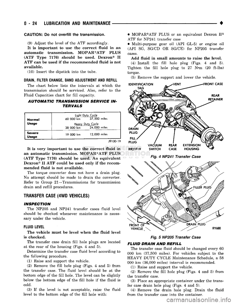
The transfer case drain fill hole plugs
are
located
at
the
rear
of the
housing (Figs.
4 and 5).
Determine
the
transfer case fluid level according
to
the following procedure.
(1) Raise
and
support
the
vehicle.
(2) Remove
the
fill hole plug (Figs.
4 and 5)
from
the transfer case.
The
fluid level should
be at the
bottom edge
of the
fill hole.
The
level
can be
slightly
below
the
bottom edge
of the
fill hole
if the
fluid
is
cold.
(3)
If the
level
is not
acceptable, raise
the
fluid
level
to the
bottom edge
of the
fill hole with: • MOPAR®ATF PLUS
or an
equivalent Dexron
II®
ATF
for
NP241 transfer case
• Multi-purpose gear
oil (API GL-5) or
engine
oil
(API
SG,
SG/CD
OR
SG/CE)
for
NP205 transfer
cases.
Add fluid
in
small amounts
to
raise
the
level. (4) Install
the
fill hole plug (Figs.
4 and 5).
Tighten
the
fill hole plug
to 27 N-m (20
ft-lbs) torque.
(5) Remove
the
support
and
lower
the
vehicle.
Fig.
4
HP241 Transfer
Case
Fig.
5
NP205 Transfer
Case
FLUID DRAIN
AND
REFILL The transfer case fluid should
be
changed every
60
000
km
(37,500 miles).
For
vehicles subject
to the
HEAVY DUTY CYCLE Maintenance Schedule,
a 58
000
km
(36,000 miles) interval
is
recommended.
(1) Raise
and
support
the
vehicle.
(2) Remove
the
fill hole plug (Figs.
4 and 5)
from
the transfer case. (3) Place
an
appropriate container under
the
trans
fer case drain hole plug (Figs.
4 and 5).
(4) Remove
the
drain hole plug. Drain
the
fluid
from
the
transfer case into
the
container.
Page 291 of 1502
7 - 20
COOLING
SYSTEM
•
HOSE
CLAMP
HOSE
J9207-36
Fig.
16
Hose
Clamp
Tool
WITH AIR
CONDITIONING
(A/C)
REMOVAL
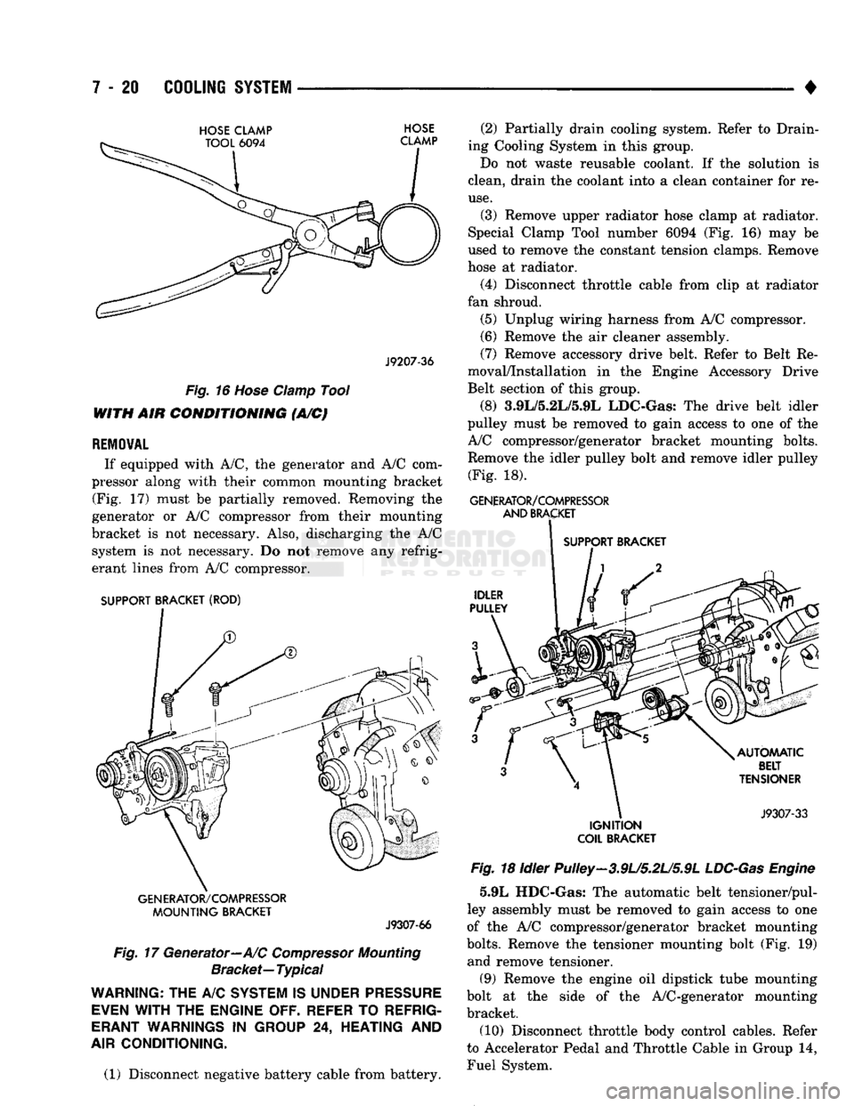
If equipped with A/C, the generator and A/C com
pressor along with their common mounting bracket (Fig. 17) must be partially removed. Removing the
generator or A/C compressor from their mounting
bracket is not necessary. Also, discharging the A/C system is not necessary. Do not remove any refrig
erant lines from A/C compressor.
SUPPORT BRACKET (ROD)
GENERATOR/COMPRESSOR
MOUNTING
BRACKET
J9307-66
Fig.
17 Generator—A/C
Compressor
Mounting
Bracket—
Typical
WARNING;
THE A/C
SYSTEM
IS
UNDER
PRESSURE
EVEN
WITH
THE
ENGINE OFF. REFER
TO
REFRIG
ERANT
WARNINGS
IN
GROUP
24,
HEATING
AND
AIR
CONDITIONING.
(1) Disconnect negative battery cable from battery. (2) Partially drain cooling system. Refer to Drain
ing Cooling System in this group.
Do not waste reusable coolant. If the solution is
clean, drain the coolant into a clean container for re
use.
(3) Remove upper radiator hose clamp at radiator.
Special Clamp Tool number 6094 (Fig. 16) may be
used to remove the constant tension clamps. Remove
hose at radiator.
(4) Disconnect throttle cable from clip at radiator
fan shroud. (5) Unplug wiring harness from A/C compressor.
(6) Remove the air cleaner assembly.
(7) Remove accessory drive belt. Refer to Belt Re
moval/Installation in the Engine Accessory Drive
Belt section of this group.
(8) 3.9L/5.2L/5.9L LDC-Gas: The drive belt idler
pulley must be removed to gain access to one of the
A/C compressor/generator bracket mounting bolts. Remove the idler pulley bolt and remove idler pulley (Fig. 18).
GENERATOR/COMPRESSOR
AND
BRACKET
SUPPORT BRACKET
IGNITION
COIL
BRACKET
Fig.
18 Idler Pulley-3.9U5.2U5.9L
LDC-Gas
Engine
5.9L HDC-Gas: The automatic belt tensioner/pul-
ley assembly must be removed to gain access to one
of the A/C compressor/generator bracket mounting
bolts.
Remove the tensioner mounting bolt (Fig. 19) and remove tensioner.
(9) Remove the engine oil dipstick tube mounting
bolt at the side of the A/C-generator mounting
bracket.
(10) Disconnect throttle body control cables. Refer
to Accelerator Pedal and Throttle Cable in Group 14,
Fuel System.
Page 293 of 1502
7 - 22
COOLING
SYSTEM
•
Fig.
23 Bracket
Bolts—5.9L
HDC-Gas Engine
(2) Install bypass hose to engine.
(3) Secure both hose clamps.
(4) Install generator-A/C mounting bracket assem
bly to engine. Tighten bolts (number 1 and 2 Fig. 17)
to 54 Nnn (40 ft. lbs.) torque. Tighten bracket mount ing bolts (Figs. 22 or 23) to 40 N-m (30 ft. lbs.)
torque.
(5) Install a new O-ring to the heater hose coolant
return tube (Figs. 20 or 21). Coat the new O-ring
with antifreeze before installation. (6) Install coolant return tube and its mounting
bolt to engine (Figs. 20 or 21). (7) Connect throttle body control cables.
(8) Install oil dipstick mounting bolt.
(9) 3.9L/5.2L/5.9L LDC-Gas: Install idler pulley.
Tighten bolt to 54 Nnn (40 ft. lbs.) torque. 5.9L HDC-Gas: Install automatic belt tensioner
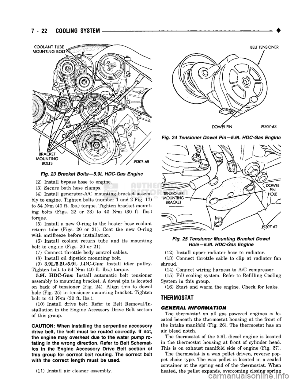
assembly to mounting bracket. A dowel pin is located
on back of tensioner (Fig. 24). Align this to dowel
hole (Fig. 25) in tensioner mounting bracket. Tighten
bolt to 41 N-m (30 ft. lbs.). (10) Install drive belt. Refer to Belt Removal/In
stallation in the Engine Accessory Drive Belt section
of this group.
CAUTION:
When installing
the
serpentine
accessory
drive belt,
the
belt must
be
routed correctly.
If not,
the engine
may
overheat
due to the
water pump
ro
tating
in the
wrong direction. Refer
to
Belt Schemat
ics
in the
Engine
Accessory
Drive Belt section
of
this
group
for
correct belt routing.
The
correct belt
with the
correct length must
be
used.
(11) Install air cleaner assembly.
BELT TENSIONER
DOWEL PIN
J9307-63
Fig.
24 Tensioner
Dowel
Pin—5.9L
HDC-Gas Engine Fig.
25 Tensioner
Mounting
Bracket
Dowel
Hote—5.9L
HDC-Gas Engine
(12) Install upper radiator hose to radiator.
(13) Connect throttle cable to clip at radiator fan
shroud.
(14) Connect wiring harness to A/C compressor. (15) Fill cooling system. Refer to Refilling Cooling
System in this group.
(16) Start and warm the engine. Check for leaks.
THERMOSTAT
GENERAL
INFORMATION
The thermostat on all gas powered engines is lo
cated beneath the thermostat housing at the front of
the intake manifold (Fig. 26). The thermostat has an air bleed notch.
The thermostat of the 5.9L diesel engine is located
in the thermostat housing at front of cylinder head.
This is on exhaust manifold side of engine (Fig. 27). The thermostat is a wax pellet driven, reverse pop
pet choke type. The wax pellet is located in a sealed container at the spring end of the thermostat. When
heated, the pellet expands, overcoming closing spring
Page 301 of 1502

7 - 30
COOLING
SYSTEM
•
COOLING
SYSTEM
Fig.
39
Pressure
Testing
Cooling
System—Typical bulges while testing, replace as necessary. Observe
gauge pointer and determine condition of cooling sys
tem according to following criteria:
Holds Steady: If pointer remains steady for two
minutes, serious coolant leaks are not present in sys
tem. However, there could be an internal leak that does not appear with normal system test pressure. If
it is certain that coolant is being lost and leaks can
not be detected, inspect for interior leakage or per
form Internal Leakage Test.
Drops Slowly: Indicates a small leak or seepage is
occurring. Examine all connections for seepage or
slight leakage with a flashlight. Inspect radiator,
hoses,
gasket edges and heater. Seal small leak holes
with a Sealer Lubricant (or equivalent). Repair leak
holes and inspect system again with pressure ap
plied.
Drops Quickly: Indicates that serious leakage is
occurring. Examine system for external leakage. If
leaks are not visible, inspect for internal leakage.
Large radiator leak holes should be repaired by a
reputable radiator repair shop.
INTERNAL LEAKAGE INSPECTION Remove engine oil pan drain plug and drain a
small amount of engine oil. If coolant is present in
the pan, it will drain first because it is heavier than
oil.
An alternative method is to operate engine for a
short period to churn the oil. After this is done, re
move engine dipstick and inspect for water globules.
Also inspect transmission dipstick for water globules and transmission fluid cooler for leakage.
WARNING:
WITH
PRESSURE TESTER TOOL
7700
INSTALLED
ON
RADIATOR,
DO
NOT ALLOW
PRES
SURE
TO
EXCEED
110 KPA (20
PSI). PRESSURE
WILL
BUILD
UP
QUICKLY
IF A
COMBUSTION LEAK
IS
PRESENT.
TO
RELEASE
PRESSURE,
ROCK
TESTER
FROM SIDE
TO
SIDE. WHEN REMOVING
TESTER,
DO NOT
TURN TESTER MORE THAN
1/2
TURN
IF
SYSTEM
IS
UNDER
PRESSURE.
Operate engine without pressure cap on radiator
until thermostat opens. Attach a Pressure Tester to
filler neck. If pressure builds up quickly it indicates a combustion leak exists. This is usually the result of
a cylinder head gasket leak or crack in engine. Re
pair as necessary.
If there is not an immediate pressure increase,
pump the Pressure Tester. Do this until indicated
pressure is within system range of 110 kPa (16 psi). Fluctuation of gauge pointer indicates compression or
combustion leakage into cooling system.
Because the vehicle is equipped with a catalytic
converter, do not remove spark plug cables or short
out cylinders (non-diesel engines) to isolate compres
sion leak.
If the needle on dial of pressure tester does not
fluctuate, race engine a few times to check for an ab normal amount of coolant or steam. This would be
emitting from exhaust pipe. Coolant or steam from
exhaust pipe may indicate a faulty cylinder head
gasket, cracked engine cylinder block or cylinder
head. A convenient check for exhaust gas leakage into
cooling system is provided by a commercially avail able Block Leak Check tool. Follow manufacturers
instructions when using this product.
COMBUSTION LEAKAGE TEST-WITHOUT
PRESSURE TESTER DO NOT WASTE reusable coolant. If solution is
clean, drain coolant into a clean container for reuse.
WARNING:
DO NOT
REMOVE CYLINDER BLOCK DRAIN PLUGS
OR
LOOSEN RADIATOR DRAIN-
COCK
WITH
SYSTEM
HOT AND
UNDER PRES
SURE.
SERIOUS BURNS FROM COOLANT
CAN
OCCUR.
Drain sufficient coolant to allow thermostat re
moval. Refer to Thermostat Replacement. Disconnect
water pump drive belt. Add coolant to radiator to bring level to within 6.3
mm (1/4 in) of top of thermostat housing.
CAUTION:
Avoid
overheating.
Do not
operate
en
gine
for an
excessive
period
of
time.
Open
drain-
cock
immediately
after
test
to
eliminate
boil
over.
Start engine and accelerate rapidly three times, to
approximately 3000 rpm while observing coolant. If
internal engine combustion gases% are leaking into
cooling system, bubbles will appear in coolant. If
bubbles do not appear, internal combustion gas leak age is not present.
COOLANT
RESERVE/0WERFL0W
SYSTEM
The coolant reserve/overflow system (Fig. 40 or 41)
works in conjunction with the radiator pressure cap.
Page 620 of 1502
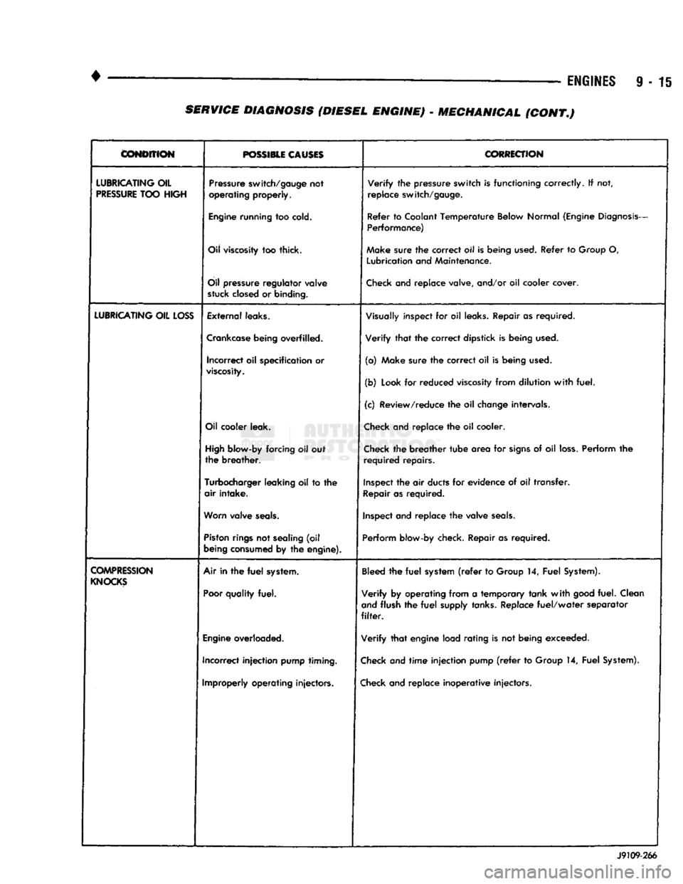
•
• —
ENGINES
9 - 15
CONDITION
POSSIBLE CAUSES
CORRECTION
LUBRICATING
OIL
PRESSURE
TOO
HIGH
Pressure
switch/gauge
not
operating
properly.
Verify
the
pressure
switch
is
functioning
correctly.
If not,
replace
switch/gauge.
Engine
running
too
cold.
Refer
to
Coolant
Temperature
Below
Normal
(Engine
Diagnosis-
Performance)
Oil
viscosity
too thick. Make
sure
the
correct
oil Is
being
used.
Refer
to
Group
O,
Lubrication
and
Maintenance.
Oil
pressure
regulator
valve
stuck
closed
or
binding.
Check
and replace valve, and/or oil cooler cover.
LUBRICATING
OIL
LOSS
External
leaks.
Visually
inspect for oil
leaks.
Repair as required.
Crankcase
being
overfilled. Verify that the correct dipstick is being
used.
incorrect
oil specification or
viscosity.
(a) Make sure the correct oil is being
used.
(b)
Look
for reduced
viscosity
from dilution with fuel.
(c) Review/reduce the oil
change
intervals.
Oil
cooler
leak.
Check
and replace the oil cooler.
High
blow-by
forcing oil out
the breather.
Check
the breather tube area for
signs
of oil
loss.
Perform the
required repairs.
Turbocharger
leaking
oil to the
air intake.
Inspect
the air
ducts
for evidence of oil transfer.
Repair
as required.
Worn
valve
seals.
Inspect
and replace the valve
seals.
Piston
rings
not
sealing
(oil
being
consumed
by the
engine).
Perform
blow-by check. Repair as required.
COMPRESSION
KNOCKS
Air in the
fuel
system.
Poor
quality
fuel.
Bleed
the fuel
system
(refer
to
Group
14, Fuel
System).
Verify by operating from a temporary tank with
good
fuel. Clean
and
flush the fuel
supply
tanks.
Replace fuel/water separator
filter.
Engine
overloaded. Verify that engine load rating is not being exceeded.
Incorrect injection
pump
timing.
Check
and time injection pump
(refer
to
Group
14, Fuel
System).
Improperly
operating
injectors.
Check
and replace inoperative injectors. J9109-266 SERVICE DIAGNOSIS (DIESEL ENGINE) - MECHANICAL (CONT.)