1993 DODGE TRUCK oil dipstick
[x] Cancel search: oil dipstickPage 739 of 1502
9
- 134 5.9L
(DIESEL) ENGINE
• (4) Fill the engine with oil. Run the engine and
check for leaks.
(5) Stop the engine and check the oil level with the
dipstick.
CUP
PLUG
J9109-30
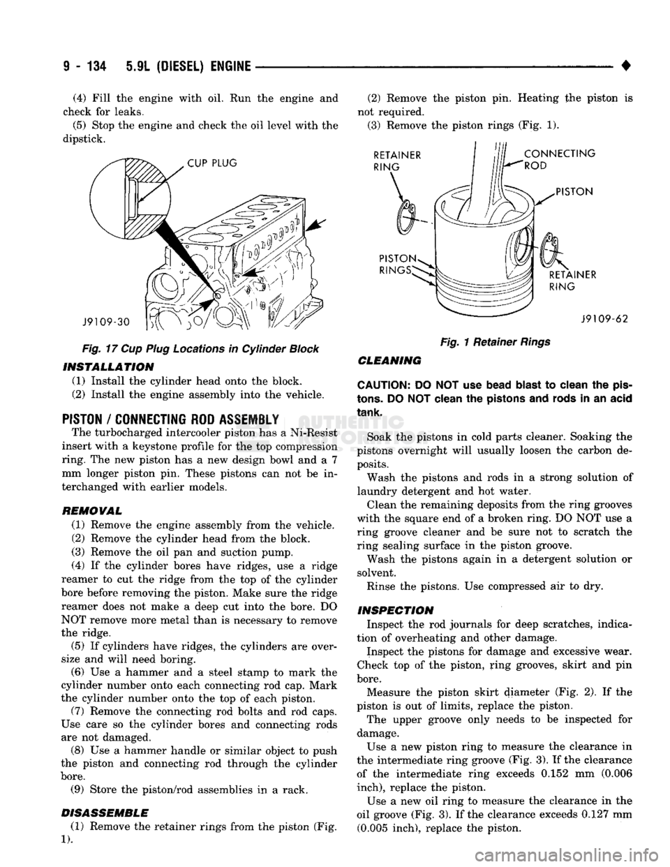
Fig.
17 Cup Plug Locations in Cylinder Block INSTALLATION
(1) Install the cylinder head onto the block.
(2) Install the engine assembly into the vehicle.
PISTON
/
CONNECTING ROD ASSEMBLY
The turbocharged intercooler piston has a Ni-Resist
insert with a keystone profile for the top compression
ring. The new piston has a new design bowl and a 7 mm longer piston pin. These pistons can not be in
terchanged with earlier models.
REMOVAL (1) Remove the engine assembly from the vehicle.
(2) Remove the cylinder head from the block.
(3) Remove the oil pan and suction pump.
(4) If the cylinder bores have ridges, use a ridge
reamer to cut the ridge from the top of the cylinder
bore before removing the piston. Make sure the ridge reamer does not make a deep cut into the bore. DO
NOT remove more metal than is necessary to remove
the ridge.
(5) If cylinders have ridges, the cylinders are over
size and will need boring. (6) Use a hammer and a steel stamp to mark the
cylinder number onto each connecting rod cap. Mark
the cylinder number onto the top of each piston. (7) Remove the connecting rod bolts and rod caps.
Use care so the cylinder bores and connecting rods
are not damaged. (8) Use a hammer handle or similar object to push
the piston and connecting rod through the cylinder
bore.
(9) Store the piston/rod assemblies in a rack.
DISASSEMBLE (1) Remove the retainer rings from the piston (Fig.
1).
(2) Remove the piston pin. Heating the piston is
not required. (3) Remove the piston rings (Fig. 1). RETAINER
RING
CONNECTING
ROD
PISTON
PISTON RIN RETAINER
RING J9109-62
Fig.
1 Retainer
Rings
CLEANING
CAUTION: DO NOT use bead
blast
to clean the
pis
tons.
DO
NOT
clean the pistons and rods in an acid
tank.
Soak the pistons in cold parts cleaner. Soaking the
pistons overnight will usually loosen the carbon de posits.
Wash the pistons and rods in a strong solution of
laundry detergent and hot water.
Clean the remaining deposits from the ring grooves
with the square end of a broken ring. DO NOT use a
ring groove cleaner and be sure not to scratch the
ring sealing surface in the piston groove.
Wash the pistons again in a detergent solution or
solvent.
Rinse the pistons. Use compressed air to dry.
INSPECTION Inspect the rod journals for deep scratches, indica
tion of overheating and other damage.
Inspect the pistons for damage and excessive wear.
Check top of the piston, ring grooves, skirt and pin
bore.
Measure the piston skirt diameter (Fig. 2). If the
piston is out of limits, replace the piston.
The upper groove only needs to be inspected for
damage.
Use a new piston ring to measure the clearance in
the intermediate ring groove (Fig. 3). If the clearance of the intermediate ring exceeds 0.152 mm (0.006
inch),
replace the piston.
Use a new oil ring to measure the clearance in the
oil groove (Fig. 3). If the clearance exceeds 0.127 mm (0.005 inch), replace the piston.
Page 751 of 1502
9
- 148 5.9L
(DIESEL) ENGINE
• Make sure the idler gear pin is installed in the lo
cating bore in the cylinder block. (2) Install the pump. Tighten the oil pump mount
ing bolts in two steps and in the sequence shown (Fig. 2).
• Step
1—Tighten
to 5 N«m (44 in. lbs.) torque.
• Step 2-Tighten to 24 N*m (18 ft. lbs.) torque. (3) The back plate on the pump seats against the
bottom of the bore in the cylinder block. When the
pump is correctly installed, the flange on the pump will not touch the cylinder block.
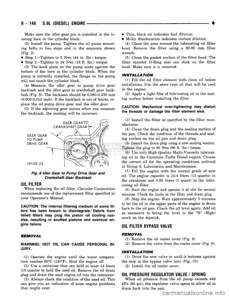
(4) Measure the idler gear to pump drive gear
backlash and the idler gear to crankshaft gear back lash (Fig. 8). The backlash should be 0.080-0.330 mm (0.003-0.013 inch). If the backlash is out of limits, re
place the oil pump drive gear and the idler gear.
(5) If the adjoining gear moves when you measure
the backlash, the reading will be incorrect.
Fig.
8
idler
Gear to
Pump
Drive Gear and Crankshaft Gear
Backlash
OIL FILTER
When replacing the oil filter, Chrysler Corporation
recommends use of the replacement filter specified in
your Operator's Manual.
CAUTION:
The
internal filtering medium
of
some
fil
ters
has
been known
to
disintegrate. Debris from
failed filters
may
plug
the
piston
oil
cooling noz
zles,
resulting
in
scuffed pistons
and
eventual
en
gine
failure.
REMOVAL
WARNING:
HOT OIL CAN
CAUSE PERSONAL
IN
JURY.
(1) Operate the engine until the water tempera
ture reaches 60°C (140°F). Shut the engine off.
(2) Use a container that can hold at least 14 liters
(15 quarts) to hold the used oil. Remove the oil drain
plug and drain the used engine oil into the container.
(3) Always check the condition of the used oil. This
can give you an indication of some engine problems
that might exist. • Thin, black oil indicates fuel dilution.
• Milky discoloration indicates coolant dilution.
(4) Clean the area around the lubricating oil filter
head. Remove the filter using a 90-95 mm filter
wrench.
(5) Clean the gasket surface of the filter head. The
filter canister O-Ring seal can stick on the filter
head. Make sure it is removed.
INSTALLATION (1) Fill the oil filter element with clean oil before
installation. Use the same type oil that will be used
in the engine.
(2) Apply a light film of lubricating oil to the seal
ing surface before installing the filter.
CAUTION:
Mechanical over-tightening
may
distort
the threads
or
damage
the filter
element seal.
(3) Install the filter as specified by the filter man
ufacturer. (4) Clean the drain plug and the sealing surface of
the pan. Check the condition of the threads and seal ing surface on the oil pan and drain plug.
(5) Install the drain plug using a new sealing washer.
Tighten the plug to 80 N-m (60 ft. lbs.) torque.
(6) Use only High-Quality Multi-Viscosity lubricat
ing oil in the Cummins Turbo Diesel engine. Choose
the correct oil for the operating conditions outlined in Group 0, Lubrication and Maintenance.
(7) Fill the enginfe with the correct grade of new
oil.
The engine capacity is i0.4 liters (11 quarts) in
the crankcase and 0.95 liters (1 quart) in the lubri cating oil filter. (8) Start the engine and operate it at idle for several
minutes. Check for leaks at the filter and drain plug.
(9) Stop the engine. Wait approximately 5 minutes
to let the oil in the upper parts of the engine to drain
back to the oil pan. Check the oil level again. Add oil as necessary to bring the level to the "H" (High)
mark on the dipstick.
OIL FILTER
BYPASS
VALWE
REMOVAL
(1) Remove the oil cooler cover (Fig. 9). (2) Remove the valve from the cooler cover (Fig. 9).
INSTALLATION (1) Drive the new valve in until it bottoms against
the step in the bypass valve bore (Fig. 10).
(2) Install the oil cooler cover.
OIL PRESSURE REGULATOR VALVE
/
SPRING
When oil pressure from the oil pump exceeds 448
kPa (65 psi), the regulator valve opens to allow oil to
drain back into the pan.
Page 1086 of 1502
•
AUTOMATIC TRANSiISSiOi-32RH/38RH/37RH/42RH/4eRH
21 - 81 AUTOMATIC TRANSMISSION DIAGNOSIS AND TESTING
INDEX
page
Air Testing Clutch
and
Band Operation
91
Analyzing
the
Road Test
87
Converter Housing Fluid Leak Diagnosis
.......
92
Converter
Stall
Test
90
Diagnosis
Charts
and
Hydraulic Flow Diagrams
. . 95
Fluid Contamination
86
Fluid Level
and
Condition
85
GENERAL
INFORMATION
The diagnosis
and
testing information
in
this sec
tion applies
to
three
and
four speed models alike.
Di
agnosis
and
test procedures apply
to all
models
except where indicated. Diagnosis information that
only applies
to
42RH/46RH models
is
noted.
Automatic transmission problems
can be a
result
of
poor engine performance, incorrect fluid level, incor
rect linkage adjustment, band
or
hydraulic control
pressure adjustments, hydraulic system malfunctions
or electrical/mechanical component malfunctions.
Begin diagnosis
by
checking
the
easily accessible
items such
as:
fluid level
and
condition, linkage
ad
justments
and
electrical connections
on
4-speed mod
els.
A
road test will determine
if
further diagnosis
is
necessary. Procedures outlined
in
this section should
be
per
formed
in the
following sequence
to
realize
the
most accurate results:
• Preliminary diagnosis
• Fluid Level
and
condition • Linkage Adjustment
• Road test
• Hydraulic pressure test • Stall test
•
Air
pressure tests
• Leak Tests
• Analyze test results
and
consult diagnosis charts
PRELIMINARY
DIAGNOSIS
Two basic procedures
are
required.
One
procedure
for vehicles that
are
driveable
and an
alternate pro cedure
for
disabled vehicles (will
not
back
up or
move forward).
Vehicle
Is
Driveable
(1) Check fluid level
and
condition.
(2) Adjust throttle
and
gearshift linkage
if
com
plaint
was
based
on
delayed, erratic,
or
harsh shifts.
(3)
On
4-speed models, check electrical connections
at dash switch
and
transmission case. Turn control
switch
to ON
position before proceeding. (4) Road test
and
note transmission operating
characteristics.
page
Gearshift Linkage
87
General
Information
85
Hydraulic Pressure Test
88
Overdrive Fourth Gear
Electrical
Controls
......
86
Preliminary Diagnosis
85
Road
Test
87
Throttle
Valve Cable
86
(a)
If
acceleration
is
sluggish,
or if
abnormal
throttle opening
is
needed
to
maintain normal speeds with
a
properly tuned engine, perform
a
stall test
to
check converter clutch operation. (b)
On
42RH/46RH,
if
fourth gear upshift does
not occur, check overdrive solenoid
and
switch wir ing
for
opens, shorts, grounds.
(c)
If
slippage
and
engine flare
is
noted, perform
hydraulic pressure test
and air
pressure test
to
check clutch-band-governor operation.
Vehicle
Is
Disabled
(1) Check fluid level
and
condition.
(2) Check
for
broken, disconnected throttle link
age.
(3) Check
for
cracked, leaking cooler lines,
or
loose, missing pressure port plugs.
(4) Raise vehicle, start engine, shift transmission
into gear
and
note following:
(a)
If
propeller shafts turn
but
wheels
do not,
problem
is
with differential
or
axle shafts. (b)
If
propeller shafts
do not
turn
and
transmis
sion
is
noisy, stop engine. Remove
oil pan, and
check
for
debris.
If pan is
clear, remove transmis
sion
and
check
for
damaged drive plate, converter,
oil pump
or
input shaft.
(c)
If
propeller shafts
do not
turn
and
transmis
sion
is not
noisy, perform hydraulic pressure test
to
deter
mine
if
problem
is a
hydraulic
or
mechanical.
FLUID LEVEL AND CONDITION
(1) Place vehicle
on
level surface. This
is
impor
tant
for an
accurate reading. (2)
Do not
check level until fluid
is at
normal
op
erating temperature
of
approximately 82°C (180°F).
This
is
necessary
to
avoid false readings which could
produce under
or
over fill condition, (3) Fully apply parking brakes.
(4) Start
and run
engine
at
curb idle speed. Then
shift transmission through
all
gear ranges
and
back
to Neutral. (5) Clean
top of
filler tube
and
dipstick
to
keep dirt
out
of
tube.
Page 1131 of 1502
21
-
130
IN-VEHICLE
SERVICE-~32RH/36RH/37RH/42RH/4iRH
•
IN-VEHICLE
SERVICE-32RH/36RH/37RH/42RH/46RH
INDEX
page
Aluminum Thread Repair
141
Checking
Fluid
Level
130
Extension Housing Bushing
and
Output
Shaft
Bearing
Service-32RH/36RH/37RH
... .
135
Extension Housing Yoke Seal Replacement
....
135
Fluid
and Filter
Change
130
Front
Band
Adjustment
133
Gearshift Linkage
Adjustment
130
Governor
and
Park Gear Service—
32RH/36RH/37RH
137
Governor
and
Park Lock Service—42RH/46RH
.
138
CHECKING
FLUID LEVEL
(1) Position vehicle
on
level surface. This
is ex
tremely important
for
accurate check.
(2)
Apply parking brakes
and run
engine
at
curb
idle speed.
(3)
Shift transmission momentarily into
all
gear
ranges. Then shift back
to
Neutral.
(4)
Clean
top of
filler tube
and
dipstick
(to
avoid
dirt entry)
and
check fluid level. Correct level
is as
follows:
(5)
Be
sure fluid
is at
normal operating tempera
ture (180°F). Correct level
is
between "Maximum Level
Hot"
and
"Add"
marks (crosshatched area)
on
dipstick. (6)
If
fluid level
is
low,
add
only enough fluid
to
correct level.
CAUTION:
Do not
overfill
the
transmission. Overfilling
will
force fluid
out
the
pump vent which
can
be
mistaken
for
a
pump seal leak. Overfilling
will
also
cause
fluid aeration
and foaming
when
the
excess
fluid
is
picked
up
and
churned
by
the
gear train. Aeration
will
reduce fluid
life
significantly.
FLUID
AND
FILTER
CHANGE
Normal Change
Interval
The fluid
and
filter should
be
changed
(and the
bands adjusted)
at
recommended maintenance inter
vals.
Or
whenever
the
transmission
has
been disassembled
for
any
reason.
Recommended Fluid
The recommended
(and
preferred) fluid
for
Chrysler automatic transmissions
is
Mopar
ATF
Plus,
type
7176.
Use
Mopar Dexron
II
only when
ATF Plus
is not
readily available.
page
Park Lock
Service-32RH/36RH/37RH
. 138
Park/Neutral Position Switch
134
Rear
Band
Adjustment
133
Speedometer Service
134
Transmission Cooler Service
140
Transmission
Throttle
Cable
Adjustment-
Cummins Diesel Engine
132
Transmission
Throttle
Cable
Adjustment-
Gas
Engines
131
Valve Body
Control
Pressure Adjustments
.....
140
Valve Body Service
138
Severe Usage Change
Interval
Under severe usage,
the
fluid
and
filter should
be
changed
and the
bands adjusted
at
12,000 mile (19,000
km)
intervals.
Severe usage
is
defined
as:
• More than half
of
vehicle operation occurs
in
heavy city traffic during
hot
weather
at
ambient
temperatures above
90°
F.
• Vehicle
is
used
for
Taxi, Police, Limousine,
or
sim
ilar commercial operations.
• Vehicle
is
used
for
trailer/boat towing
or
heavy
load hauling. When
the
factory fluid
is
drained, refill
the
trans
mission with Mopar
ATF
Plus, type
7176
fluid.
Mo
par Dexron
II
can
be
used
if
ATF
Plus
is
not
readily available.
FLUID
AND
FILTER
REPLACEMENT
PROCEDURE
(1) Raise vehicle, remove
oil pan
and
drain fluid.
(2) Remove filter screws
and
remove filter.
(3) Position
new
filter
on
valve body
and
install fil
ter screws finger tight. (4) Tighten filter screws
to 4
N*m (35
in.
lbs.)
with
torque wrench.
(5) Position
new
gasket
on oil pan
and
install
pan
on transmission. Tighten
pan
bolts
to 17
N»m
(150
in.
lbs.)
torque. (6) Lower vehicle
and
refill transmission with rec
ommended fluid.
GEARSHIFT LINKAGE ADJUSTMENT
Check linkage adjustment
by
starting
the
engine
in Park
and
Neutral. Adjustment
is
OK
if
the
engine starts only
in
park
and Neutral. Adjustment
is
incorrect
if
the
engine starts
in one
but
not
both positions. If
the
engine starts
in
any
position other than Park
or Neutral,
or if
the
engine will
not
start
at
all,
the
park/neutral position switch
may
be
faulty.