1993 DODGE TRUCK horn
[x] Cancel search: hornPage 15 of 1502
10 INTRODUCTION
•
INTERNATIONAL CONTROL AND DISPLAY SYMBOLS
ID
HIGH
BEAM P
FOG UGHTS -&
HEADLIGHTS,
PARKING UGHTS, PANEL UGHTS TURN SIGNAL A
HAZARD WARNING WINDSHIELD
WASHER
WINDSHIELD WIPER WINDSHIELD WIPER
AND WASHER
AND DEFROSTING *
VENTILATING
FAN 8
M f
REAR
WINDOW DEFOGGER
sp
REARWINLX)W WIPER
CD
l
m
REAR
WINDOW WASHER FUEL ENGINE COOLANT
TEMPERATURE BATTERY CHARGING
CONDITION ENGINE OIL
SEAT
BELT
(©) (®) ky
11 J
LIGHTER
BRAKE
FAILURE
PARKING
BRAKE
FRONT HOOD
REAR
HOOD
(TRUNK)
HORN
11 J
LIGHTER
93IN-9
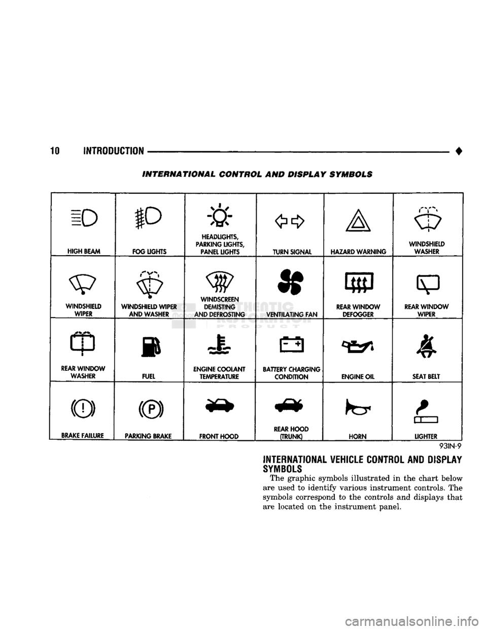
INTERNATIONAL VEHICLE CONTROL AND DISPLAY
SYMBOLS
The graphic symbols illustrated in the chart below
are used to identify various instrument controls. The
symbols correspond to the controls and displays that are located on the instrument panel.
Page 322 of 1502
•
ELECTRICAL
ELECTRICAL
8A - 1
Group
AUDIO
SYSTEMS
8F
BATTERY/STARTER/GENERATOR
SERVICE
.. 8B
BATTERY/STARTING/CHARGING
SYSTEMS
DIAGNOSTICS
8A
HORNS
8G
IGNITION
SYSTEMS
8D
INSTRUMENT PANEL AND
GAUGES
8E
LAMPS
8L
POWER
LOCKS
8P
INDEX
Group
POWER
MIRRORS
8T
POWER
WINDOWS 8S
REAR
WINDOW DEFOGGER 8N
TURN
SIGNALS
AND HAZARD WARNING
FLASHERS
8J
VEHICLE
SPEED
CONTROL SYSTEM 8H WARNING BUZZER SYSTEM 8U
WINDSHIELD WIPERS AND
WASHERS
8K
WIRING DIAGRAMS 8W
BATTERY/STARTING/CHARGING SYSTEMS DIAGNOSTICS
CONTENTS
page
page
BATTERY TEST
PROCEDURES
2 GENERATOR TEST
PROCEDURES
ON VEHICLE . 13
ENGINE
STARTER MOTOR TEST
PROCEDURES
..9 SPECIFICATIONS 18
GENERAL
INFORMATION 1
GENERAL INFORMATION
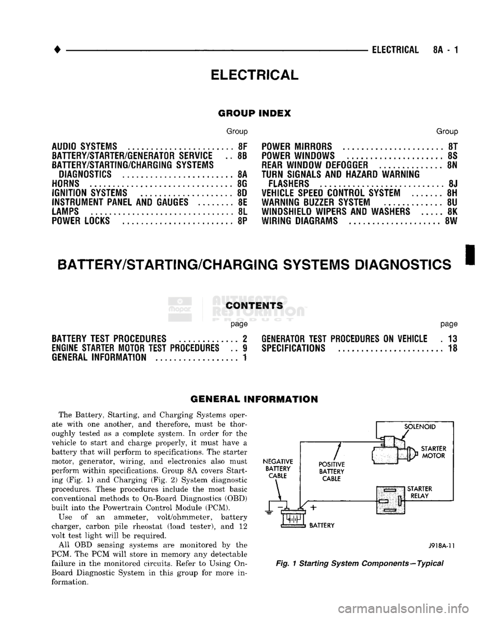
The Battery, Starting, and Charging Systems oper
ate with one another, and therefore, must be thor
oughly tested as a complete system. In order for the
vehicle to start and charge properly, it must have a
battery that will perform to specifications. The starter
motor, generator, wiring, and electronics also must
perform within specifications. Group 8A covers Start ing (Fig. 1) and Charging (Fig. 2) System diagnostic
procedures. These procedures include the most basic
conventional methods to On-Board Diagnostics (OBD)
built into the Powertrain Control Module (PCM).
Use of an ammeter, volt/ohmmeter, battery
charger, carbon pile rheostat (load tester), and 12
volt test light will be required.
All OBD sensing systems are monitored by the
PCM. The PCM will store in memory any detectable
failure in the monitored circuits. Refer to Using On-
Board Diagnostic System in this group for more in formation.
NEGATIVE
BATTERY
CABLE
A
7
POSITIVE
BATTERY
CABLE
BATTERY
J918A-11
Fig.
1 Starting
System
Components—Typical
Page 400 of 1502
•
INSTRUMENT PANEL
AND
GAUGES
8E - 19
MESSAGE
CENTER
PRINTED CIRCUIT BOARD
J918E-33
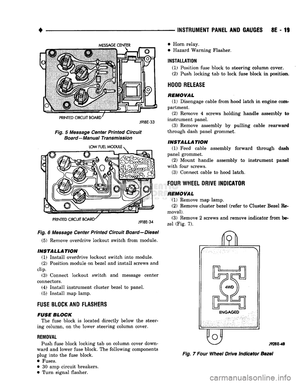
Fig.
5
Message
Center Printed Circuit
Board—Manual
Transmission
LOW FUEL MODULE
>
PRINTED CIRCUIT BOARD
J918E-34
Fig.
6
Message
Center Printed Circuit
Board—Diesel
(5) Remove overdrive lockout switch from module.
INSTALLATION
(1) Install overdrive lockout switch into module.
(2) Position module on bezel and install screws and
clip.
(3) Connect lockout switch and message center
connectors.
(4) Install instrument cluster bezel to panel.
(5) Install map lamp.
FUSE
BLOCK AND
FLASHERS
FUSE
BLOCK
The fuse block is located directly below the steer
ing column, on the lower steering column cover.
REMOVAL
Push fuse block locking tab on column cover down
ward and lower fuse block. The following components
plug into the fuse block.
• Fuses. • 30 amp circuit breakers.
• Turn signal flasher. • Horn relay.
• Hazard Warning Flasher.
INSTALLATION
(1) Position fuse block to steering column cover. (2) Push locking tab to lock fuse block in position.
HOOD
RELEASE
REMOVAL
(1) Disengage cable from hood latch in engine com
partment. (2) Remove 4 screws holding handle assembly to
instrument panel.
(3) Remove assembly by pulling cable rearward
through dash panel grommet.
INSTALLATION
(1) Feed cable assembly forward through dash
panel grommet.
(2) Mount handle assembly to instrument panel
with four screws.
(3) Connect cable to hood latch.
FOUR
WHEEL
DRIVE
INDICATOR
REMOVAL
(1) Remove map lamp.
(2) Remove cluster bezel (refer to Cluster Bezel Re
moval).
(3) Remove 2 screws and remove indicator from be
zel (Fig. 7).
o
J928E-48
Fig.
7
Four
Wheel
Drive Indicator
Bezel
Page 412 of 1502
•
HORNS
8G - 1
HORNS
CONTENTS
SERVICE
PROCEDURES
page
.. 3
TEST PROCEDURES
page
.. 1
GENERAL
INFORMATION plied from the fuse block and grounded in the horn The horn system consists of a horn switch, horn re- switch. When the horn switch on the steering column
lay (located on the fuse block), horns, and all their is pressed, the ground circuit is completed, energiz-
wiring and connections. The circuit voltage is sup- ing the relay, and supplying power to the horns.
TEST PROCEDURES
HORNS
WILL
NOT
SOUND
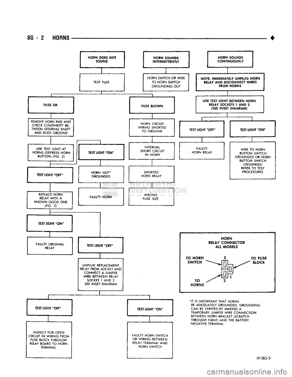
If the horns do not sound, check for a blown horn
fuse in cavity number 4 of the fuse block. If the fuse is blown, replace it with the same type fuse. If the
horns fail to sound and the newly replaced fuse blows
the horn switch is depressed, check for one of the fol lowing:
• a short circuit in the horn
• the horn wiring between the fuse terminal and the
horn is faulty. If the fuse is intact, unplug wire connector at horn.
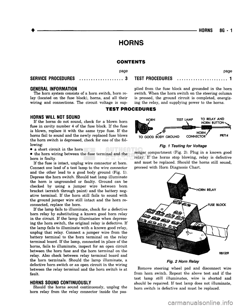
Connect one lead of a test lamp to the wire connector and the other lead to a good body ground (Fig. 1).
Depress the horn switch. Should test lamp illuminate
the horn is ungrounded or faulty. Ground can be checked by using a jumper wire between horn
bracket (scratch through paint) and the battery neg ative terminal. If the horn still fails to sound with
the ground jumper wire still intact and the horn re connected, replace the horn. If the lamp fails to illuminate, check for a defective
horn relay by substituting a known good horn relay in the circuit. If the lamp illuminates when depress
ing the horn switch, the original relay is defective. If
the lamp fails to illuminate with a known good relay, unplug that relay. Connect a jumper wire from the
battery terminal to the horn terminal on the relay
terminal board. If the lamp, connected in place of the
horns, fails to illuminate, inspect for an open circuit
between the horn fuse and the horn terminal on the relay. Also check between relay terminal board and
the horn terminals. Should the lamp illuminate, a defective horn switch or an open circuit in the wiring
between the relay terminal and the horn switch is at fault.
HORNS SOUND CONTINUOUSLY
Should the horns sound continuously, unplug the
horn relay from the relay connector inside the pas-
HORN
TEST LAMP TO RELAY
AND
HORN
BUTTON
-
TO GOOD BODY GROUND HORN,
CONNECTOR
PR714
Fig.
1 Testing for Voltage
senger compartment (Fig. 2). Plug in a known good
relay. If the horns stop blowing, relay is defective and must be replaced. Should the horns still sound,
proceed with Horn Diagnosis Chart.
HORN RELAY
FUSE BLOCK
RB1359
Fig.
2
Horn
Relay
Remove steering wheel pad and disconnect wire
from horn switch. Repeat the above test and if the
test lamp still illuminates, wire is shorted and should be repaired. If test lamp does not illuminate,
horn switch is defective and must be replaced.
Page 413 of 1502
8G
- 2
HORNS
•
HORN
DOES NOT
SOUND HORN SOUNDS
INTERMITTENTLY
TEST FUSE
HORN SOUNDS
CONTINUOUSLY
HORN SWITCH
OR
WIRE TO HORN SWITCH GROUNDING
OUT
FUSE BLOWN
REMOVE
HORN
PAD AND
CHECK
CONTINUITY
BE
TWEEN STEERING SHAFT AND BODY GROUND
NOTE:
IMMEDIA1
RELAY
AND
Dl
FRO/V
rELY UNPLUG HORN
SCONNECT
WIRES
\HORNS
USE
TEST LIGHT BETWEEN HORN
RELAY
SOCKETS
t AND 3
(SEE
INSET DIAGRAM)
HORN CIRCUIT
WIRING SHORTED TO GROUND
USE
TEST
LIGHT
AT
HORNS
(DEPRESS
HORN
BUTTON)
(FIG.
2)
TEST LIGHT' ON
TEST
UGHT
"OFF" TEST LIGHT "OFF"
INTERNAL
SHORT CIRCUIT IN HORN
HORN
NOT*
GROUNDED
REPLACE
HORN
RELAY
WITH
A
KNOWN GOOD
ONE
(FIG.
3)
TEST LIGHT "ON"
FAULTY
HORN RELAY
SHORTED
HORN RELAY WIRE
TO
HORN
BUTTON SWITCH
GROUNDED
OR
HORN BUTTON SWITCH
GROUNDED
REFER
TO
TEST
PROCEDURES
FAULTY HORN WRONG
FUSE
SIZE
TEST LIGHT "ON"
FAULTY ORIGINAL
RELAY
TEST LIGI
HT
"OFF"
UNPLUG REPLACEMENT
RELAY
FROM SOCKET
AND
CONNECT
A
JUMPER
WIRE BETWEEN RELAY
SOCKET
1
AND
2
SEE
INSET DIAGRAM
INSPECT
FOR
OPEN
CIRCUIT
IN
WIRING FROM
FUSE
BLOCK THROUGH
RELAY
BOARD
TO
HORN TERMINAL FAULTY HORN SWITCH
OR
WIRING BETWEEN
RELAY
TERMINAL
AND
HORN SWITCH
HORN
RELAY CONNECTOR ALL MODELS
TO HORN SWITCH
TO
HORNS
TO
FUSE
BLOCK
*IT
IS
IMPORTANT
THAT
HORNS
BE
ADEQUATELY GROUNDED. GROUNDING
CAN
BE
VERIFIED
BY
MAKING
A
TEMPORARY
JUMPER WIRE CONNECTION BETWEEN HORN BRACKET (SCRATCH
THROUGH
PAINT)
AND THE
BATTERY
NEGATIVE TERMINAL.
J918G-5
Page 414 of 1502
•
HORNS
8G - 3
SERVICE
PROCEDURES
HORN
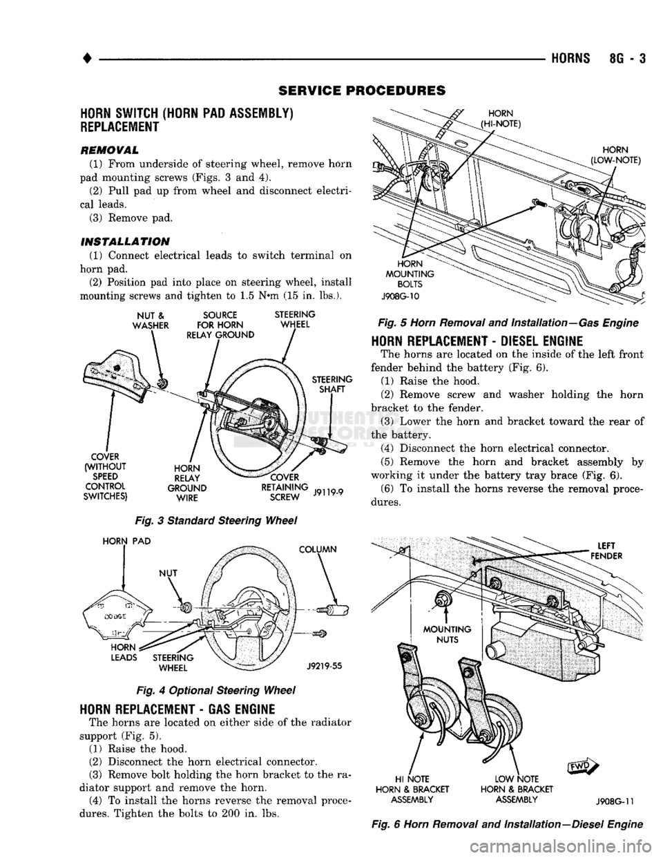
SWITCH (HORN PAD ASSEMBLY)
REPLACEMENT
REMOVAL (1) From underside of steering wheel, remove horn
pad mounting screws (Figs. 3 and 4). (2) Pull pad up from wheel and disconnect electri
cal leads. (3) Remove pad.
INSTALLATION
(1) Connect electrical leads to switch terminal on
horn pad. (2) Position pad into place on steering wheel, install
mounting screws and tighten to 1.5 N*m (15 in. lbs.).
NUT
&
WASHER
SOURCE
FOR HORN
RELAY GROUND STEERING
WHEEL
STEERING SHAFT
COVER
(WITHOUT
SPEED
CONTROL
SWITCHES) HORN
RELAY
GROUND WIRE COVER
RETAINING
SCREW
J9119-9
Fig.
3 Standard Steering
Wheel
HORN
PAD
COLUMN
HORN
LEADS
STEERING WHEEL
J9219-55
Fig.
4 Optional Steering
Wheel
HORN
REPLACEMENT
-
GAS ENGINE
The horns are located on either side of the radiator
support (Fig. 5). (1) Raise the hood.
(2) Disconnect the horn electrical connector.
(3) Remove bolt holding the horn bracket to the ra
diator support and remove the horn. (4) To install the horns reverse the removal proce
dures.
Tighten the bolts to 200 in. lbs.
HORN
(HI-NOTE)
HORN
(LOW-NOTE)
HORN
MOUNTING
BOLTS
J908G-10
Fig.
5
Horn
Removal
and Installation—Gas
Engine
HORN
REPLACEMENT
-
DIESEL ENGINE
The horns are located on the inside of the left front
fender behind the battery (Fig. 6). (1) Raise the hood.
(2) Remove screw and washer holding the horn
bracket to the fender. (3) Lower the horn and bracket toward the rear of
the battery. (4) Disconnect the horn electrical connector.
(5) Remove the horn and bracket assembly by
working it under the battery tray brace (Fig. 6). (6) To install the horns reverse the removal proce
dures.
LEFT
FENDER
HI NOTE
HORN
&
BRACKET
ASSEMBLY
LOW NOTE
HORN
&
BRACKET
ASSEMBLY
J908G-11
Fig.
6
Horn
Removal
and Installation—Diesel
Engine
Page 427 of 1502
8H
- 12
VEHICLE SPEED CONTROL SYSTEM
•
SERVO
THROTTLE CABLE ASSEMBLY—DIESEL
ENGINE
REMOVAL (1) Remove hairpin clip and washer retaining ca
bles on bellcrank. Remove servo throttle cable from bellcrank.
(2) Remove servo throttle cable from cable support
bracket.
(3) Remove 2 nuts from servo mounting bracket.
(4) Pull servo away from mounting bracket.
(5) Remove and discard push nuts on servo studs. (6) Pull speed control cable away from servo to ex
pose cable retaining clip. (7) Remove clip attaching cable to servo.
(8) Disconnect cable at servo and remove cable as
sembly.
INSTALLATION (1) Locate cable through servo mounting bracket.
(2) Connect cable sleeve to servo stud, align holes,
and install hairpin clip.
(3) Insert servo studs through holes in cable.
(4) Install new push nuts on servo studs.
(5) Insert servo studs through holes in bracket. In
stall nut washers and torque to 6 N*m (50 in. lbs.).
(6) Route cable from servo, to cable support
bracket, (7) Install cable end on bellcrank rod.
(8) Adjust cable as described under speed control
cable adjustment. (9) Install washer and hairpin clip on end of bell
crank rod.
SPEED
CONTROL
SWITCH
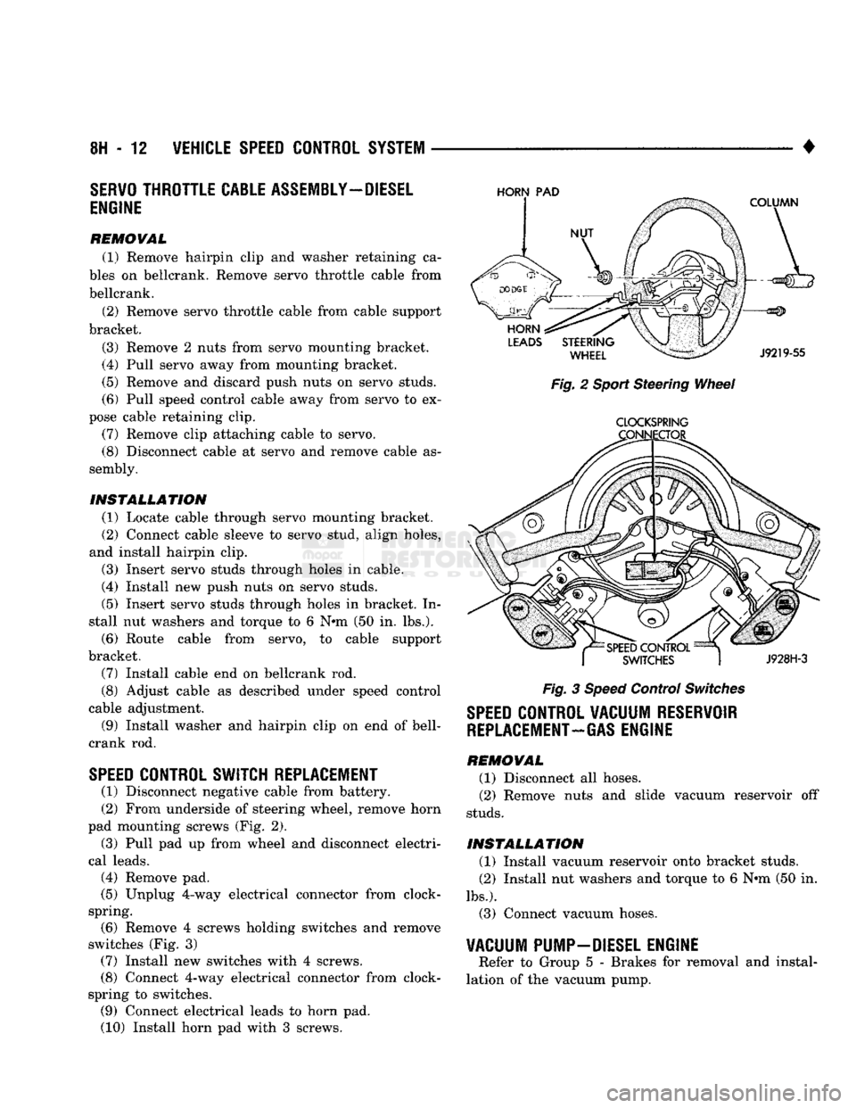
REPLACEMENT
(1) Disconnect negative cable from battery.
(2) From underside of steering wheel, remove horn
pad mounting screws (Fig. 2).
(3) Pull pad up from wheel and disconnect electri
cal leads.
(4) Remove pad.
(5) Unplug 4-way electrical connector from clock-
spring. (6) Remove 4 screws holding switches and remove
switches (Fig. 3) (7) Install new switches with 4 screws.
(8) Connect 4-way electrical connector from clock-
spring to switches. (9) Connect electrical leads to horn pad.
(10) Install horn pad with 3 screws.
HORN
PAD
Fig. 2 Sport Steering Wheel
CLOCKSPRING
Fig. 3 Speed Control Switches
SPEED
CONTROL VACUUM RESERVOIR
REPLACEMENT-GAS
ENGINE
REMOVAL (1) Disconnect all hoses.
(2) Remove nuts and slide vacuum reservoir off
studs.
INSTALLATION (1) Install vacuum reservoir onto bracket studs.
(2) Install nut washers and torque to 6 Nrn (50 in.
lbs.).
(3) Connect vacuum hoses.
VACUUM PUMP-DIESEL ENGINE
Refer to Group 5 - Brakes for removal and instal
lation of the vacuum pump.
Page 429 of 1502
8J
- 2
TURN SIGNALS AND HAZARD WARNING FLASHER
•
FUSE
BLOCK
INSTRUMENT
PANEL
REAR
VIEW
HAZARD
WARNING
FLASHER
VIEW
IN DIRECTION OF
ARROW
RR8JC10
Fig.
1 Turn
Signal
and Hazard Warning
Flashers
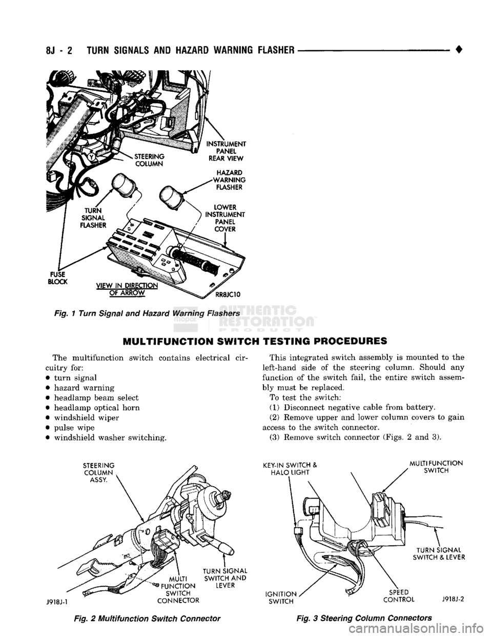
MULTIFUNCTION
SWITCH TESTING PROCEDURES
The multifunction switch contains electrical cir
cuitry for:
• turn signal
• hazard warning
• headlamp beam select
• headlamp optical horn
• windshield wiper
• pulse wipe • windshield washer switching. This integrated switch assembly is mounted to the
left-hand side of the steering column. Should any
function of the switch fail, the entire switch assem
bly must be replaced.
To test the switch: (1) Disconnect negative cable from battery.
(2) Remove upper and lower column covers to gain
access to the switch connector. (3) Remove switch connector (Figs. 2 and 3).
Fig.
2 Multifunction
Switch
Connector
Fig.
3 Steering
Column
Connectors