1993 DODGE TRUCK change time
[x] Cancel search: change timePage 3 of 1502

FOREWORD
The information contained in this service manual has been prepared for the professional automotive tech
nician involved in daily repair operations. This manual does not cover theory of operation, which is addressed in service training material. Information describing the operation and use of standard and optional equipment
is included in the Owner's Manual provided with the vehicle.
Information in this manual is divided into groups. These groups contain general information, diagnosis,
testing, adjustments, removal, installation, disassembly, and assembly procedures for the components.
The Component and System Index of this manual identifies the correct group for the component or system
to be serviced. In addition, a Service Manual Comment form is included at the rear of this manual. Use the form to provide Chrysler Corporation with your comments and suggestions.
To assist in locating a group title page, use the Group Tab Locator on the following page. The solid bar
after the group title is aligned to a solid tab on the first page of each group. The first page of the group has
a contents section that lists major topics within the group.
Tightening torques are provided as a specific value throughout this manual. This value represents the
midpoint of the acceptable engineering torque range for a given fastener application. These torque values are
intended for use in service assembly and installation procedures using the correct OEM fasteners. When re
placing fasteners, always use the same type (part number) fastener as removed.
Chrysler Corporation reserves the right to change testing procedures, specifications, diagnosis, repair
methods, or vehicle wiring at any time without prior notice or incurring obligation.
NOTE: The acronyms, terminology and nomenclature used to identify emissions related components in
this manual may have changed from prior publications. These new terms are in compliance with S.A.E.
recommended practice J1930. This terminology standard (J1930) is required to comply with the 1993 California Air Research Board (CARB) requirements.
Page 24 of 1502
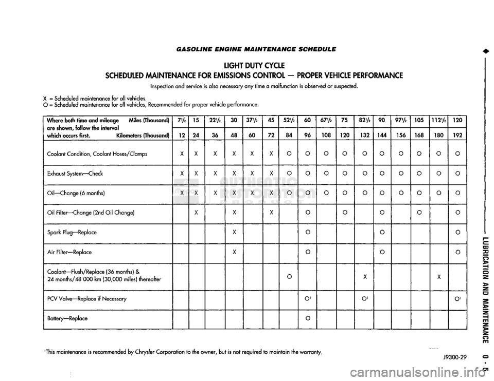
GASOLINE ENGINE MAINTENANCE SCHEDULE
LIGHT
DUTY
CYCLE
SCHEDULED
MAINTENANCE
FOR
EMISSIONS
CONTROL
-
PROPER
VEHICLE
PERFORMANCE
Inspection and service is also necessary any
rime
a
malfunction
is observed or suspected.
X
= Scheduled maintenance for all vehicles.
O
= Scheduled maintenance for all vehicles, Recommended for proper
vehicle
performance.
Where both
time
and mileage Miles (Thousand) are
shown,
follow the
interval
which
occurs
first. Kilometers (Thousand) 7'A
15
22'A
30
37'A
45
52'A
60
67'A
75
82'A
90 97'/2 105 112'A
120
Where both
time
and mileage Miles (Thousand)
are
shown,
follow the
interval
which
occurs
first. Kilometers (Thousand) 12 24
36 48
60 72 84 96 108 120
132 144 156 168 180 192
Coolant
Condition,
Coolant
Hoses/Clomps
X X X X X X
O O O O O
O O O
o
O
Exhaust
System—Check
X
X X X X
X
O O O
o
O
O O
o o o
Oil—Change
(6 months)
X X X X X X
O O O
o o
O O
o o
o
Oil Filter—Change (2nd Oil Change)
X
X X
o o
O
o
o
Spark
Plug—Replace
X
0
o o
Air
Filter—Replace
X
o
O
o
Coolant—Flush/Replace
(36 months) &
24
months/48 000 km
(30,000
miles)
thereafter
O
X
X
PCV
Valve—Replace if
Necessary
O'
O' O'
Battery—Replace
O
This maintenance is recommended by Chrysler Corporation to the owner, but is not
required
to
maintain
the
warranty.
Page 25 of 1502

0 - 6
LUBRICATION
AND
MAINTENANCE
GASOLINE ENGINE MAINTENANCE SCHEDULE
HEAVY
DUTY
CYCLE
Inspection and service is also necessary anytime
a
malfunction is observed or suspected.
When both
time
and mileage
are
Miles (Thousand)
shewn,
follow
the
interval
which occurs first. Kilometers (Thousand) 6
12 18 24
30 36 42 48 54
60 66 72
78
82V2
84 90
96
102 108
When both
time
and mileage
are
Miles (Thousand)
shewn,
follow
the
interval
which occurs first. Kilometers (Thousand) 9.6 19 29
38 48 58 67 77
85 96 106 116
125 132
135
145
154 164
174
Coolant
Condition, Coolant
Hoses/Clamps
X
X X X
X X X X
X X X X
X X X
X X X
Exhaust
System
—
Check
X X X X X X X X X X X
X X X X X
X X
Oil
—
Change
(6
Months)
X X X X X X X
X X
X
X
X
X X X
X X
X
Oil
Filter
—
Change (2nd
Oil
Change)
X X X X
X X
X X
X
Drive Belt Tension
—
Inspect
&
Adjust
X' X
X1
X X' X
Drive Belts (V-Type)
—
Replace
X
Air
Filter/Air
Pump
Air
Filter
—
Replace
X X X
X
Crankcase
Inlet
Air
Filter
(6 &
8
Cyl.
Eng.
Only)
—
Clean
X X
X X
Spark
Plug
—
Replace
X X X
Fuel
Filter
—
Replace as necessary
Coolant
—
Flush/Replace
(36
months)
& 24
months/48
000 km
(30,000
miles)
thereafter
X
EGR
Valve
&
Tube
—
Replace X2
EGR
Tube
—
Clean Passengers
X2
PCV
Valve
—
Replace X2
Vacuum
Emission
Components
—
Replace
X
Ignition Timing
—
Adjust
to
Specs,
as necessary X
Ignition Cables, Distributor Cap
&
Rotor
—
Replace
X
Manifold Heat Control Valve
—
Lubricate
X
Battery
—
Replace X
Oxygen
Sensor
—
Replace
X2
1 For California vehicles, this maintenance is recommended
by
Chrysler Motors
to the
owner but, is not
required
to
maintain the
warranty
on the
air
pump drive
belt.
2 Requires
Emission
Maintenance Reminder Light.
If
so equipped, these parts
are to be
replaced
at the
indicated mileage,
or
when the
emissions
maintenance reminded light remains on continuously
with
the key in the
"on" position, whichever occurs first.
J9100-20
DIESEL
ENGINE
MAINTENANCE
SCHEDULE
HEAVY
DUTY
CYCLE
Inspection
and
service
is
also
necessary
any
time
a
malfunction
is
observed
or
suspected.
Iff both
time
and distance Miles (Thousand)
are listed, use the
interval
that
ends
first. Kilometers (Thousand) 6
12
18 24
30 36 42
4S
54
60 66
72 78
84 90 96
102 108
Iff both
time
and distance Miles (Thousand)
are listed, use the
interval
that
ends
first. Kilometers (Thousand) 9,6 19
29
38 48 58 67
77
85 96 106
116 125 135 145 154
164 174
Coolant
Condition, Coolant
Hoses/Clamps
(12 months)
Coolant
Flush/Replace (36 months) & 24 months/
48 000 km
(30,000
miles)
thereafter
O
Oil—Change
(6 months)
X X X
X X X
X X X X X
X X X X X X
X
Oil Filter—Replace (Every Oil Change)
X X X
X X X
X X
X X X
X
X X X X
X X
Drive Belts—Replace
As
Necessary
X X
X X X X
Air Filter—Replace
X X
X X
Air Filter—Clean (California Only) e
®
• •
Air
Filter
Canister—Clean
o o o
o
Fuel Filter—Service When Necessary
Injection
Pump
Timing & Engine Idle Speed—
Check
& Adjust
©
• 9 • • •
Underhood Rubber/Plastic Components—Inspect/Replace • • • • •
X
— All vehicles
O
— All
vehicles
except
California.
Recommended
for
California.
•
— California only.
Recommended
for all vehicles.
Page 33 of 1502

0 - 14
LUBRICATION
AND
MAINTENANCE
•
ENGINE
MAINTENANCE
INDEX
page
Air
Injection
Systems/Air Pump
. 17
Air-Conditioner
Compressor
21
Battery
19
Cooling System
15
Crankcase
Ventilation
System
17
Diesel Engine
Air Filter
Canister
17
Drive Belts
20
Engine
Air
Cleaner
Filter
Element
16
Engine Break-In
14
Engine
Oil 14
Engine
Oil
Change
and Filter
Replacement
15
Exhaust Gas
Recirculation
(EGR) System
...... 19
page
Exhaust
Manifold
Heat
Control
Valve
. 17
Exhaust System
, 21
Fuel System
18
Hoses
and
Fittings
16
Ignition
Cables,
Distributor
Cap and
Rotor
...... 19
Ignition
Timing
. 19
Oxygen
(02)
Sensor
19
Rubber/Plastic Components
20
Spark Plugs
. 19
Throttle
Control
Linkage
18
Vacuum Operated, Emission
Control
Components
19
ENGINE BREAK-IN
After first starting a new engine, allow it to idle
for 15 seconds before shifting into a drive gear. Also:
• Drive the vehicle at varying speeds less than 88
km/h (55 mph) for the first 480 km (300 miles).
• Avoid fast acceleration and sudden stops.
• Do not drive at full-throttle for extended periods of
time
• Do not drive at constant speeds
• Do not idle the engine excessively A special break-in engine oil is not required. The
original engine oil installed is a high quality lubri
cant. New engines tend to consume more fuel and oil un
til after the break-in period has ended.
ENGINE
OIL SPECIFICATIONS
API SERWICE
GRADE
Use an engine oil that conforms to API Service
Grade S5 SG/CD or SG/CE. MOPAR®provides engine
oils that conform to all of these service grades.
SULFATED ASH—DIESEL ENGINES
Oils that contain an excessive amount of sulfated
ash can cause deposits to develop on Diesel engine
valves. These deposits can result in valve wear.
SAE
WISC0SITY
An SAE viscosity grade is used to specify the vis
cosity of engine oil. SAE 30 specifies a single viscos
ity engine oil.
Engine oils also have multiple viscosities. 10W-30
<
5W-30
1
1 1
F
-20 0 10 20 32 60 80 100
C
-29 -18 -12 -7 0 16 27 38
ANTICIPATED
TEMPERATURE RANGE BEFORE
NEXT
OIL
CHANGE
J9000-39
Fig.
1 Temperature/Engine Oil Viscosity—Gasoline
Engines
-12°C
-18°C 10°F
0°F- 15W-40
-23°c(^-10eF
I
10W-30
WITH
WITHOUT
BLOCK HEATER
BLOCK
SYNTHETIC
OIL
HEATER
10W-30 5W-30
J9100-29
Fig.
2 Temperature/Engine Oil Viscosity—Diesel
Engines
ENERGY
G0NSERWING
OIL
An Energy Conserving type oil is recommended for
gasoline engines. They are designated as either EN
ERGY CONSERVING or ENERGY CONSERVING
II.
OIL
LEVEL
INDICATOR (DIPSTICK)
GASOLINE ENGINES
The engine oil indicator is located at the right
front of the engine.
Page 51 of 1502
0
- 32
LUBRICATION
AND
MAINTENANCE
•
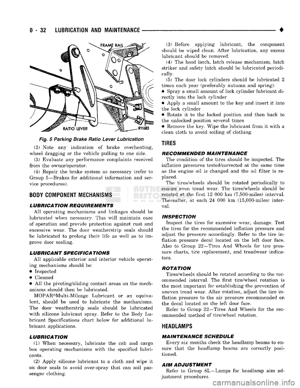
Fig.
5 Parking Brake Ratio Lever Lubrication (2) Note any indication of brake overheating,
wheel dragging or the vehicle pulling to one side.
(3) Evaluate any performance complaints received
from the owner/operator. (4) Repair the brake system as necessary (refer to
Group 5—Brakes for additional information and ser
vice procedures).
BODY
COMPONENT
MECHANISMS
LUBRICATION REQUIREMENTS
All operating mechanisms and linkages should be
lubricated when necessary. This will maintain ease of operation and provide protection against rust and
excessive wear. The door weatherstrip seals should
be lubricated to prolong their life as well as to im prove door sealing.
LUBRICANT SPECIFICATIONS
All applicable exterior and interior vehicle operat
ing mechanisms should be:
• Inspected • Cleaned
• All the pivoting/sliding contact areas on the mech anisms should then be lubricated.
MOPAR®Multi-Mileage Lubricant or an equiva
lent, should be used to lubricate the mechanisms.
The door weatherstrip seals should be lubricated
with silicone lubricant spray. Refer to the Body Lu
bricant Specifications chart below for additional lu
bricant applications.
LUBRICATION
(1) When necessary, lubricate the cab and cargo
box operating mechanisms with the specified lubri
cants.
(2) Apply silicone lubricant to a cloth and wipe it
on door seals to avoid over-spray that can soil pas
senger clothing. (3) Before applying lubricant, the component
should be wiped clean. After lubrication, any excess
lubricant should be removed.
(4) The hood latch, latch release mechanism, latch
striker and safety latch should be lubricated periodi
cally.
(5) The door lock cylinders should be lubricated 2
times each year (preferably autumn and spring): • Spray a small amount of lock cylinder lubricant di
rectly into the lock cylinder
• Apply a small amount to the key and insert it into
the lock cylinder • Rotate it to the locked position and then back to
the unlocked position several times
• Remove the key. Wipe the lubricant from it with a
clean cloth to avoid soiling of clothing.
TIRES
RECOMMENDED MAINTENANCE
The condition of the tires should be inspected. The
inflation pressures tested/corrected at the same time as the engine oil is changed and the oil filter is re
placed.
The tires/wheels should be rotated periodically to
ensure even tread wear. The tires/wheels should be
rotated at the first 12 000 km (7,500-miles) interval.
Thereafter, at each 24 000 km (15,000-miles) inter
val.
INSPECTION
Inspect the tires for excessive wear, damage. Test
the tires for the recommended inflation pressure and adjust the pressure accordingly. Refer to the tire in
flation pressure decal located on the left door face. Also to Group 22—Tires And Wheels for tire pressure charts, tire replacement, and treadwear indica
tors.
ROTATION
Tires/wheels should be rotated according to the rec
ommended interval. The first tire/wheel rotation is
the most important for establishing the prevention of uneven tread wear. After rotation, adjust the tire in
flation pressure to the air pressure recommended on
the decal located on the left door face.
Refer to Group 22—Tires And Wheels for the rec
ommended method of tire/wheel rotation.
HEADLAMPS
MAINTENANCE SCHEDULE
Every six months check the headlamp beams to en
sure that the headlamp beams are correctly posi
tioned.
AIM
ADJUSTMENT
Refer to Group 8L—Lamps for headlamp aim ad
justment procedures.
Page 224 of 1502
•
BRAKES
5 - 37
BENDIX
DISC
BRAKE
INDEX
page
Caliper Overhaul
41
Disc
Brake Inspection
39
Disc
Brakeshoe
Installation
40
Disc
Brakeshoe Removal
. 39
GENERAL
SERVICE
INFORMATION
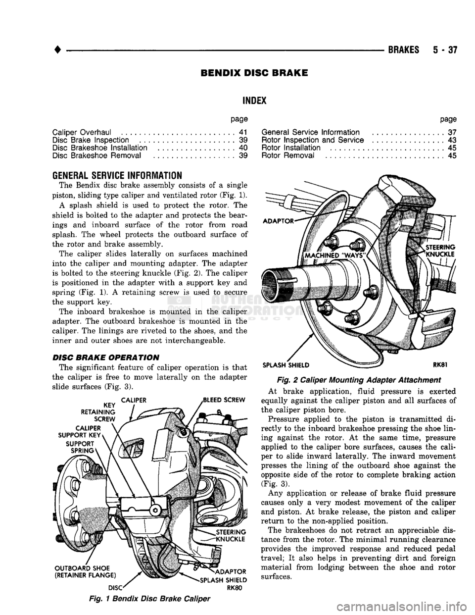
The Bendix disc brake assembly consists of a single
piston, sliding type caliper and ventilated rotor (Fig. 1). A splash shield is used to protect the rotor. The
shield is bolted to the adapter and protects the bear
ings and inboard surface of the rotor from road splash. The wheel protects the outboard surface of
the rotor and brake assembly. The caliper slides laterally on surfaces machined
into the caliper and mounting adapter. The adapter
is bolted to the steering knuckle (Fig. 2). The caliper
is positioned in the adapter with a support key and spring (Fig. 1). A retaining screw is used to secure
the support key. The inboard brakeshoe is mounted in the caliper
adapter. The outboard brakeshoe is mounted in the
caliper. The linings are riveted to the shoes, and the
inner and outer shoes are not interchangeable.
DISC
BRAKE OPERATION
The significant feature of caliper operation is that
the caliper is free to move laterally on the adapter slide surfaces (Fig. 3).
Fig.
1
Bendix
Disc
Brake Caliper
page
General Service
Information
37
Rotor Inspection
and
Service
................ 43
Rotor
Installation
45
Rotor Removal
45
Fig.
2 Caliper
Mounting
Adapter Attachment
At brake application, fluid pressure is exerted
equally against the caliper piston and all surfaces of
the caliper piston bore.
Pressure applied to the piston is transmitted di
rectly to the inboard brakeshoe pressing the shoe lin ing against the rotor. At the same time, pressure applied to the caliper bore surfaces, causes the cali
per to slide inward laterally. The inward movement
presses the lining of the outboard shoe against the
opposite side of the rotor to complete braking action (Fig. 3).
Any application or release of brake fluid pressure
causes only a very modest movement of the caliper and piston. At brake release, the piston and caliper
return to the non-applied position.
The brakeshoes do not retract an appreciable dis
tance from the rotor. The minimal running clearance
provides the improved response and reduced pedal
travel; It also helps in preventing dirt and foreign
material from lodging between the shoe and rotor surfaces.
Page 229 of 1502
5
- 42
BRAKES
•
CALIPER
DISASSEMBLY.
(1) Drain old fluid out of caliper.
(2) Pad outboard shoe side of caliper interior with
a minimum 2.54 cm (1 in.) thickness of shop towels
(Fig. 13). Towels will prevent piston damage when it
comes out of bore.
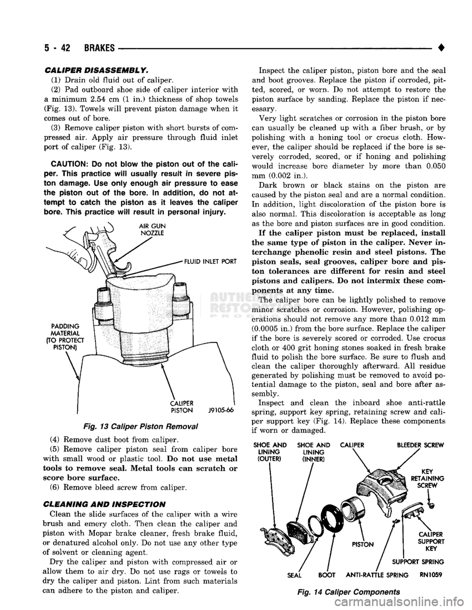
(3) Remove caliper piston with short bursts of com
pressed air. Apply air pressure through fluid inlet
port of caliper (Fig. 13).
CAUTION:
Do not
blow
the
piston
out of the
cali
per.
This
practice
will
usually
result
in
severe
pis
ton
damage.
Use only
enough
air
pressure
to
ease
the
piston
out of the
bore.
In
addition,
do not at
tempt
to catch the
piston
as it
leaves
the
caliper
bore.
This
practice
will
result
in
personal
injury.
PISTON
J9105-66
Fig.
13 Caliper
Piston
Removal (4) Remove dust boot from caliper.
(5) Remove caliper piston seal from caliper bore
with small wood or plastic tool. Do not use metal tools to remove seal. Metal tools can scratch or score bore surface. (6) Remove bleed screw from caliper.
CLEANING
AND INSPECTION Clean the slide surfaces of the caliper with a wire
brush and emery cloth. Then clean the caliper and
piston with Mopar brake cleaner, fresh brake fluid, or denatured alcohol only. Do not use any other type
of solvent or cleaning agent.
Dry the caliper and piston with compressed air or
allow them to air dry. Do not use rags or towels to
dry the caliper and piston. Lint from such materials
can adhere to the piston and caliper. Inspect the caliper piston, piston bore and the seal
and boot grooves. Replace the piston if corroded, pit
ted, scored, or worn. Do not attempt to restore the
piston surface by sanding. Replace the piston if nec essary.
Very light scratches or corrosion in the piston bore
can usually be cleaned up with a fiber brush, or by
polishing with a honing tool or crocus cloth. How ever, the caliper should be replaced if the bore is se
verely corroded, scored, or if honing and polishing
would increase bore diameter by more than 0.050
mm (0.002 in.).
Dark brown or black stains on the piston are
caused by the piston seal and are a normal condition.
In addition, light discoloration of the piston bore is also normal. This discoloration is acceptable as long as the bore and piston surfaces are in good condition.
If the caliper piston must be replaced, install
the same type of piston in the caliper. Never in
terchange phenolic resin and steel pistons. The piston seals, seal grooves, caliper bore and pis
ton tolerances are different for resin and steel
pistons and calipers. Do not intermix these com ponents at any time.
The caliper bore can be lightly polished to remove
minor scratches or corrosion. However, polishing op
erations should not remove any more than 0.012 mm (0.0005 in.) from the bore surface. Replace the caliper
if the bore is severely scored or corroded. Use crocus
cloth or 400 grit honing stones soaked in fresh brake
fluid to polish the bore surface. Be sure to flush and
clean the caliper thoroughly afterward. All residue generated by polishing must be removed to avoid po
tential damage to the piston, seal and bore after as sembly. Inspect and clean the inboard shoe anti-rattle
spring, support key spring, retaining screw and cali
per support key (Fig. 14). Replace these components if worn or damaged.
SHOE
AND
SHOE
AND
CALIPER
BLEEDER
SCREW
SEAL
BOOT
ANTI-RATTLE
SPRING
RN1059
Fig.
14 Caliper
Components
Page 294 of 1502
•
COOLING SYSTEM
7 - 23
•THERMOSTAT
MACHINED GROOVE
J9207-14
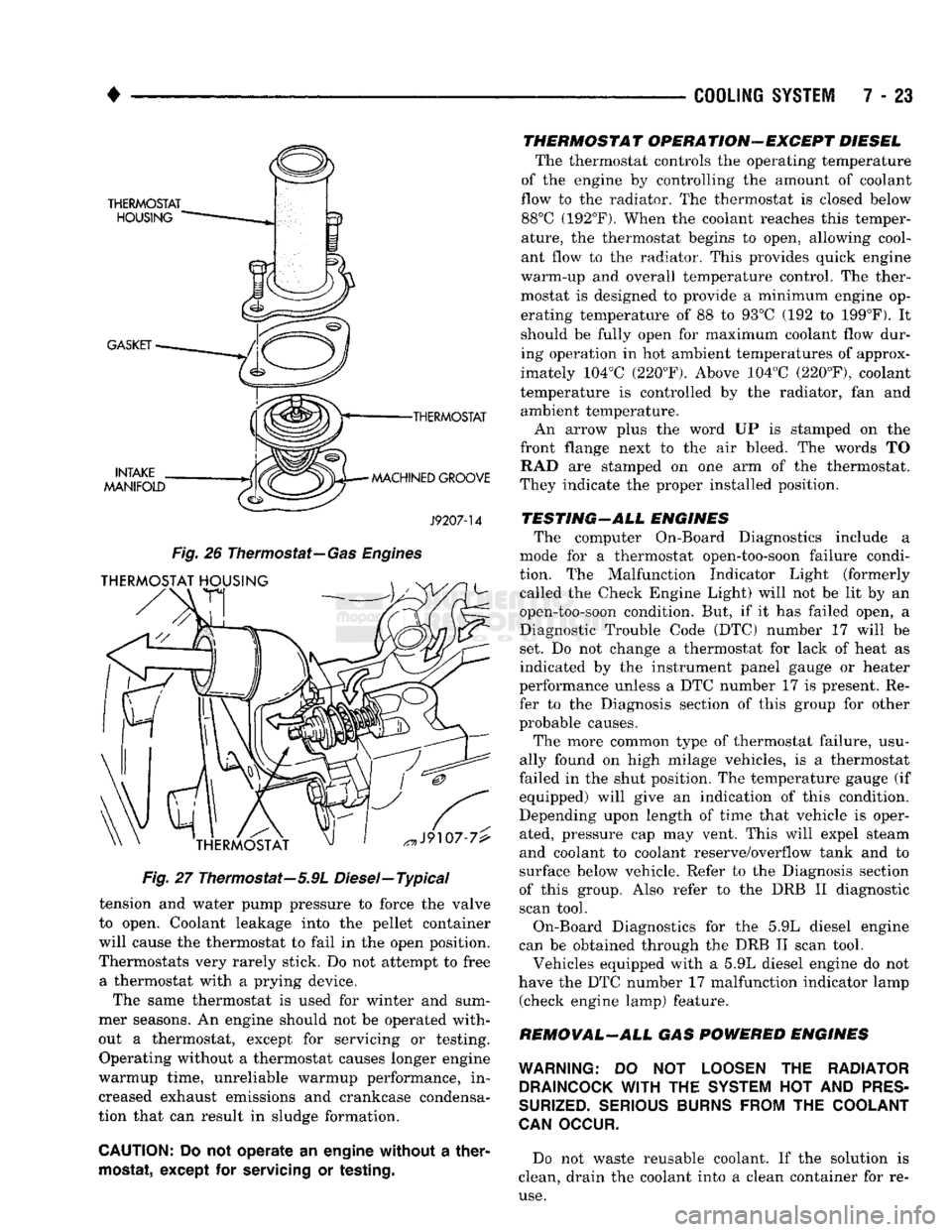
Fig.
26
Thermostat—
Gas Engines
Fig.
27 Thermostat—5.9L Diesel—Typical
tension and water pump pressure to force the valve
to open. Coolant leakage into the pellet container
will cause the thermostat to fail in the open position.
Thermostats very rarely stick. Do not attempt to free a thermostat with a prying device.
The same thermostat is used for winter and sum
mer seasons. An engine should not be operated with
out a thermostat, except for servicing or testing. Operating without a thermostat causes longer engine
warmup time, unreliable warmup performance, in
creased exhaust emissions and crankcase condensa
tion that can result in sludge formation.
CAUTION:
Do not operate an engine without a
ther
mostat,
except for
servicing
or
testing.
THERMOSTAT OPERATION-EXCEPT DIESEL
The thermostat controls the operating temperature
of the engine by controlling the amount of coolant
flow to the radiator. The thermostat is closed below 88°C (192°F). When the coolant reaches this temper
ature, the thermostat begins to open, allowing cool
ant flow to the radiator. This provides quick engine
warm-up and overall temperature control. The ther
mostat is designed to provide a minimum engine op erating temperature of 88 to 93°C (192 to 199°F). It
should be fully open for maximum coolant flow dur
ing operation in hot ambient temperatures of approx
imately 104°C (220°F). Above 104°C (220°F), coolant
temperature is controlled by the radiator, fan and ambient temperature.
An arrow plus the word UP is stamped on the
front flange next to the air bleed. The words TO RAD are stamped on one arm of the thermostat.
They indicate the proper installed position.
TESTING-ALL ENGINES The computer On-Board Diagnostics include a
mode for a thermostat open-too-soon failure condi
tion. The Malfunction Indicator Light (formerly called the Check Engine Light) will not be lit by an
open-too-soon condition. But, if it has failed open, a
Diagnostic Trouble Code (DTC) number 17 will be
set. Do not change a thermostat for lack of heat as
indicated by the instrument panel gauge or heater
performance unless a DTC number 17 is present. Re
fer to the Diagnosis section of this group for other
probable causes.
The more common type of thermostat failure, usu
ally found on high milage vehicles, is a thermostat
failed in the shut position. The temperature gauge (if equipped) will give an indication of this condition.
Depending upon length of time that vehicle is oper
ated, pressure cap may vent. This will expel steam
and coolant to coolant reserve/overflow tank and to
surface below vehicle. Refer to the Diagnosis section
of this group. Also refer to the DRB II diagnostic
scan tool.
On-Board Diagnostics for the 5.9L diesel engine
can be obtained through the DRB II scan tool.
Vehicles equipped with a 5.9L diesel engine do not
have the DTC number 17 malfunction indicator lamp (check engine lamp) feature.
REMOVAL-ALL GAS POWERED ENGINES
WARNING:
DO NOT
LOOSEN
THE
RADIATOR DRAINCOCK
WITH
THE
SYSTEM
HOT AND
PRES
SURIZED.
SERIOUS BURNS FROM
THE
COOLANT
CAN
OCCUR.
Do not waste reusable coolant. If the solution is
clean, drain the coolant into a clean container for re
use.