1993 DODGE TRUCK low beam
[x] Cancel search: low beamPage 15 of 1502
10 INTRODUCTION
•
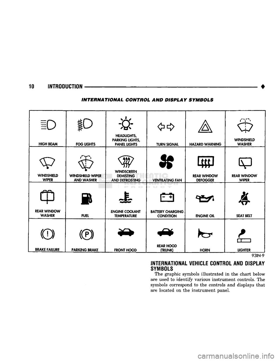
INTERNATIONAL CONTROL AND DISPLAY SYMBOLS
ID
HIGH
BEAM P
FOG UGHTS -&
HEADLIGHTS,
PARKING UGHTS, PANEL UGHTS TURN SIGNAL A
HAZARD WARNING WINDSHIELD
WASHER
WINDSHIELD WIPER WINDSHIELD WIPER
AND WASHER
AND DEFROSTING *
VENTILATING
FAN 8
M f
REAR
WINDOW DEFOGGER
sp
REARWINLX)W WIPER
CD
l
m
REAR
WINDOW WASHER FUEL ENGINE COOLANT
TEMPERATURE BATTERY CHARGING
CONDITION ENGINE OIL
SEAT
BELT
(©) (®) ky
11 J
LIGHTER
BRAKE
FAILURE
PARKING
BRAKE
FRONT HOOD
REAR
HOOD
(TRUNK)
HORN
11 J
LIGHTER
93IN-9
INTERNATIONAL VEHICLE CONTROL AND DISPLAY
SYMBOLS
The graphic symbols illustrated in the chart below
are used to identify various instrument controls. The
symbols correspond to the controls and displays that are located on the instrument panel.
Page 51 of 1502
0
- 32
LUBRICATION
AND
MAINTENANCE
•
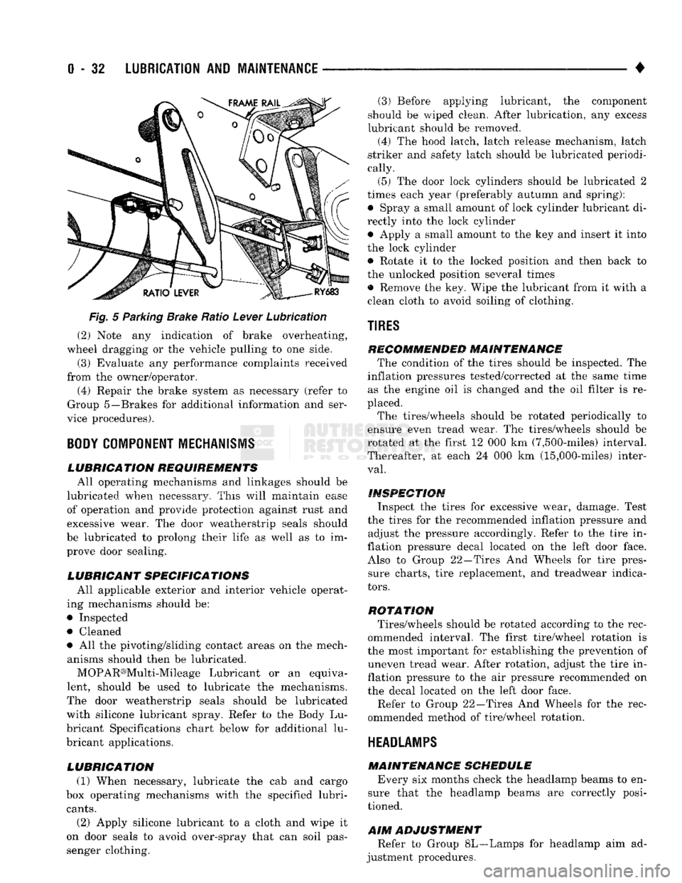
Fig.
5 Parking Brake Ratio Lever Lubrication (2) Note any indication of brake overheating,
wheel dragging or the vehicle pulling to one side.
(3) Evaluate any performance complaints received
from the owner/operator. (4) Repair the brake system as necessary (refer to
Group 5—Brakes for additional information and ser
vice procedures).
BODY
COMPONENT
MECHANISMS
LUBRICATION REQUIREMENTS
All operating mechanisms and linkages should be
lubricated when necessary. This will maintain ease of operation and provide protection against rust and
excessive wear. The door weatherstrip seals should
be lubricated to prolong their life as well as to im prove door sealing.
LUBRICANT SPECIFICATIONS
All applicable exterior and interior vehicle operat
ing mechanisms should be:
• Inspected • Cleaned
• All the pivoting/sliding contact areas on the mech anisms should then be lubricated.
MOPAR®Multi-Mileage Lubricant or an equiva
lent, should be used to lubricate the mechanisms.
The door weatherstrip seals should be lubricated
with silicone lubricant spray. Refer to the Body Lu
bricant Specifications chart below for additional lu
bricant applications.
LUBRICATION
(1) When necessary, lubricate the cab and cargo
box operating mechanisms with the specified lubri
cants.
(2) Apply silicone lubricant to a cloth and wipe it
on door seals to avoid over-spray that can soil pas
senger clothing. (3) Before applying lubricant, the component
should be wiped clean. After lubrication, any excess
lubricant should be removed.
(4) The hood latch, latch release mechanism, latch
striker and safety latch should be lubricated periodi
cally.
(5) The door lock cylinders should be lubricated 2
times each year (preferably autumn and spring): • Spray a small amount of lock cylinder lubricant di
rectly into the lock cylinder
• Apply a small amount to the key and insert it into
the lock cylinder • Rotate it to the locked position and then back to
the unlocked position several times
• Remove the key. Wipe the lubricant from it with a
clean cloth to avoid soiling of clothing.
TIRES
RECOMMENDED MAINTENANCE
The condition of the tires should be inspected. The
inflation pressures tested/corrected at the same time as the engine oil is changed and the oil filter is re
placed.
The tires/wheels should be rotated periodically to
ensure even tread wear. The tires/wheels should be
rotated at the first 12 000 km (7,500-miles) interval.
Thereafter, at each 24 000 km (15,000-miles) inter
val.
INSPECTION
Inspect the tires for excessive wear, damage. Test
the tires for the recommended inflation pressure and adjust the pressure accordingly. Refer to the tire in
flation pressure decal located on the left door face. Also to Group 22—Tires And Wheels for tire pressure charts, tire replacement, and treadwear indica
tors.
ROTATION
Tires/wheels should be rotated according to the rec
ommended interval. The first tire/wheel rotation is
the most important for establishing the prevention of uneven tread wear. After rotation, adjust the tire in
flation pressure to the air pressure recommended on
the decal located on the left door face.
Refer to Group 22—Tires And Wheels for the rec
ommended method of tire/wheel rotation.
HEADLAMPS
MAINTENANCE SCHEDULE
Every six months check the headlamp beams to en
sure that the headlamp beams are correctly posi
tioned.
AIM
ADJUSTMENT
Refer to Group 8L—Lamps for headlamp aim ad
justment procedures.
Page 382 of 1502
• • ^ ^ ^ INSTRUMENT PANEL AND GAUGES 8E - 1
CONTENTS
page
CLUSTER AND GAUGE SERVICE PROCEDURES . 12
CLUSTER AND GAUGE TEST PROCEDURES .. i
GENERAL INFORMATION . 1
page
MESSAGE CENTER-DIESEL ENGINE ........ 4
MESSAGE CENTER-GAS ENGINE .......... 3
SWITCH
AND PANEL COMPONENT SERVICE . 16
GENERAL
INFORMATION
INDEX
page
Generator
Indicating
System
2
Distance
Sensor
2
Electronic
Digital
Clock
3
Fuel
Level
Indicating
System
1
page
Malfunction
Indicator
(Check
Engine)
3
Oil
Pressure
Warning
Lamp
................. 2
Speedometer/Odometer
System
2
Temperature
and Oil
Indicating
System
......... 2
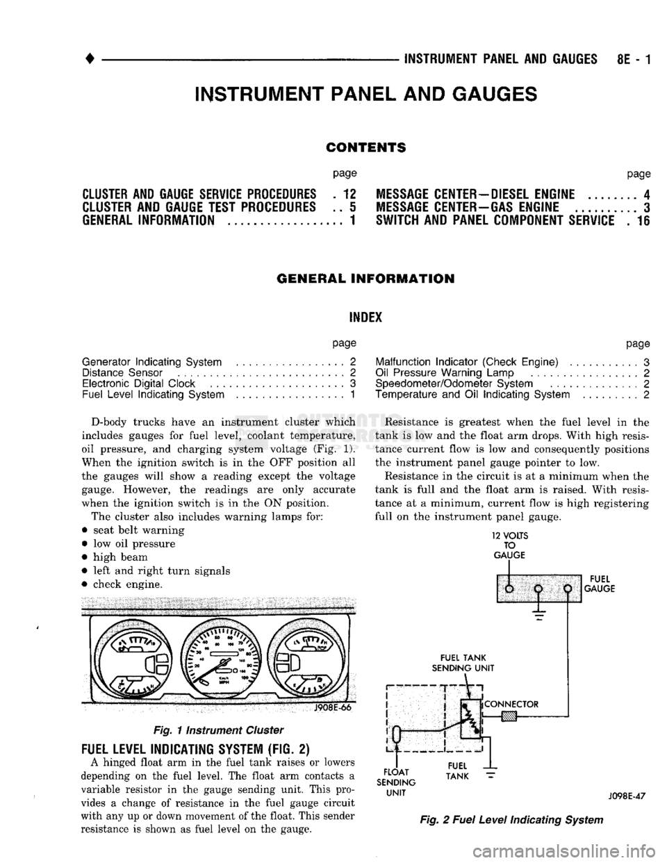
D-body trucks have an instrument cluster which
includes gauges for fuel level, coolant temperature,
oil pressure, and charging system voltage (Fig. 1).
When the ignition switch is in the OFF position all
the gauges will show a reading except the voltage gauge. However, the readings are only accurate
when the ignition switch is in the ON position.
The cluster also includes warning lamps for:
• seat belt warning
• low oil pressure
• high beam
• left and right turn signals
• check engine. J908E-66
Fig.
11nstrument
Cluster
FUEL LEVEL INDICATING SYSTEM (FIG. 2)
A hinged float arm in the fuel tank raises or lowers
depending on the fuel level. The float arm contacts a
variable resistor in the gauge sending unit. This pro
vides a change of resistance in the fuel gauge circuit
with any up or down movement of the float. This sender
resistance is shown as fuel level on the gauge. Resistance is greatest when the fuel level in the
tank is low and the float arm drops. With high resis
tance current flow is low and consequently positions
the instrument panel gauge pointer to low.
Resistance in the circuit is at a minimum when the
tank is full and the float arm is raised. With resis
tance at a minimum, current flow is high registering
full on the instrument panel gauge.
12
VOLTS
TO
GAUGE
IP
FUEL
TANK
SENDING
UNIT
FLOAT
SENDING
UNIT
1:
1
j
^
fCONNECTOR
!g|yj-»—
FUEL
GAUGE
FUEL
TANK
J098E-47
Fig.
2
Fuel
Level
Indicating
System
INSTRUMENT PANEL AND GAUGES
Page 396 of 1502
•
INSTRUMENT PANEL
AND
GAUGES
8E - 15
PRND21 INDICATOR
REMOVAL
(1) Remove bezel. Refer to Cluster Bezel Removal.
(2)
Remove cluster mask and lens. Refer to Cluster
Mask and Lens Removal. (3) Remove cluster assembly. Refer to Instrument
Cluster Removal. (4) Remove screws attaching PRND21 mechanism
to cluster housing.
(5)
Remove PRND21 mechanism.
INSTALLATION (1) Position PRND21 mechanism to cluster hous
ing. (2) Install mounting screws.
(3)
Install cluster assembly. (4) Install mask-lens.
(5)
Install bezel.
LAMP BULBS
CLUSTER ILLUMINATION LAMPS TURN SIGNAL INDICATOR LAMPS
LOW OIL PRESSURE INDICATOR LAMP
HIGH BEAM INDICATOR LAMP CHECK ENGINE LAMP
SEAT BELT WARNING LAMP
REMOVAL (1) Disconnect negative cable from battery.
(2) Remove instrument cluster. See cluster re
moval.
(3)
Twist lamp socket assembly and remove from
printed circuit board. (4) Remove bulb from socket.
INSTALLATION (1) Install bulb into socket.
(2) Install socket assembly into printed circuit
board.
(3)
Position cluster into place in panel. See cluster
installation. (4) Connect battery negative cable.
LAMP BULB REPLACEMENT—MESSAGE CENTER
REMOVAL (1) Disconnect battery negative cable.
(2) Remove instrument cluster bezel assembly. Re
fer to Instrument Cluster removal.
(3)
Twist lamp socket assembly and remove from
printed circuit board. (4) Remove bulb from socket.
INSTALLATION (1) Install bulb into socket assembly. (2) Install lamp socket assembly into printed cir
cuit board.
(3)
Install Instrument Cluster bezel assembly to
instrument panel. Refer to Instrument Cluster instal
lation.
(4) Connect negative cable from battery.
FOUR WHEEL DRIVE INDICATOR LAMP (1) Pull bulb and socket assembly from rear of
housing. (2) Remove bulb from socket.
(3)
Reverse removal procedures to install.
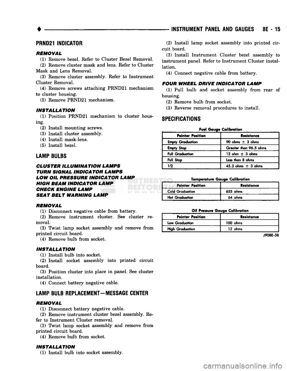
SPECIFICATIONS
Fuel
Gauge Calibration
Mntar Position Resistance
Empty Graduation 90
ohms
± 3
ohms
Empty Stop
Greater
than
96.5 ohms
Full
Graduation 12 ohm
± 3
ohms
Full
Stop
Less
than
8
ohms
1/2
45.3 ohms
± 3
ohms
Temperature
Gauge
Calibration
Pointer
Position Resistance
Cold Graduation 655 ohms
Hot Graduation 64 ohms
Oil Pressure Gauge Calibration
Pointer
Position Resistance
Low Graduation 100 ohms
High Graduation 12 ohms
J908E-58
Page 429 of 1502
8J
- 2
TURN SIGNALS AND HAZARD WARNING FLASHER
•
FUSE
BLOCK
INSTRUMENT
PANEL
REAR
VIEW
HAZARD
WARNING
FLASHER
VIEW
IN DIRECTION OF
ARROW
RR8JC10
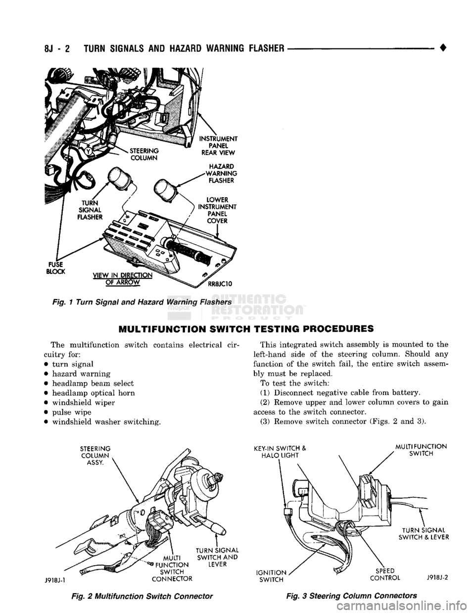
Fig.
1 Turn
Signal
and Hazard Warning
Flashers
MULTIFUNCTION
SWITCH TESTING PROCEDURES
The multifunction switch contains electrical cir
cuitry for:
• turn signal
• hazard warning
• headlamp beam select
• headlamp optical horn
• windshield wiper
• pulse wipe • windshield washer switching. This integrated switch assembly is mounted to the
left-hand side of the steering column. Should any
function of the switch fail, the entire switch assem
bly must be replaced.
To test the switch: (1) Disconnect negative cable from battery.
(2) Remove upper and lower column covers to gain
access to the switch connector. (3) Remove switch connector (Figs. 2 and 3).
Fig.
2 Multifunction
Switch
Connector
Fig.
3 Steering
Column
Connectors
Page 435 of 1502
8K - 4
WINDSHIELD WIPER
AND
WASHER
SYSTEMS
•
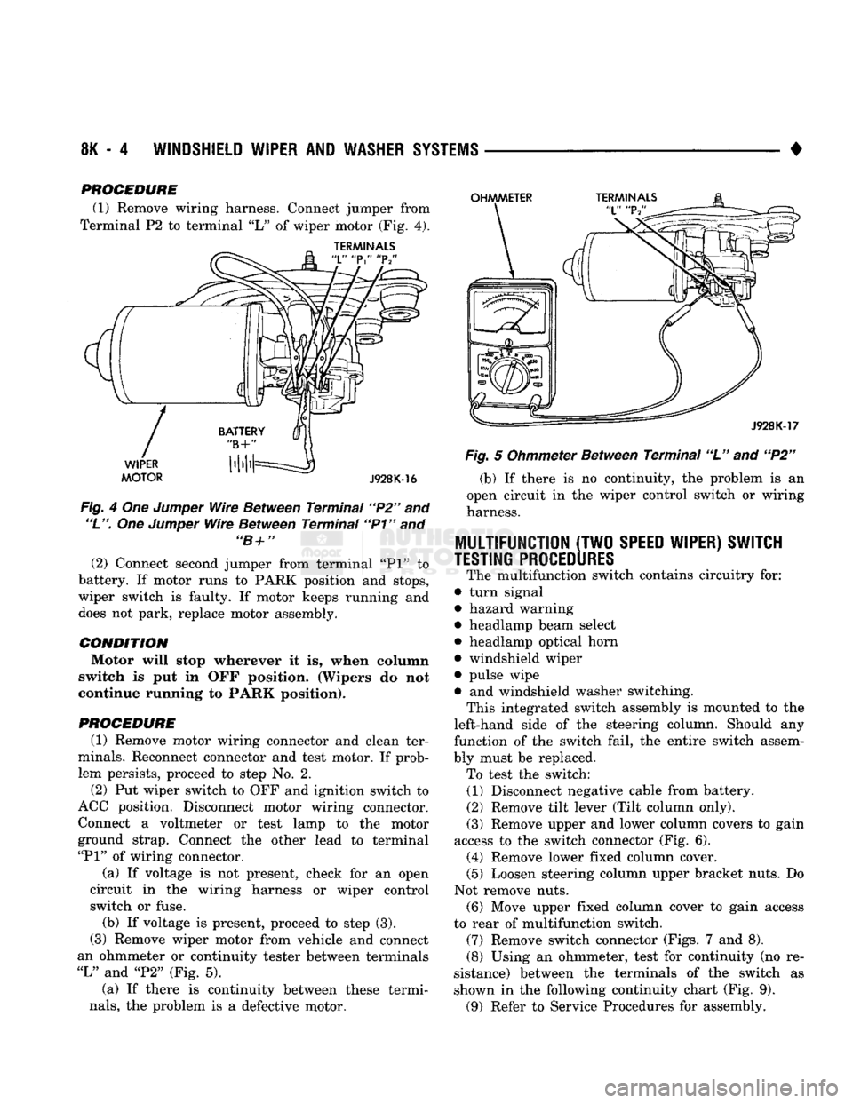
PROCEDURE (1) Remove wiring harness. Connect jumper from
Terminal P2 to terminal "L" of wiper motor (Fig, 4).
TERMINALS
Fig. 4 Om Jumper Wire Between Terminal "P2" and
"L".
One Jumper Wire Between Terminal "P1" and "B+" (2) Connect second jumper from terminal "PI" to
battery. If motor runs to PARK position and stops,
wiper switch is faulty. If motor keeps running and
does not park, replace motor assembly.
CONDITION Motor will stop wherever it is, when column
switch is put in OFF position. (Wipers do not
continue running to PARK position).
PROCEDURE
(1) Remove motor wiring connector and clean ter
minals. Reconnect connector and test motor. If prob lem persists, proceed to step No. 2.
(2) Put wiper switch to OFF and ignition switch to
ACC position. Disconnect motor wiring connector. Connect a voltmeter or test lamp to the motor
ground strap. Connect the other lead to terminal
"PI"
of wiring connector.
(a) If voltage is not present, check for an open
circuit in the wiring harness or wiper control
switch or fuse. (b) If voltage is present, proceed to step (3).
(3) Remove wiper motor from vehicle and connect
an ohmmeter or continuity tester between terminals
"L"
and "P2" (Fig. 5).
(a) If there is continuity between these termi
nals,
the problem is a defective motor. Fig. 5 Ohmmeter Between Terminal "L" and "P2"
(b) If there is no continuity, the problem is an
open circuit in the wiper control switch or wiring
harness.
MULTIFUNCTION
(TWO
SPEED WIPER) SWITCH
TESTING PROCEDURES
The multifunction switch contains circuitry for:
• turn signal
• hazard warning
• headlamp beam select
• headlamp optical horn
• windshield wiper
• pulse wipe
• and windshield washer switching. This integrated switch assembly is mounted to the
left-hand side of the steering column. Should any
function of the switch fail, the entire switch assem
bly must be replaced. To test the switch: (1) Disconnect negative cable from battery.
(2) Remove tilt lever (Tilt column only).
(3)
Remove upper and lower column covers to gain
access to the switch connector (Fig. 6). (4) Remove lower fixed column cover.
(5) Loosen steering column upper bracket nuts. Do
Not remove nuts.
(6)
Move upper fixed column cover to gain access
to rear of multifunction switch.
(7)
Remove switch connector (Figs. 7 and 8).
(8)
Using an ohmmeter, test for continuity (no re
sistance) between the terminals of the switch as
shown in the following continuity chart (Fig. 9).
(9)
Refer to Service Procedures for assembly.
Page 445 of 1502
8L
- 2
LAMPS
• This switch is mounted to the left hand side of the
steering column. Should any function of the switch
fail,
the entire switch must be replaced.
SWITCH
TEST
(1) Disconnect battery negative cable.
(2) Remove tilt lever.
(3) Remove upper and lower column covers to gain
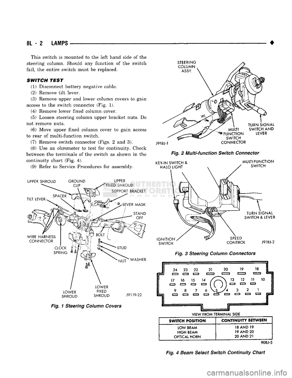
access to the switch connector (Fig. 1).
(4) Remove lower fixed column cover.
(5) Loosen steering column upper bracket nuts. Do
not remove nuts.
(6) Move upper fixed column cover to gain access
to rear of multi-function switch.
(7) Remove switch connector (Figs. 2 and 3). (8) Use an ohmmeter to test for continuity. Check
between the terminals of the switch as shown in the continuity chart (Fig. 4).
(9) Refer to Service Procedures for assembly.
UPPER SHROUD GROUND
CLIP UPPER
FIXED SHROUD
SUPPORT BRACKET
LOWER
SHROUD LOWER
FIXED
SHROUD
J9119-22
Fig.
1 Steering
Column
Covers
STEERING
COLUMN
ASSY.
J918J-1
TURN
SIGNAL
MULT
I
SWITCH
AND
*® FUNCTION
LEVER
SWITCH
CONNECTOR
Fig.
2 Multi-function
Switch
Connector
KEY-IN
SWITCH
&
HALO
LIGHT
MULTIFUNCTION
SWITCH
IGNITION
SWITCH
TURN
SIGNAL
SWITCH
&
LEVER
SPEED
CONTROL
J918J-2
Fig.
3 Steering
Column
Connectors
24 23 22 21 20 19 18
EZJ
C=3 C=3 E=3
CZZJ
E=3 E=3
17 16 15 14 13 12 11 10
a a a 8=3 ( ( ) ) 1=3 1=3 1=3 9 8 7 6 \5_y4 3 2 1
VIEW
FROM
TERMINAL
SIDE
SWITCH POSITION CONTINUITY BETWEEN
LOW
BEAM
HIGH
BEAM
OPTICAL
HORN
18 AND 19
19 AND 20
20
AND
21
908J-5
Fig.
4
Beam
Select
Switch
Continuity Chart
Page 446 of 1502

•
LAMPS
8L - 3
EXTERIOR
LAMPS
SERWICE PROCEDURES
INDEX
page
Cargo
Lamp
7
Clearance Lamps
for
Dual Wheel Model
........
5
Daytime Running
Light
Module (Canada Only)
... 8
Front
Park
and
Turn Signal Lamp Bulb
4
Headlamp
Adjustment
Using
Alignment
Screen
... 3
Headlamp
Alignment
3
Headlamp
Alignment
Preparation
3
page
Headlamp Switch
4
License
Lamp
............................
7
Sealed
Beam Replacement
4
Side
Marker Lamp
and
Bulb
. 5
Tail,
Stop, Turn Signal, Rear Side Marker
and
Back-Up
Lamps
5
Underhood Lamp
8
HEADLAMP
ALIGNMENT
Headlamps
can be
aligned using
the
screen method
provided
in
this section. Alignment Tool C4466-A
or
equivalent
can
also
be
used. Refer
to
instructions
provided with
the
tool
for
proper procedures.
The
preferred headlamp alignment setting
is 0 for
the left/right adjustment
and
1" down
for the up/
down adjustment.
HEADLAMP
ALIGNMENT PREPARATION
(1) Verify headlamp dimmer switch
and
high beam
indicator operation. (2) Correct defective components that could hinder
proper headlamp alignment. (3) Verify proper tire inflation. (4) Clean headlamp lenses.
(5) Verify that luggage area
is not
heavily loaded.
(6) Fuel tank should
be
FULL.
Add 2.94 kg (6.5
lbs.)
of
weight over
the
fuel tank
for
each estimated
gallon
of
missing fuel.
HEADLAMP
ADJUSTMENT USING ALIGNMENT
SCREEN
ALIGNMENT SCREEN PREPARATION (1) Position vehicle
on a
level surface perpendicu
lar
to a
flat wall
7.62
meters
(25 ft)
away from front
of headlamp lens.
(2)
If
necessary, tape
a
line
on the
floor
7.62
meters
(25 ft)
away from
and
parallel
to the
wall.
CENTER
OF
VEHICLE
TO
CENTER
OF
HEADLAMP
LENS
VEHICLE
CENTERLINE" LOW BEAM
HOT
SPOT AREA FLOOR
TO
CENTER
OF
HEADLAMP
LENS
PREFERRED
HOT SPOT
LOCATION
7.62
METERS
(25
FEET)
FRONT
OF
HEADLAMP
938L-25X
Fig.
1 Headlamp
Alignment
Screen
—Typical