1993 DODGE TRUCK lights
[x] Cancel search: lightsPage 15 of 1502
10 INTRODUCTION
•
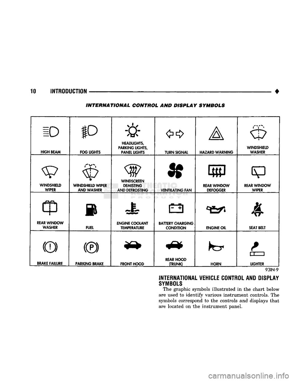
INTERNATIONAL CONTROL AND DISPLAY SYMBOLS
ID
HIGH
BEAM P
FOG UGHTS -&
HEADLIGHTS,
PARKING UGHTS, PANEL UGHTS TURN SIGNAL A
HAZARD WARNING WINDSHIELD
WASHER
WINDSHIELD WIPER WINDSHIELD WIPER
AND WASHER
AND DEFROSTING *
VENTILATING
FAN 8
M f
REAR
WINDOW DEFOGGER
sp
REARWINLX)W WIPER
CD
l
m
REAR
WINDOW WASHER FUEL ENGINE COOLANT
TEMPERATURE BATTERY CHARGING
CONDITION ENGINE OIL
SEAT
BELT
(©) (®) ky
11 J
LIGHTER
BRAKE
FAILURE
PARKING
BRAKE
FRONT HOOD
REAR
HOOD
(TRUNK)
HORN
11 J
LIGHTER
93IN-9
INTERNATIONAL VEHICLE CONTROL AND DISPLAY
SYMBOLS
The graphic symbols illustrated in the chart below
are used to identify various instrument controls. The
symbols correspond to the controls and displays that are located on the instrument panel.
Page 21 of 1502
0 - 2
LUBRICATION
AND
MAINTENANCE
• Commercial service
When a vehicle is continuously subjected to severe
driving conditions, lubricate:
• Body components
• All the driveline coupling joints
• Steering linkage More often than normal driving conditions
DUSTY
AREAS
With this type of severe driving condition, special
care should be given to the:
• Engine air cleaner filter
• PCV filter
• Crankcase ventilation system
• Brake booster control valve air filter. Verify that the filters and the associated compo
nents are clean. Also verify that they are functioning
effectively. This will minimize the amount of abra sive particles that enter the engine.
OFF-ROAD
(4WD)
OPERATION
After off-road (4WD) operation, inspect the under
side of the vehicle. Inspect the:
• Tires
• Body structure
• Steering components
• Suspension components • Exhaust system
• Threaded fasteners
HARSH
SURFACE ENVIRONMENTS
After extended operation in harsh environments,
the brake drums, brake linings, and rear wheel bear ings should be inspected and cleaned. This will pre
vent wear and erratic brake action.
ROUTINE MAINTENANCE
The following routine maintenance is recommended
on a monthly basis: TIRES—Inspect the tires for unusual wear/damage.
Determine if the inflation pressure is adequate for
the vehicle load. BATTERY—Inspect and clean the terminals.
Tighten the terminals if necessary. FLUIDS—Determine if the component fluid levels
are acceptable. Add fluid, if necessary. LIGHTS/ELECTRICAL—Test all the electrical sys
tems in the vehicle for proper operation. It is also recommended that the engine oil and the
washer fluid level be determined at each fuel fill-up.
VEHICLE
NOISE CONTROL
Vehicles with a GVWR of 4 535 kg (10,000 lbs), or
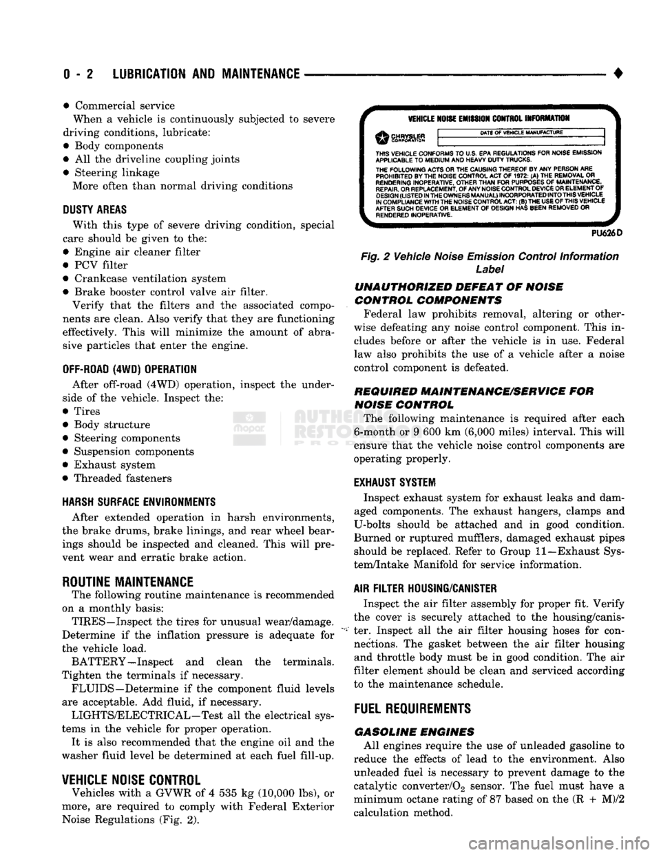
more, are required to comply with Federal Exterior Noise Regulations (Fig. 2).
VEHICLE
NOISE
EMISSION
CONTROL INFORMATION
DATE
OF
VEHICLE
MANUFACTURE
THIS
VEHICLE CONFORMS
TO
U.S. EPA REGULATIONS FOR NOISE EMISSION
APPLICABLE
TO
MEDIUM
AND HEAVY
DUTY
TRUCKS. THE
FOLLOWING
ACTS OR THE CAUSING THEREOF BY ANY PERSON ARE PROHIBITED BY THE NOISE CONTROL ACT
OF 1972. (A) THE
REMOVAL
OR
RENDERING
INOPERATIVE, OTHER
THAN
FOR
PURPOSES
OF
MAINTENANCE,
REPAIR.
OR REPLACEMENT, OF ANY NOISE CONTROL DEVICE OR ELEMENT OF
DESIGN
(LISTED
IN
THE
OWNERS
MANUAL)
INCORPORATED
INTO
THIS
VEHICLE
IN COMPLIANCE
WITH
THE NOISE CONTROL
ACT:
(B) THE
USE
OF
THIS
VEHICLE
AFTER SUCH DEVICE
OR
ELEMENT
OF
DESIGN HAS BEEN REMOVED
OR
RENDERED
INOPERATIVE.
PU626D
Fig.
2 Vehicle
Noise
Emission
Control Information
Label
UNAUTHORIZED
DEFEAT
OF
NOISE
CONTROL COMPONENTS
Federal law prohibits removal, altering or other
wise defeating any noise control component. This in
cludes before or after the vehicle is in use. Federal
law also prohibits the use of a vehicle after a noise
control component is defeated.
REQUIRED MAINTENANCE/SERVICE
FOR
NOISE
CONTROL
The following maintenance is required after each
6-month or 9 600 km (6,000 miles) interval. This will
ensure that the vehicle noise control components are
operating properly.
EXHAUST SYSTEM
Inspect exhaust system for exhaust leaks and dam
aged components. The exhaust hangers, clamps and
U-bolts should be attached and in good condition.
Burned or ruptured mufflers, damaged exhaust pipes should be replaced. Refer to Group 11—Exhaust Sys
tem/Intake Manifold for service information.
AIR
FILTER
HOUSING/CANISTER
Inspect the air filter assembly for proper fit. Verify
the cover is securely attached to the housing/canis
ter. Inspect all the air filter housing hoses for con nections. The gasket between the air filter housing and throttle body must be in good condition. The air
filter element should be clean and serviced according
to the maintenance schedule.
FUEL
REQUIREMENTS
GASOLINE
ENGINES
All engines require the use of unleaded gasoline to
reduce the effects of lead to the environment. Also unleaded fuel is necessary to prevent damage to the
catalytic converter/02 sensor. The fuel must have a
minimum octane rating of 87 based on the (R + M)/2
calculation method.
Page 28 of 1502
•
LUBRICATION AND MAINTENANCE
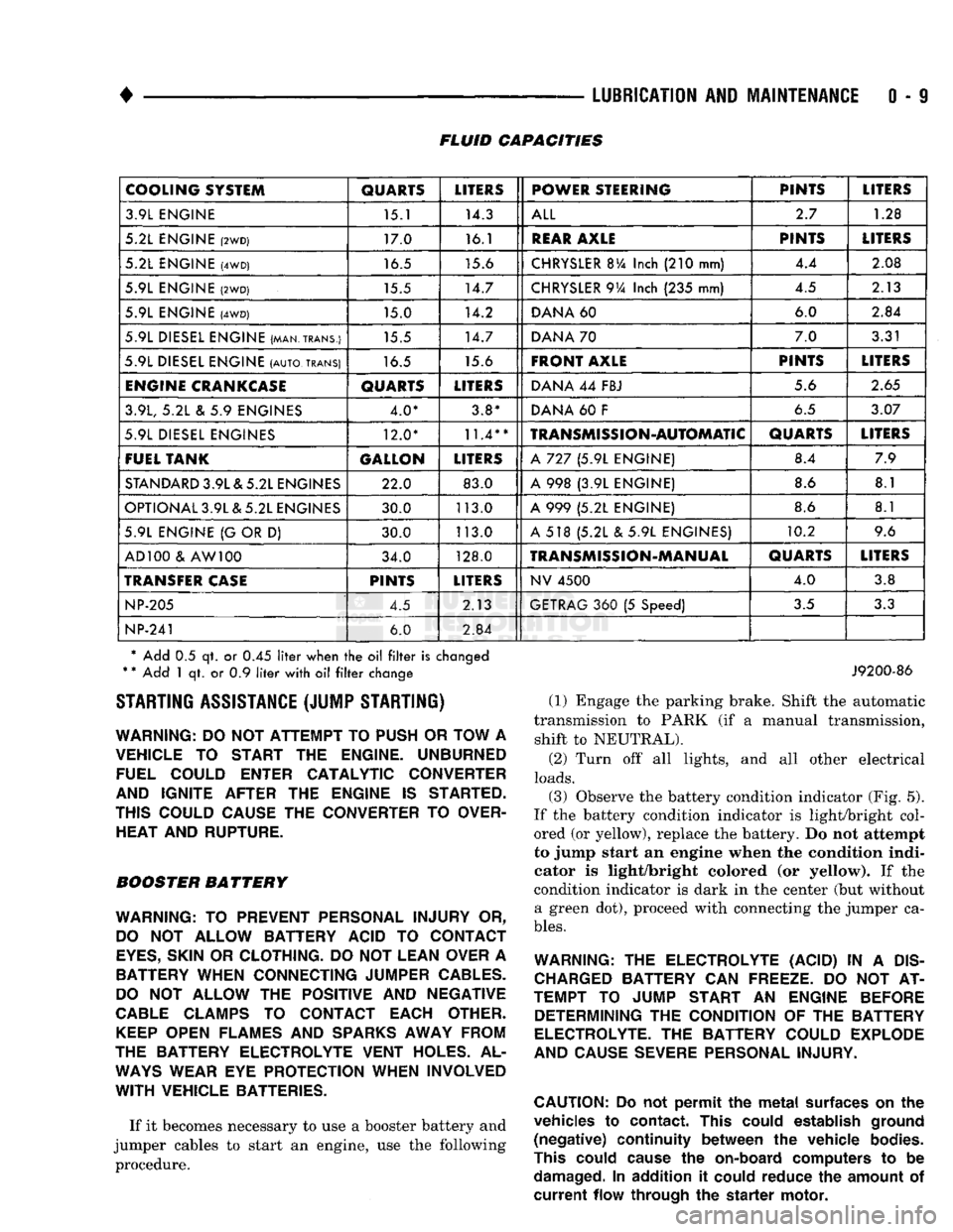
0 - 9 FLUID CAPACITIES
COOLING SYSTEM
QUARTS
LITERS
POWER STEERING PINTS
LITERS
3.9L ENGINE 15.1 14.3
ALL
2.7
1.28
5.2L ENGINE
(2WD)
17.0 16.1
REAR
AXLE
PINTS
LITERS
5.2L ENGINE
(4WD)
16.5 15.6
CHRYSLER
BVa
Inch
(210
mm) 4.4
2.08
5.9L ENGINE
(2WD)
15.5 14.7
CHRYSLER
9Va
Inch
(235
mm) 4.5
2.13
5.9L ENGINE
(4WD)
15.0 14.2
DANA
60 6.0
2.84
5.9L DIESEL ENGINE (MAN.TRANS.) 15.5 14.7
DANA
70 7.0
3.31
5.9L DIESEL ENGINE
(AUTO,
TRANS)
16.5 15.6
FRONT AXLE
PINTS
LITERS
ENGINE
CRANKCASE
QUARTS
LITERS
DANA
44
FBJ 5.6
2.65
3.9L,
5.2L & 5.9
ENGINES 4.0* 3.8*
DANA
60 F
6.5
3.07
5.9L DIESEL ENGINES 12.0*
11.4**
TRANSMISSION-AUTOMATIC
QUARTS
LITERS
FUEL TANK GALLON
LITERS
A
727 (5.9L
ENGINE) 8.4
7.9
STANDARD
3.9L & 5.2L ENGINES 22.0 83.0
A
998 (3.9L
ENGINE) 8.6
8.1
OPTIONAL 3.9L & 5.2L ENGINES 30.0 113.0
A
999 (5.2L
ENGINE) 8.6
8.1
5.9L ENGINE
{G
OR
D)
30.0 113.0
A
518 (5.2L & 5.9L
ENGINES) 10.2
9.6
AD 100
&
AW 100 34.0 128.0
TRANSMISSION-MANUAL
QUARTS
LITERS
TRANSFER
CASE
PINTS
LITERS
NV
4500
4.0
3.8
NP-205
4.5 2.13
GETRAG
360 (5
Speed)
3.5
3.3
NP-241
6.0
2.84
* Add
0.5 qt. or 0.45
liter
when
the oil filter
is
changed
*
*
Add
1 qt. or 0.9
liter
with
oil filter
change STARTING ASSISTANCE (JUMP STARTING)
WARNING:
DO NOT
ATTEMPT
TO
PUSH
OR
TOW
A
VEHICLE
TO
START
THE
ENGINE. UNBURNED FUEL COULD ENTER CATALYTIC CONVERTER
AND IGNITE AFTER
THE
ENGINE
IS
STARTED.
THIS COULD CAUSE
THE
CONVERTER
TO
OVER HEAT AND RUPTURE.
BOOSTER BATTERY
WARNING:
TO
PREVENT PERSONAL INJURY
OR,
DO
NOT
ALLOW BATTERY ACID
TO
CONTACT
EYES,
SKIN
OR
CLOTHING.
DO NOT
LEAN OVER
A
BATTERY WHEN CONNECTING JUMPER
CABLES.
DO
NOT
ALLOW
THE
POSITIVE
AND
NEGATIVE
CABLE
CLAMPS
TO
CONTACT EACH OTHER.
KEEP
OPEN FLAMES
AND
SPARKS
AWAY FROM
THE BATTERY ELECTROLYTE VENT HOLES.
AL
WAYS
WEAR
EYE
PROTECTION WHEN INVOLVED
WITH
VEHICLE BATTERIES.
If it becomes necessary to use a booster battery and
jumper cables to start an engine, use the following procedure.
J9200-86
(1) Engage the parking brake. Shift the automatic
transmission to PARK (if a manual transmission, shift to NEUTRAL).
(2) Turn off all lights, and all other electrical
loads.
(3)
Observe the battery condition indicator (Fig. 5).
If the battery condition indicator is light/bright col
ored (or yellow), replace the battery. Do not attempt
to jump start an engine when the condition indi
cator is light/bright colored (or yellow). If the
condition indicator is dark in the center (but without a green dot), proceed with connecting the jumper ca
bles.
WARNING:
THE
ELECTROLYTE (ACID)
IN A
DIS
CHARGED
BATTERY
CAN
FREEZE.
DO NOT AT
TEMPT
TO
JUMP START
AN
ENGINE BEFORE DETERMINING
THE
CONDITION
OF THE
BATTERY
ELECTROLYTE.
THE
BATTERY COULD EXPLODE
AND CAUSE SEVERE PERSONAL INJURY.
CAUTION:
Do not
permit
the
metal
surfaces
on the
vehicles
to
contact.
This
could
establish
ground
(negative)
continuity
between
the
vehicle
bodies.
This
could
cause
the
on-board
computers
to be
damaged.
In
addition
it
could
reduce
the
amount
of
current
flow
through
the
starter
motor.
Page 190 of 1502

•
BRAKES
i - 3 BRAKE DIAGNOSIS
INDEX
page
Brake
Warning Lights
3
Diagnosing
Brake Problems .................
4
Diagnosis
Procedures
3
Low
Vacuum
Switch—Diesel
Models
3
page
Master
Cylinder/Power Booster Test
5
Power
Booster
Check
Valve Test .............
6
Power
Booster
Vacuum
Test .................
6
Testing Diesel
Engine
Vacuum
Pump
Output
.... 6
DIAGNOSIS
PROCEDURES
Brake diagnosis involves determining
if the
prob
lem
is
related
to a
mechanical, hydraulic
or
vacuum
operated component.
A
preliminary check, road test
ing
and
component inspection
can all be
used
to de
termine
a
problem cause. Road testing will either verify proper brake opera
tion
or
confirm
the
existence
of a
problem. Compo nent inspection will,
in
most cases, identify
the
actual part causing
a
problem. The first diagnosis step
is the
preliminary check. This
involves inspecting fluid level, parking brake action,
wheel
and
tire condition, checking
for
obvious leaks
or
component damage
and
testing brake pedal response. A road test will confirm
the
existence
of a
problem.
Final diagnosis procedure involves road test analysis and
a
visual inspection
of
brake components.
BRAKE
WARNING LIGHTS
The
red
brake warning light
is
connected
to the
parking brake switch
and to the
pressure differential switch
in the
combination valve. The
red
light will illuminate when
the
parking
brakes
are
applied
or
when
a
fluid pressure drop
oc
curs
in the
front
or
rear brake circuit.
The
light will
also illuminate
for
approximately
2-4
seconds
at en
gine start
up.
This
is a
self test feature designed
to
check bulb
and
circuit operation each time
the en
gine
is
started. The amber antilock light
is
connected
to the
anti-
lock rear brake hydraulic valve.
The
light will illu
minate
if a
fault occurs within
the
antilock system.
LOW VACUUM SWITCH-DIESEL MODELS
On diesel models,
the red
brake warning light
is
also
used
to
alert
the
driver
of a low
brake booster vacuum
condition.
The
warning light
is in
circuit with
a
vacuum
warning switch mounted
on the
driver side fender
panel.
The
vacuum side
of the
switch
is
connected
to the
power brake booster.
The
electrical side
of the
switch
is
connected
to the
brake warning light. The
low
vacuum switch monitors booster vacuum
level whenever
the
engine
is
running.
If
booster vac
uum falls below
8.5
inches vacuum
for a
minimum
of
10 seconds,
the
switch completes
the
circuit
to the
warning light causing
it to
illuminate.
The
warning light
is
designed
to
differentiate between
a low
vac
uum condition
and a
hydraulic circuit fault.
PRELIMINARY
BRAKE CHECK
(1) Check condition
of
tires
and
wheels. Damaged
wheels
and
worn, damaged,
or
underinflated tires
can
cause pull, shudder, tramp,
and a
condition similar
to
grab.
(2)
If
complaint
was
based
on
noise when braking,
check suspension components. Jounce front
and
rear
of
vehicle
and
listen
for
noise that might
be
caused
by
loose, worn
or
damaged suspension
or
steering compo
nents.
(3) Inspect brake fluid level
and
condition. Note
that
the
front disc brake reservoir fluid level will drop
in
proportion
to
normal lining wear. Also note
that brake fluid tends
to
darken over time. This
is normal
and
should
not be
mistaken
for
con
tamination.
If the
fluid
is
still clear
and
free
of
foreign material,
it is OK.
(a)
If
fluid level
is
abnormally
low,
look
for
evi
dence
of
leaks
at
calipers, wheel cylinders, brake-
lines
and
master cylinder.
(b)
If
fluid appears contaminated, drain
out a
sample.
If
fluid
is
separated into layers,
or
obvi
ously contains
oil or a
substance other than brake
fluid,
the
system seals
and
cups will have
to be re
placed
and the
hydraulic system flushed.
(4) Check parking brake operation. Verify free
movement
and
full release
of
cables
and
pedal. Also
note
if
vehicle
was
being operated with parking
brake partially applied.
(5) Check brake pedal operation. Verify that pedal
does
not
bind
and has
adequate free play.
If
pedal
lacks free play, check pedal
and
power booster
for be
ing loose
or for
bind condition.
Do not
road test until
condition
is
corrected.
(6)
If
components checked appear
OK,
road test
the
vehicle.
ROAD
TESTING (1)
If
complaint involved
low
brake pedal, pump
the pedal
and
note
if the
pedal comes back
up to
nor mal height.
(2) Check brake pedal response with transmission
in Neutral
and
engine running. Pedal should remain
firm under steady foot pressure.
Page 196 of 1502
BRAKES
i - 9
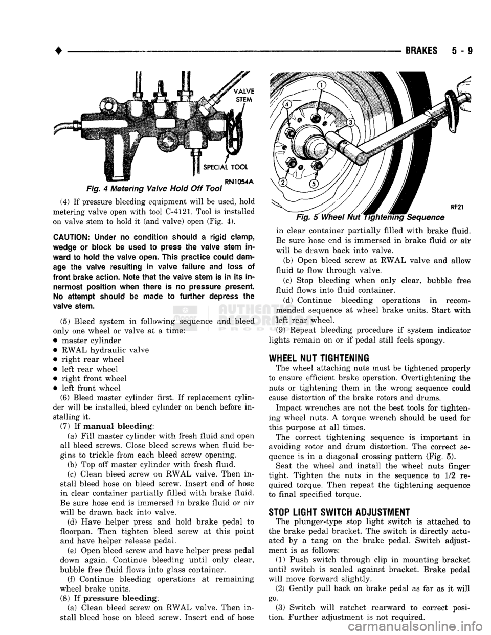
Fig.
4 Metering
Valve
Hold
Off Tool (4) If pressure bleeding equipment will be used, hold
metering valve open with tool C-4121. Tool is installed on valve stem to hold it (and valve) open (Fig. 4).
CAUTION:
Under
no
condition should
a
rigid clamp,
wedge
or
block
be
used
to
press
the
valve stem
in
ward
to
hold
the
valve open. This
practice
could dam
age
the
valve resulting
in
valve
failure and
loss
of
front
brake action. Note
that the
valve stem
is in its in
nermost position when
there
is no
pressure present.
No
attempt
should
be
made
to further
depress
the
valve stem.
(5) Bleed system in following sequence and bleed
only one wheel or valve at a time:
• master cylinder • RWAL hydraulic valve
• right rear wheel
• left rear wheel
• right front wheel • left front wheel (6) Bleed master cylinder first. If replacement cylin
der will be installed, bleed cylinder on bench before in stalling it.
(7) If manual bleeding: (a) Fill master cylinder with fresh fluid and open
all bleed screws. Close bleed screws when fluid be
gins to trickle from each bleed screw opening. (b) Top off master cylinder with fresh fluid.
(c) Clean bleed screw on RWAL valve. Then in
stall bleed hose on bleed screw. Insert end of hose
in clear container partially filled with brake fluid.
Be sure hose end is immersed in brake fluid or air
will be drawn back into valve.
(d) Have helper press and hold brake pedal to
floorpan. Then tighten bleed screw at this point and have helper release pedal.
(e) Open bleed screw and have helper press pedal
down again. Continue bleeding until only clear,
bubble free fluid flows into glass container. (f) Continue bleeding operations at remaining
wheel brake units.
(8) If pressure bleeding: (a) Clean bleed screw on RWAL valve. Then in
stall bleed hose on bleed screw. Insert end of hose in clear container partially filled with brake fluid.
Be sure hose end is immersed in brake fluid or air
will be drawn back into valve.
(b) Open bleed screw at RWAL valve and allow
fluid to flow through valve.
(c) Stop bleeding when only clear, bubble free
fluid flows into fluid container.
(d) Continue bleeding operations in recom
mended sequence at wheel brake units. Start with
left rear wheel.
(9) Repeat bleeding procedure if system indicator
lights remain on or if pedal still feels spongy.
WHEEL
NUT
TIGHTENING
The wheel attaching nuts must be tightened properly
to ensure efficient brake operation. Overtightening the nuts or tightening them in the wrong sequence could
cause distortion of the brake rotors and drums.
Impact wrenches are not the best tools for tighten
ing wheel nuts. A torque wrench should be used for
this purpose at all times.
The correct tightening sequence is important in
avoiding rotor and drum distortion. The correct se
quence is in a diagonal crossing pattern (Fig. 5). Seat the wheel and install the wheel nuts finger
tight. Tighten the nuts in the sequence to 1/2 re quired torque. Then repeat the tightening sequence
to final specified torque.
STOP
LIGHT SWITCH ADJUSTMENT
The plunger-type stop light switch is attached to
the brake pedal bracket. The switch is directly actu ated by a tang on the brake pedal. Switch adjust
ment is as follows: (1) Push switch through clip in mounting bracket
until switch is sealed against bracket. Brake pedal
will move forward slightly.
(2) Gently pull back on brake pedal as far as it will
go.
(3) Switch will ratchet rearward to correct posi
tion. Further adjustment is not required.
Page 325 of 1502
8A
- 4
ELECTRICAL
•
IGNITION
OFF
DRAW
(IOD)
Ignition off draw refers to power being drained
from the battery with the ignition turned off. A nor
mal vehicle electrical system will draw from 5 to 20
milliamps. A vehicle that has not been operated for
an extended period of time (approximately 20 days)
may discharge the battery to an inadequate level.
Battery drain should not exceed approximately 20
MA (20 milliamps = 0.020 amps). The 20 MA are needed to supply PCM memory,
digital clock memory, and ETR (electronically tuned
radio) memory. Excessive battery drain is caused by items left
turned on, internally shorted generator, or intermit
tent short in wiring.
If the IOD is excessive (over 20 milliamperes), the
defect must be found and corrected before replacing a
battery. In most cases the battery can be charged and returned to service.
TEST PROCEDURE Testing for higher amperage IOD must be per
formed first to prevent damage to most milliamp
meters.
Verify that all electrical accessories are OFF. Turn
off all lights, remove ignition key, and close all
doors.
If the vehicle is equipped with electronic acces
sories (illuminated entry, high line radio), allow the
systems to automatically shut off (time out), up to 3
minutes.
(1) After determining that the underhood lamp is
operating properly then disconnect bulb. (2) Disconnect negative cable from battery.
(3) Connect a typical 12 volt test light (low watt
age bulb) between the negative cable clamp and the
battery negative terminal. The test light may light brightly for up to 3 min
utes or may not light at all (depending on the elec
trical equipment). The term brightly being used
throughout the following tests, implies the bright ness of the test light will be the same as if it were
connected across the battery.
The test light must be securely clamped to the neg
ative cable and battery terminal. If the test light be
comes disconnected during any of the IOD test, the electronic timer function will be activated and all
tests must be repeated.
(4) After 3 minutes, the test light should turn OFF
or be DIMLY lit (depending on the electrical equip
ment).
If the test light remains brightly lit do not
disconnect it. Remove each fuse or circuit breaker (refer to Group 8 - Wiring Diagrams) until test light
is either OFF or DIMLY lit. This will eliminate the
higher amperage draw.
If test light is still bright after disconnecting each
fuse and circuit breaker, disconnect the wiring har ness from the generator. Refer to Generator Testing
in this group. Do not disconnect the test light. After higher amperage IOD has been corrected, low
amperage IOD may be checked.
It is now safe to install milliamp meter to check for
low amperage IOD.
(5) With test light still connected, securely clamp
an ammeter between battery negative terminal and
negative battery cable.
If the test light or the milliamp meter circuit is
broken the various timer circuits will start. Do
not open any doors or turn on any electrical ac cessories with the test light disconnected or the
meter may be damaged.
(6) Disconnect test light. The current draw should
not exceed 0.020 amp. If it exceeds 20 milliamps iso
late each circuit by removing circuit breakers and
fuses.
The meter reading drops once the high current
problem is found. Repair this section of the circuit,
whether it is a wiring short or component failure.
BATTERY
OPEN CIRCUIT VOLTAGE TEST
A battery voltage (no load) test will indicate the
state of charge of a battery that will pass the Battery
Load Test described in this section. Before proceed
ing with this test or the Battery Load Test the
battery must be completely charged as de scribed in Battery Charging in this section. If a battery has a no load voltage reading of 12.4
volts or greater but will not endure a load test, it is
defective and should be replaced. Refer to Group 8B,
Battery/Starter Service for instructions. To test bat
tery no load voltage, perform the following operation: (1) Before measuring open circuit voltage, the sur
face charge must be removed from plates. Turn head lights on for 15 seconds then allow up to 5 minutes
for voltage to stabilize. (2) Remove both battery cables, negative first.
(3) Using a voltmeter connected to the battery
posts,
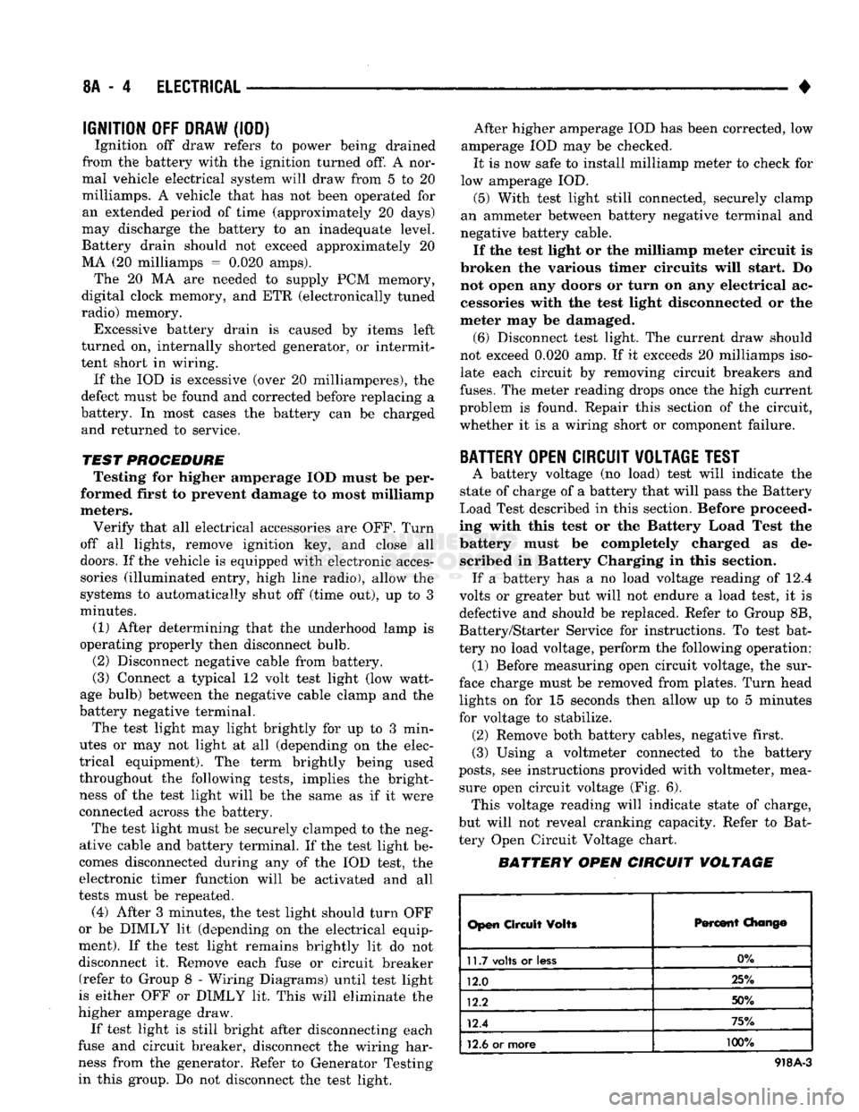
see instructions provided with voltmeter, mea sure open circuit voltage (Fig. 6). This voltage reading will indicate state of charge,
but will not reveal cranking capacity. Refer to Bat
tery Open Circuit Voltage chart.
BATTERY OPEN CIRCUIT VOLTAGE
Open
Circuit
Volts
Percent
Chang©
11.7
volts
or
less
0%
12.0 25%
12.2 50%
12.4 75%
12.6
or more 100%
918A-3
Page 330 of 1502
•
ELECTRICAL
8A - 9
ENGINE STARTER MOTOR TEST PROCEDURES
GENERAL INFORMATION
The starting system consists of an:
• ignition switch
• starter relay
• park/neutral position switch (automatic transmis sion)
• clutch switch (diesel engine-manual transmission)
• wiring harness
• battery
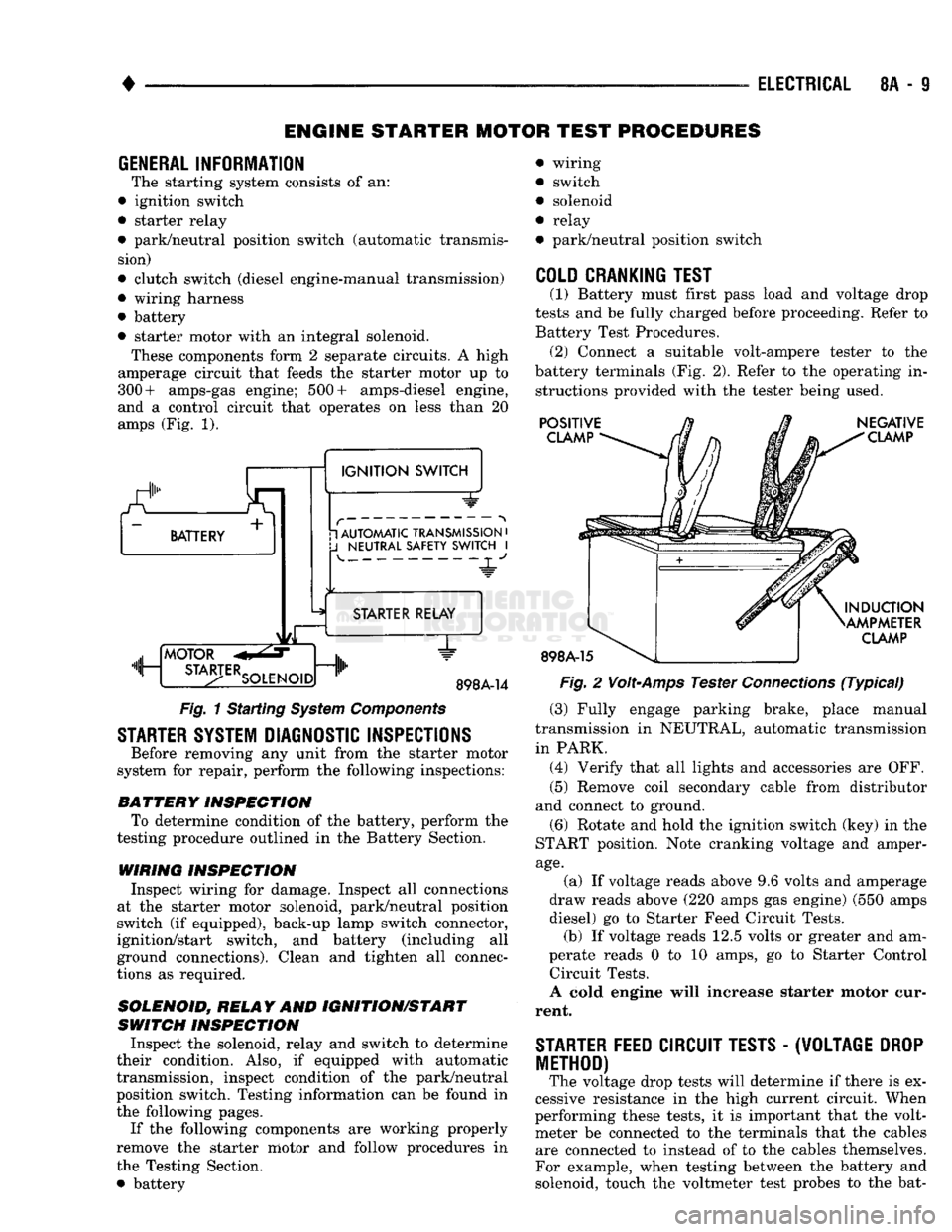
• starter motor with an integral solenoid. These components form 2 separate circuits. A high
amperage circuit that feeds the starter motor up to
300+ amps-gas engine; 500+ amps-diesel engine,
and a control circuit that operates on less than 20
amps (Fig. 1).
a.
BATTERY +
1
IGNITION
SWITCH 1 AUTOMATIC TRANSMISSION
•
J
NEUTRAL SAFETY SWITCH
I 4-
"JL"
MOTOR
m, ...
STA3-TERSOLENO,Dnlh
STARTER RELAY
1"
898A-14
Fig.
1 Starting
System
Components
STARTER SYSTEM DIAGNOSTIC INSPECTIONS
Before removing any unit from the starter motor
system for repair, perform the following inspections:
BATTERY
INSPECTION
To determine condition of the battery, perform the
testing procedure outlined in the Battery Section.
WIRING INSPECTION
Inspect wiring for damage. Inspect all connections
at the starter motor solenoid, park/neutral position
switch (if equipped), back-up lamp switch connector,
ignition/start switch, and battery (including all
ground connections). Clean and tighten all connec
tions as required.
SOLENOID, RELAY
AND
IGNITION/START
SWITCH
INSPECTION
Inspect the solenoid, relay and switch to determine
their condition. Also, if equipped with automatic
transmission, inspect condition of the park/neutral position switch. Testing information can be found in
the following pages.
If the following components are working properly
remove the starter motor and follow procedures in
the Testing Section. • battery wiring
switch
solenoid
relay
park/neutral position switch
COLD CRANKING TEST
(1) Battery must first pass load and voltage drop
tests and be fully charged before proceeding. Refer to Battery Test Procedures. (2) Connect a suitable volt-ampere tester to the
battery terminals (Fig. 2). Refer to the operating in structions provided with the tester being used.
POSITIVE
CLAMP
898A-15
NEGATIVE
CLAMP
INDUCTION
AMPMETER
CLAMP
Fig.
2
Volt-Amps
Tester
Connections
(Typical)
(3) Fully engage parking brake, place manual
transmission in NEUTRAL, automatic transmission
in PARK. (4) Verify that all lights and accessories are OFF. (5) Remove coil secondary cable from distributor
and connect to ground.
(6) Rotate and hold the ignition switch (key) in the
START position. Note cranking voltage and amper
age.
(a) If voltage reads above 9.6 volts and amperage
draw reads above (220 amps gas engine) (550 amps
diesel) go to Starter Feed Circuit Tests. (b) If voltage reads 12.5 volts or greater and am-
perate reads 0 to 10 amps, go to Starter Control Circuit Tests.
A cold engine will increase starter motor cur
rent.
STARTER
FEED
CIRCUIT TESTS
-
(W0LTAGE
DROP
METHOD)
The voltage drop tests will determine if there is ex
cessive resistance in the high current circuit. When
performing these tests, it is important that the volt meter be connected to the terminals that the cables are connected to instead of to the cables themselves.
For example, when testing between the battery and
solenoid, touch the voltmeter test probes to the bat-
Page 331 of 1502
8A
- 10
ELECTRICAL
•
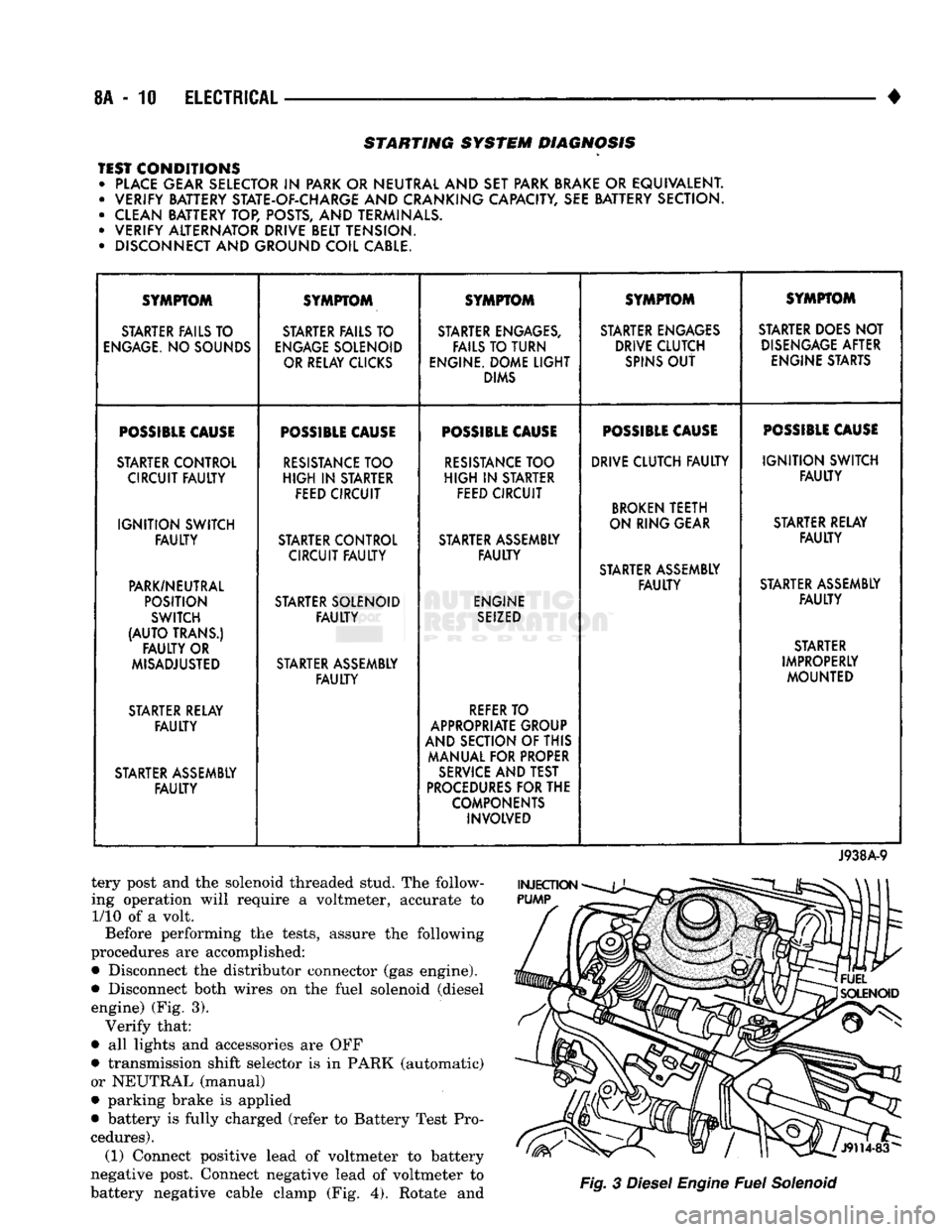
STARTING SYSTEM DIAGNOSIS
TEST CONDITIONS • PLACE GEAR SELECTOR
IN
PARK OR NEUTRAL AND SET PARK BRAKE
OR
EQUIVALENT. • VERIFY BATTERY STATE-OF-CHARGE AND CRANKING CAPACITY, SEE BATTERY SECTION.
• CLEAN BATTERY TOP, POSTS, AND TERMINALS.
• VERIFY ALTERNATOR DRIVE BELT TENSION.
• DISCONNECT AND GROUND COIL CABLE. SYMPTOM
SYMPTOM SYMPTOM SYMPTOM SYMPTOM
STARTER FAILS TO STARTER FAILS TO STARTER ENGAGES, STARTER ENGAGES STARTER DOES NOT
ENGAGE.
NO SOUNDS
ENGAGE
SOLENOID FAILS TO TURN DRIVE CLUTCH
DISENGAGE
AFTER
OR RELAY CLICKS ENGINE. DOME
LIGHT
SPINS
OUT
ENGINE STARTS
DIMS
POSSIBLE
CAUSE
POSSIBLE
CAUSE
POSSIBLE
CAUSE
POSSIBLE
CAUSE
POSSIBLE
CAUSE
STARTER CONTROL
RESISTANCE
TOO
RESISTANCE
TOO DRIVE CLUTCH
FAULTY
IGNITION
SWITCH
CIRCUIT
FAULTY
HIGH
IN
STARTER
HIGH
IN
STARTER
FAULTY
FEED CIRCUIT FEED CIRCUIT
BROKEN
TEETH
IGNITION
SWITCH ON RING GEAR
STARTER RELAY
FAULTY
STARTER CONTROL STARTER ASSEMBLY
FAULTY
CIRCUIT
FAULTY FAULTY
STARTER ASSEMBLY
PARK/NEUTRAL
FAULTY
STARTER ASSEMBLY
POSITION STARTER SOLENOID ENGINE
FAULTY
SWITCH
FAULTY
SEIZED
(AUTO
TRANS.) STARTER
FAULTY
OR STARTER
MISADJUSTED STARTER ASSEMBLY IMPROPERLY
FAULTY
MOUNTED
STARTER RELAY
REFER
TO
FAULTY
APPROPRIATE GROUP
AND SECTION OF THIS
MANUAL FOR PROPER
STARTER ASSEMBLY
SERVICE
AND TEST
FAULTY
PROCEDURES
FOR THE
COMPONENTS INVOLVED
J938A-9
tery post and the solenoid threaded stud. The follow
ing operation will require a voltmeter, accurate to 1/10 of a volt.
Before performing the tests, assure the following
procedures are accomplished:
•
Disconnect the distributor connector (gas engine).
•
Disconnect both wires on the fuel solenoid (diesel engine) (Fig. 3). Verify that:
•
all lights and accessories are OFF
•
transmission shift selector is in PARK (automatic)
or NEUTRAL (manual)
•
parking brake is applied
•
battery is fully charged (refer to Battery Test Pro
cedures). (1) Connect positive lead of voltmeter to battery
negative post. Connect negative lead of voltmeter to
battery negative cable clamp (Fig. 4). Rotate and
Fig.
3
Diesel
Engine
Fuel
Solenoid