1993 DODGE TRUCK coolant capacity
[x] Cancel search: coolant capacityPage 272 of 1502
COOLING SYSTEM
CONTENTS page
DIAGNOSIS
... 4
ENGINE
ACCESSORY
DRIVE BELTS
40
ENGINE
BLOCK HEATERS
48
GENERAL
INFORMATION
Throughout this group, references are made to partic
ular vehicle models by alphabetical designation or by
the particular vehicle nameplate. A chart showing a
breakdown of alphabetical designations is included in
the Introduction section at the beginning of this man
ual.
5.9L gas powered engines will be' referred to as ei
ther: LDC (Light Duty Cycle) or HDC (Heavy Duty
Cycle).
COOLING
SYSTEM
The cooling system regulates engine operating tem
perature. It allows the engine to reach normal oper-
page
SERVICE
PROCEDURES
15
SPECIFICATIONS
; 49
ating temperature as quickly as possible. It also
maintains normal operating temperature and pre
vents overheating.
The cooling system also provides a means of heat
ing the passenger compartment and cooling the auto
matic transmission fluid (if equipped). The cooling system is pressurized and uses a centrifugal water
pump to circulate coolant throughout the system.
An optional factory installed maximum duty cool
ing package is available on most models. This pack age will provide additional cooling capacity for
vehicles used under extreme conditions such as
trailer towing in high ambient temperatures.
NOTE: HEATER
COOLANT FLOW
CIRCUIT
IS
ALWAYS
OPEN
EXCEPT
WHEN
IN MAX. A/C
OR
OFF
MODES
HEATER
INTAKE MANIFOLD
COOLANT FLOW "METERED" FROM REAR
TO
FRONT
AND
BELOW EXHAUST
HEAT
CROSSOVER
SHUT
OFF
VALVE
A/C
ONLY COOLANT FLOW
-
PUMP
TO
CYLINDER BLOCK,
UP
THROUGH CYLINDER HEADS
TO
INTAKE MANIFOLD WATER
BOX TO
RADIATOR-TO PUMP
•BYPASS
THERMOSTAT CLOSED-HIGH FLOW
THERMOSTAT OPEN
- LOW
FLOW
J9207-18
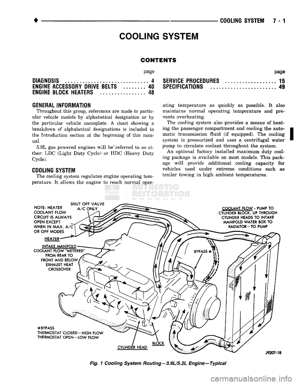
Fig.
1
Cooling
System
Routing—3.9U5.2L Engine—Typical
Page 302 of 1502
•
COOLING
SYSTEM
7 - 31 It utilizes thermal expansion and contraction of cool
ant to keep coolant free of trapped air. It provides a
volume for expansion and contraction of coolant. It
also provides a convenient and safe method for
checking coolant level and adjusting level at atmo
spheric pressure. This is done without removing ra
diator pressure cap. It also provides some reserve
coolant to cover minor leaks and evaporation or boil
ing losses.
FAN
SHROUD
J9107-67
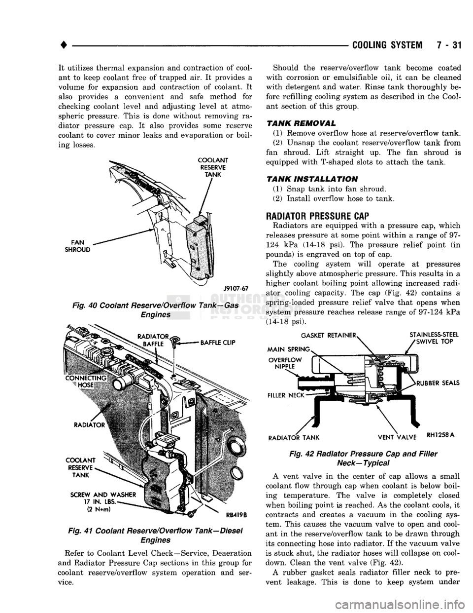
Fig.
40 Coolant Reserve/Overflow Tank—Gas
Engines
Fig.
41 Coolant Reserve/Overflow Tank—Diesel
Engines
Refer to Coolant Level Check—Service, Deaeration
and Radiator Pressure Cap sections in this group for
coolant reserve/overflow system operation and ser
vice.
Should the reserve/overflow tank become coated
with corrosion or emulsifiable oil, it can be cleaned
with detergent and water. Rinse tank thoroughly be
fore refilling cooling system as described in the Cool ant section of this group.
TANK REMOVAL
(1) Remove overflow hose at reserve/overflow tank.
(2) Unsnap the coolant reserve/overflow tank from
fan shroud. Lift straight up. The fan shroud is
equipped with T-shaped slots to attach the tank.
TANK INSTALLATION
(1) Snap tank into fan shroud.
(2) Install overflow hose to tank.
RADIATOR
PRESSURE
CAP
Radiators are equipped with a pressure cap, which
releases pressure at some point within a range of 97- 124 kPa (14-18 psi). The pressure relief point (in
pounds) is engraved on top of cap. The cooling system will operate at pressures
slightly above atmospheric pressure. This results in a
higher coolant boiling point allowing increased radi ator cooling capacity. The cap (Fig. 42) contains a
spring-loaded pressure relief valve that opens when
system pressure reaches release range of 97-124 kPa (14-18 psi).
Fig.
42 Radiator
Pressure
Cap and
Filler
Neck—Typical
A vent valve in the center of cap allows a small
coolant flow through cap when coolant is below boil
ing temperature. The valve is completely closed
when boiling point is reached. As the coolant cools, it contracts and creates a vacuum in the cooling sys
tem. This causes the vacuum valve to open and cool ant in the reserve/overflow tank to be drawn through
its connecting hose into radiator. If the vacuum valve
is stuck shut, the radiator hoses will collapse on cool-
down. Clean the vent valve (Fig. 42).
A rubber gasket seals radiator filler neck to pre
vent leakage. This is done to keep system under
Page 751 of 1502
9
- 148 5.9L
(DIESEL) ENGINE
• Make sure the idler gear pin is installed in the lo
cating bore in the cylinder block. (2) Install the pump. Tighten the oil pump mount
ing bolts in two steps and in the sequence shown (Fig. 2).
• Step
1—Tighten
to 5 N«m (44 in. lbs.) torque.
• Step 2-Tighten to 24 N*m (18 ft. lbs.) torque. (3) The back plate on the pump seats against the
bottom of the bore in the cylinder block. When the
pump is correctly installed, the flange on the pump will not touch the cylinder block.
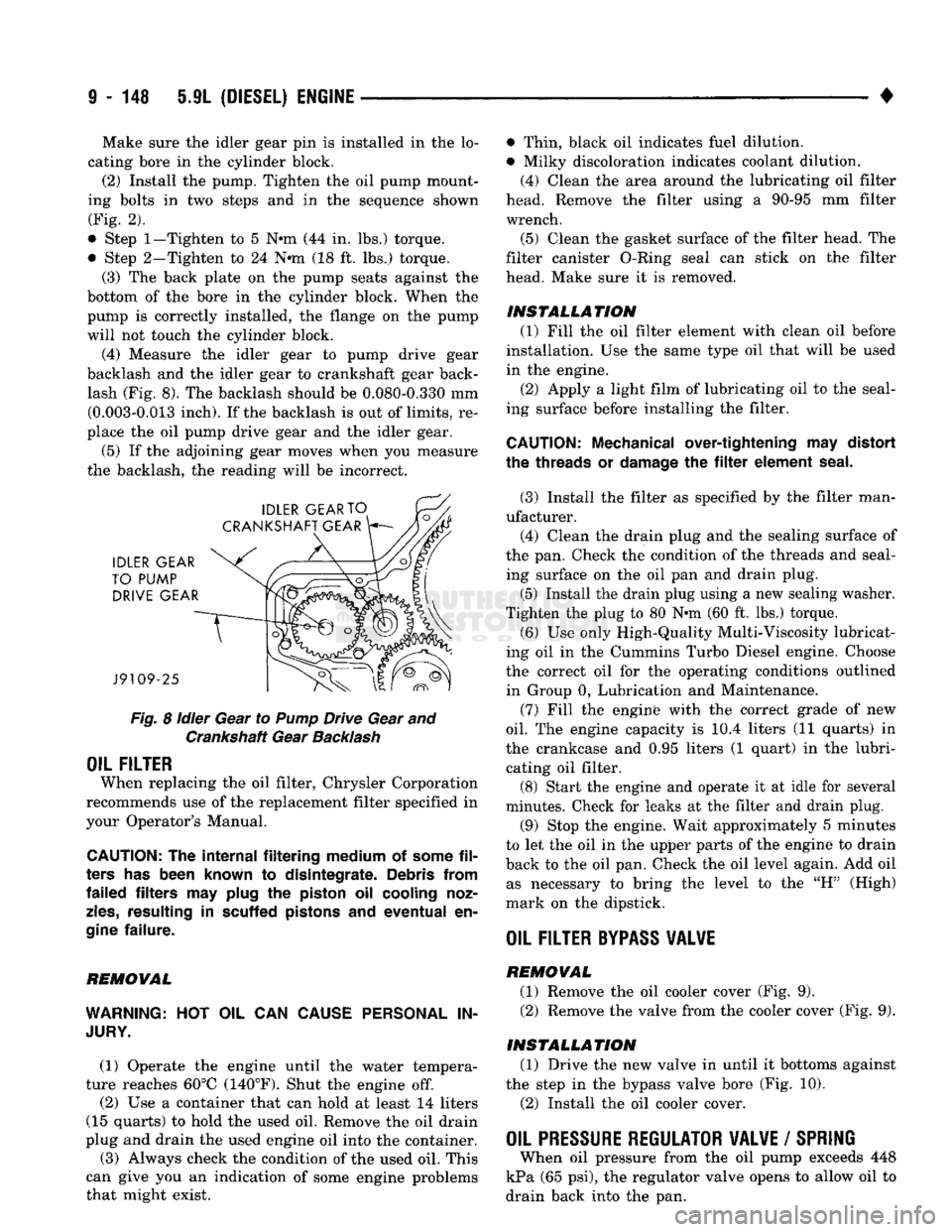
(4) Measure the idler gear to pump drive gear
backlash and the idler gear to crankshaft gear back lash (Fig. 8). The backlash should be 0.080-0.330 mm (0.003-0.013 inch). If the backlash is out of limits, re
place the oil pump drive gear and the idler gear.
(5) If the adjoining gear moves when you measure
the backlash, the reading will be incorrect.
Fig.
8
idler
Gear to
Pump
Drive Gear and Crankshaft Gear
Backlash
OIL FILTER
When replacing the oil filter, Chrysler Corporation
recommends use of the replacement filter specified in
your Operator's Manual.
CAUTION:
The
internal filtering medium
of
some
fil
ters
has
been known
to
disintegrate. Debris from
failed filters
may
plug
the
piston
oil
cooling noz
zles,
resulting
in
scuffed pistons
and
eventual
en
gine
failure.
REMOVAL
WARNING:
HOT OIL CAN
CAUSE PERSONAL
IN
JURY.
(1) Operate the engine until the water tempera
ture reaches 60°C (140°F). Shut the engine off.
(2) Use a container that can hold at least 14 liters
(15 quarts) to hold the used oil. Remove the oil drain
plug and drain the used engine oil into the container.
(3) Always check the condition of the used oil. This
can give you an indication of some engine problems
that might exist. • Thin, black oil indicates fuel dilution.
• Milky discoloration indicates coolant dilution.
(4) Clean the area around the lubricating oil filter
head. Remove the filter using a 90-95 mm filter
wrench.
(5) Clean the gasket surface of the filter head. The
filter canister O-Ring seal can stick on the filter
head. Make sure it is removed.
INSTALLATION (1) Fill the oil filter element with clean oil before
installation. Use the same type oil that will be used
in the engine.
(2) Apply a light film of lubricating oil to the seal
ing surface before installing the filter.
CAUTION:
Mechanical over-tightening
may
distort
the threads
or
damage
the filter
element seal.
(3) Install the filter as specified by the filter man
ufacturer. (4) Clean the drain plug and the sealing surface of
the pan. Check the condition of the threads and seal ing surface on the oil pan and drain plug.
(5) Install the drain plug using a new sealing washer.
Tighten the plug to 80 N-m (60 ft. lbs.) torque.
(6) Use only High-Quality Multi-Viscosity lubricat
ing oil in the Cummins Turbo Diesel engine. Choose
the correct oil for the operating conditions outlined in Group 0, Lubrication and Maintenance.
(7) Fill the enginfe with the correct grade of new
oil.
The engine capacity is i0.4 liters (11 quarts) in
the crankcase and 0.95 liters (1 quart) in the lubri cating oil filter. (8) Start the engine and operate it at idle for several
minutes. Check for leaks at the filter and drain plug.
(9) Stop the engine. Wait approximately 5 minutes
to let the oil in the upper parts of the engine to drain
back to the oil pan. Check the oil level again. Add oil as necessary to bring the level to the "H" (High)
mark on the dipstick.
OIL FILTER
BYPASS
VALWE
REMOVAL
(1) Remove the oil cooler cover (Fig. 9). (2) Remove the valve from the cooler cover (Fig. 9).
INSTALLATION (1) Drive the new valve in until it bottoms against
the step in the bypass valve bore (Fig. 10).
(2) Install the oil cooler cover.
OIL PRESSURE REGULATOR VALVE
/
SPRING
When oil pressure from the oil pump exceeds 448
kPa (65 psi), the regulator valve opens to allow oil to
drain back into the pan.
Page 1084 of 1502
•
AUTOMATIC TRANSiISSIO|-32RH/8iRH/37RH/42RH/4iRH
21 - 83 plate. The overdrive clutch also disengages the direct
clutch during 3-4 upshifts. As fluid pressure extends
the overdrive piston, the piston contacts the direct clutch hub pressing it rearward. This action com
presses the direct clutch spring relieving spring load on the clutch pack. The clutch is disengaged once
spring load is relieved.
The 3-4 accumulator cushions overdrive clutch en
gagement to smooth the transition into fourth gear.
The accumulator is charged at the same time as ap
ply pressure acts against the overdrive piston.
Converter clutch engagement in overdrive fourth
gear is controlled by sensor inputs to the powertrain
control module. In third gear above 25 mph, sensor inputs to the control module that determine clutch
engagement and shift timing are:
• coolant temperature (verifies minimum of 60° F)
• engine speed • vehicle speed
• throttle position
• manifold vacuum (MAP sensor)
Gearshift
Mechanism
The gear shift mechanism provides the same shift
positions used with 3-speed Chrysler transmissions
(P-R-N-D-2-1).
The shift into overdrive fourth gear range occurs
only after the transmission has completed the shift into D third gear range. No further movement of the
shift mechanism is required to complete the 3-4 shift.
The fourth gear upshift occurs automatically when
the overdrive control switch is in the ON position. Shift timing is determined by sensor inputs to the
engine controller.
Overdrive Control
Switch
The overdrive control switch is located in the in
strument panel. In the On position, automatic shifts
into fourth gear overdrive will occur. In the Off posi
tion, the switch overrides the engine controller pre
venting a shift to overdrive fourth gear range.
The switch has an indicator light that illuminates
when overdrive is turned off. The switch also resets
when the ignition key is turned to the OFF position so that the automatic overdrive feature is restored.
The use of fault codes is employed to help diagnose
the electronic components that operate the overdrive
unit and converter clutch.
HYDRAULIC
CONTROLS
The 42REJ/46RH hydraulic control system provides
fully automatic operation. The system performs five
basic functions which are: pressure supply, pressure regulation, flow control, clutch/band application, and
lubrication. 42RH/46RH system operation is similar to that de
scribed in the 32RH/36RH/37RH General Informa tion section. The main difference being fourth gear
operation which is covered here.
Pressure
Regulation
The pressure regulator valve maintains line pres
sure.
The amount of pressure developed is controlled
by throttle pressure which is dependent on the de gree of throttle opening. The regulator valve is lo
cated in the valve body.
The throttle valve determines line pressure and
shift speed. Governor pressure increases in propor
tion to vehicle speed. The throttle valve controls up shift and downshift speeds by regulating pressure
according to throttle position.
Flow
Control And Lubrication The manual valve is operated by the gearshift link
age and provides the operating range selected by the
driver.
The 1-2 shift valve provides 1-2 or 2-1 shifts and
the 2-3 shift valve provides 2-3 or 3-2 shifts.
The kickdown valve provides forced 3-2 or 3-1
downshifts depending on vehicle speed. Downshifts
occur when the throttle is opened beyond downshift
detent position which is just before wide open throt
tle.
The 2-3 valve throttle pressure plug provides 3-2
downshifts at varying throttle openings depending on
vehicle speed.
The 1-2 shift control valve transmits 1-2 shift pres
sure to the accumulator piston. This controls kick-
down band capacity on 1-2 upshifts and 3-2 downshifts.
The 3-4 shift valve, shuttle valve, timing valve and
accumulator are only actuated when the overdrive
solenoid is energized.
The solenoid contains a check ball that controls a
vent port to the 3-4 valve. The check ball either di
verts line pressure away from or directly to, the 3-4 shift valve. Energizing the solenoid causes the check
ball to close the vent port allowing line pressure to act upon the 3-4 upshift valve.
The limit valve determines maximum speed at
which a 3-2 part throttle kickdown can be made. Some transmissions do not have the limit valve and
maximum speed for a 3-2 kickdown is at the detent
position.
The 2-3 shuttle valve has two functions. First is
fast front band release and smooth engagement dur ing lift-foot 2-3 upshifts. The second is to regulate
front clutch and band application during 3-2 down
shifts.
The 3-4 shuttle valve uses a combination of throt
tle and governor pressure to control the rate of over
drive piston apply and release. This is done to
maintain shift quality at varying throttle openings.
Page 1104 of 1502
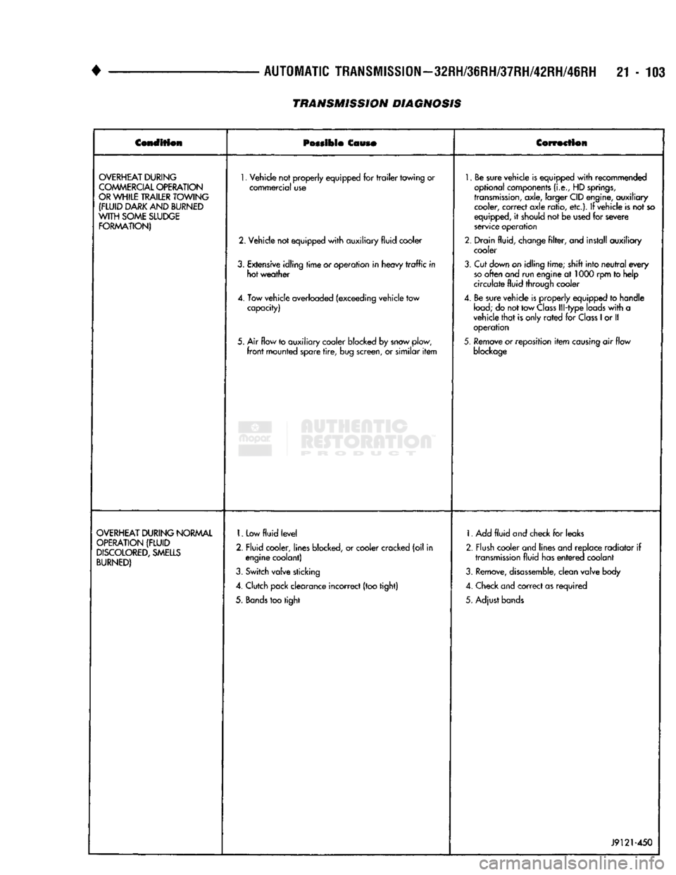
•
AUTOMATIC
TRANSMISSION—32RH/36RH/37RH/42RH/46RH
21-103
TRANSMISSION DIAGNOSIS
Condition
Possible
Couso
Correction
OVERHEAT
DURING
COMMERCIAL
OPERATION
OR
WHILE
TRAILER
TOWING
(FLUID
DARK
AND
BURNED
WITH
SOME
SLUDGE
FORMATION)
1.
Vehicle not properly equipped for
trailer
towing or
commercial use
2. Vehicle not equipped
with
auxiliary fluid cooler
3.
Extensive idling
time
or operation in heavy
traffic
in hot weather
4. Tow vehicle overloaded (exceeding vehicle tow capacity)
5. Air flow to auxiliary cooler blocked by snow plow,
front
mounted spare
tire,
bug screen, or similar
item
1.
Be sure vehicle is equipped
with
recommended
optional components
(i.e.,
HD
springs,
transmission,
axle, larger CID engine, auxiliary cooler, correct axle ratio, etc.). If vehicle is not so
equipped, it should not be used for severe
service operation
2. Drain fluid, change
filter,
and install auxiliary cooler
3.
Cut down on idling time; shift into
neutral
every
so
often and run engine at 1000 rpm to help
circulate fluid through cooler
4. Be sure vehicle is properly equipped to handle
load;
do not tow
Class
Ill-type loads
with
a
vehicle
that
is only
rated
for
Class
1
or II operation
5.
Remove or reposition
item
causing
air flow
blockage
OVERHEAT
DURING
NORMAL
OPERATION
(FLUID
DISCOLORED,
SMELLS
BURNED)
1.
Low
fluid
level
2. Fluid cooler, lines blocked, or cooler cracked (oil in engine coolant)
3.
Switch valve sticking
4. Clutch pack clearance incorrect (too tight)
5.
Bands
too tight 1. Add
fluid
and check for leaks
2. Flush cooler and lines and replace radiator if
transmission
fluid has
entered
coolant
3.
Remove,
disassemble,
clean valve body
4. Check and correct as required
5. Adjust bands
J9121-450
Page 1105 of 1502
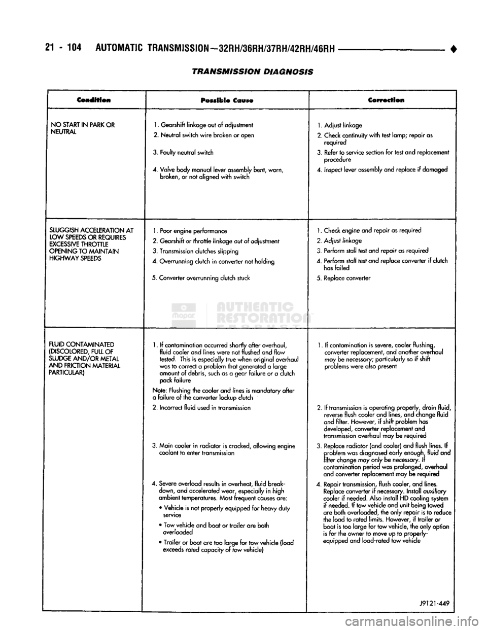
21 - 104
AUTOMATIC
TRANSMISSION—32RH/36RH/37RH/42RH/46RH
•
Condition
POMIOSO
Ccwse
Correction
NO
START
IN
PARK
OR
NEUTRAL
1.
Gearshift
linkage
out
of
adjustment
2.
Neutral
switch
wire
broken
or
open
3.
Faulty
neutral
switch
4.
Valve
body
manual
lever
assembly
bent,
worn,
broken,
or not
aligned
with
switch
1.
Adjust linkage
2.
Check continuity
with
test lamp; repair as required
3.
Refer to service section for test and replacement procedure
4.
inspect lever
assembly
and replace if damaged
SLUGGISH
ACCELERATION
AT
LOW
SPEEDS
OR
REQUIRES
EXCESSIVE
THROTTLE
OPENING
TO MAINTAIN
HIGHWAY
SPEEDS
1.
Poor
engine
performance
2.
Gearshift
or
throttle
linkage
out of adjustment
3.
Transmission
clutches slipping
4.
Overrunning clutch in converter not holding
5. Converter overrunning clutch stuck
1.
Check engine and repair as required
2. Adjust linkage
3. Perform stall test and repair as required
4.
Perform stall test and replace converter if clutch
has
failed
5. Replace converter
FLUID
CONTAMINATED
(DISCOLORED,
FULL
OF
SLUDGE
AND/OR
METAL
AND
FRICTION
MATERIAL
PARTICULAR)
1.
If contamination occurred shortly
after
overhaul,
fluid cooler and
lines
were
not
flushed
and flow rested. This is especially
true
when original overhaul
was
to correct a problem
that
generated a large
amount of debris,
such
as a gear
failure
or a clutch
pack
failure
Note: Flushing the cooler and lines is mandatory
after
a
failure
of the converter lockup clutch
2.
Incorrect fluid used in transmission
3. Main cooler in radiator is cracked, allowing engine coolant to
enter
transmission
4.
Severe overload results in overheat, fluid break
down,
and accelerated wear, especially in high
ambient temperatures.
Most
frequent
causes
are:
• Vehicle is not properly equipped for heavy duty
service
• Tow vehicle and boat or
trailer
are both overloaded
•
Trailer
or boat are too large for tow vehicle (load exceeds rated capacity of tow vehicle)
1.
If contamination is severe, cooler flushing,
converter replacement, and another overhaul may be
necessary;
particularly so if shift
problems
were
also
present
2.
If
transmission
is operating properly, drain fluid, reverse flush cooler and lines, and change fluid
and
filter.
However, if shift problem has
developed, converter replacement and
transmission
overhaul may be required
3.
Replace radiator (and cooler) and flush lines. If problem was
diagnosed
early
enough,
fluid and
filter
change
may
only
be
necessary.
If
contamination perioa was prolonged, overhaul
and
converter replacement may be required
4.
Repair
transmission,
flush cooler, and lines.
Replace
converter if
necessary.
Install auxiliary
cooler if needed.
Also
install HD cooling system if needed. If tow vehicle and unit being towed
are both overloaded, the only repair is to reduce
the load to
rated
limits. However, if
trailer
or boat is too large for tow vehicle, the only option
is
for the owner to move up to properly-
equipped and load-rated tow vehicle
J9121-449
TRANSMISSION DIAGNOSIS