1993 DODGE TRUCK turn signal
[x] Cancel search: turn signalPage 15 of 1502
10 INTRODUCTION
•
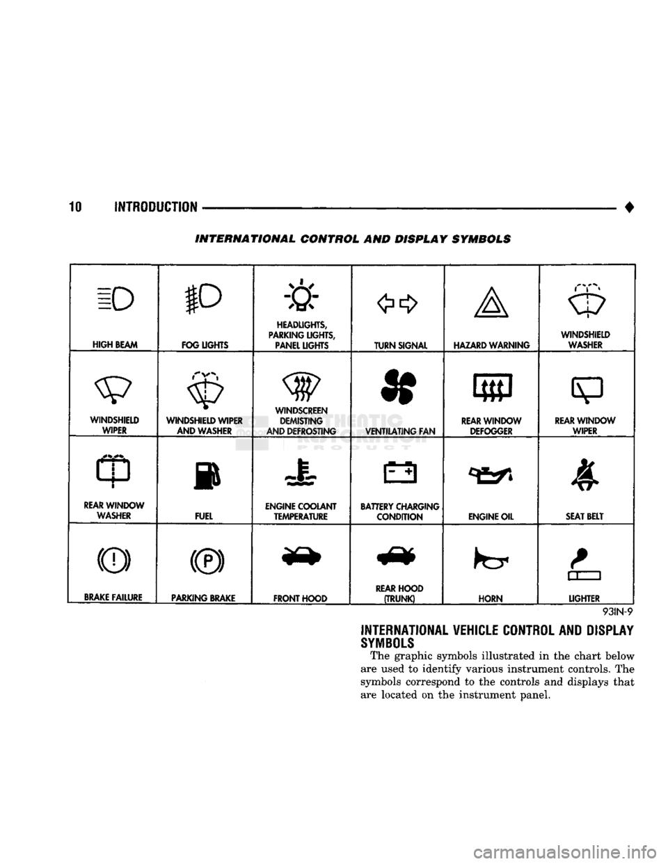
INTERNATIONAL CONTROL AND DISPLAY SYMBOLS
ID
HIGH
BEAM P
FOG UGHTS -&
HEADLIGHTS,
PARKING UGHTS, PANEL UGHTS TURN SIGNAL A
HAZARD WARNING WINDSHIELD
WASHER
WINDSHIELD WIPER WINDSHIELD WIPER
AND WASHER
AND DEFROSTING *
VENTILATING
FAN 8
M f
REAR
WINDOW DEFOGGER
sp
REARWINLX)W WIPER
CD
l
m
REAR
WINDOW WASHER FUEL ENGINE COOLANT
TEMPERATURE BATTERY CHARGING
CONDITION ENGINE OIL
SEAT
BELT
(©) (®) ky
11 J
LIGHTER
BRAKE
FAILURE
PARKING
BRAKE
FRONT HOOD
REAR
HOOD
(TRUNK)
HORN
11 J
LIGHTER
93IN-9
INTERNATIONAL VEHICLE CONTROL AND DISPLAY
SYMBOLS
The graphic symbols illustrated in the chart below
are used to identify various instrument controls. The
symbols correspond to the controls and displays that are located on the instrument panel.
Page 31 of 1502

0 - 12
LUBRICATION
AND
MAINTENANCE
• A vehicle equipped with SAE approved sling-type
towing equipment can be used (Fig. 10). However,
many vehicles are equipped with air dams, spoilers, and/or ground effect panels. In this case a wheel-lift
towing vehicle or a flat-bed hauling vehicle is recom mended (Fig. 10). If a flat bed device is used, the ap
proach angle should not exceed 15 degrees.
GROUND CLEARANCE The lifted wheels of the disabled vehicle should be
a minimum of 10 cm (4 in.) off the ground. Make
sure there is enough clearance at the opposite end.
This is critical when towing over rough terrain. If necessary, the rear ground clearance can be increased by removing the wheels from the lifted end
and then towing with the lifted end closer to the
ground. If the rear wheels are removed, secure the
brake drums. A 20 cm (8 in.) ground clearance must
be maintained between brake drums or rotors and the ground.
SAFETY PRECAUTIONS The following safety precautions must be consid
ered when preparing for and during a vehicle towing operation:
• Remove exhaust pipe tips that interfere with the
tow sling and crossbar • Padding should be placed between the tow sling/
crossbar and any painted surfaces
• If the vehicle is damaged, secure the loose and pro
truding parts
• Always use a safety chain system that is indepen dent of the lifting and towing equipment
• When placing tow hooks on the rear axle, position them so they do not damage the brake tubing or
hoses
• Do not allow any of the towing equipment to con
tact the fuel tank
• Do not tow the vehicle by connecting to the front
or rear shock absorbers
• The operator should not go under a vehicle while
it is lifted by the towing equipment. The vehicle
should first be supported by safety stands
• Do not allow passengers in a vehicle being towed
• Observe all state and local laws involving warning signals, night illumination, speed, etc.
• Do not exceed a towing speed of 48 km/h (30 mph)
• Avoid towing distances of more than 24 km (15
miles) whenever possible • Do not attach tow chains or a tow sling to a
bumper, the steering linkage, the universal joints, or a drive shaft
REAR-END RAISED TOWING It is recommended that the rear-end raised towing
method be used. Vehicles can be towed with the front
wheels on the ground for extended distances at speeds not exceeding 48 km/h (30 mph) (Fig. 11). (1) Attach the J-hooks around the axle shaft tubes
outboard of the rear springs. (2) Position and center the sling under and for
ward of the rear bumper. (3) Attach safety chains (with pads) at each end of
the rear bumper.
(4) Turn the ignition switch to the OFF position to
unlock the steering wheel. (5) Clamp the steering wheel with the front wheels
in the straight ahead position.
CAUTION:
Do not use the steering
column
lock
to
secure
front
wheel
in the straight-ahead
position.
(6) Shift the transmission to NEUTRAL.
POSITION CENTER BAR FORWARD
OF
BUMPER
-
/
J-HOOKS OUTBOARD
OF
SPRINGS
RN967A
Fig. 11 Rear-End
Raised
Towing
FRONT'END RAISED TOWING If a vehicle cannot be towed from the rear, the
front-end raised towing method normally can be
used (Fig. 12). (1) Center the sling with the bumper and position
it at the frame front crossmember.
CAUTION:
Use tow
chains
with
J-hooks
for
con
necting
to the
disabled
vehicle's
lower
suspension
arms.
Never use
T-hooks.
(2) Route the J-hooks and tow chains over the
steering linkage outboard of the coil spring.
(3) Attach the J-hooks to the outer end of the
lower suspension arms.
(4) Raise the vehicle.
(5.) Attach the safety chains to the disabled vehicle
at the frame rails.
Vehicles equipped with a MANUAL TRANSMIS
SION can be towed with the rear wheels on the
Page 247 of 1502
5
- 60
BRAKES
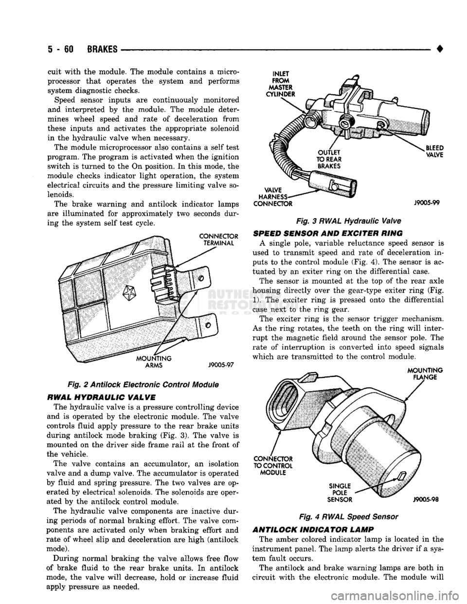
Fig.
2
Antilock
Electronic Control
Module
RWAL
HYDRAULIC
VALVE
The hydraulic valve is a pressure controlling device
and is operated by the electronic module. The valve
controls fluid apply pressure to the rear brake units
during antilock mode braking (Fig. 3). The valve is
mounted on the driver side frame rail at the front of
the vehicle.
The valve contains an accumulator, an isolation
valve and a dump valve. The accumulator is operated
by fluid and spring pressure. The two valves are op erated by electrical solenoids. The solenoids are oper
ated by the antilock control module.
The hydraulic valve components are inactive dur
ing periods of normal braking effort. The valve com
ponents are activated only when braking effort and rate of wheel slip and deceleration are high (antilock
mode).
During normal braking the valve allows free flow
of brake fluid to the rear brake units. In antilock
mode, the valve will decrease, hold or increase fluid
apply pressure as needed. •
CONNECTOR
J9005-99
Fig. 3 RWAL Hydraulic Valve
SPEED
SENSOR
AND EXCITER RING
A single pole, variable reluctance speed sensor is
used to transmit speed and rate of deceleration in
puts to the control module (Fig. 4). The sensor is ac
tuated by an exiter ring on the differential case.
The sensor is mounted at the top of the rear axle
housing directly over the gear-type exiter ring (Fig.
1).
The exciter ring is pressed onto the differential
case next to the ring gear.
The exciter ring is the sensor trigger mechanism.
As the ring rotates, the teeth on the ring will inter
rupt the magnetic field around the sensor pole. The rate of interruption is converted into speed signals
which are transmitted to the control module.
Fig.
4
RWAL Speed Sensor
ANTILOCK INDICATOR LAMP The amber colored indicator lamp is located in the
instrument panel. The lamp alerts the driver if a sys
tem fault occurs.
The antilock and brake warning lamps are both in
circuit with the electronic module. The module will
cuit with the module. The module contains a micro
processor that operates the system and performs system diagnostic checks. Speed sensor inputs are continuously monitored
and interpreted by the module. The module deter
mines wheel speed and rate of deceleration from
these inputs and activates the appropriate solenoid in the hydraulic valve when necessary.
The module microprocessor also contains a self test
program. The program is activated when the ignition switch is turned to the On position. In this mode, the
module checks indicator light operation, the system
electrical circuits and the pressure limiting valve so
lenoids.
The brake warning and antilock indicator lamps
are illuminated for approximately two seconds dur
ing the system self test cycle.
Page 248 of 1502
•
BRAKES
5 - 61 cause the two lamps to illuminate or flash to alert
the driver that system operation is either normal or
that a fault has occurred.
SYSTEM
OPERATION
During light brake applications, rear wheel decel
eration and/or slip is not sufficient to activate the an
tilock system. Brake fluid apply pressure at the rear
wheels is normal. However, when braking effort, de gree of wheel slip and rate of deceleration approach
programmed limits, sensor inputs will cause the module to activate the system.
Normal
Braking
Mode
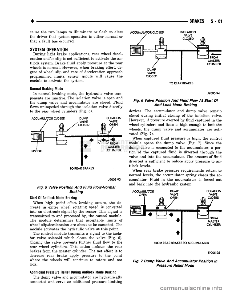
In normal braking mode, the hydraulic valve com
ponents are inactive. The isolation valve is open and
the dump valve and accumulator are closed. Fluid
flows unimpeded through the isolation valve directly
to the rear wheel cylinders (Fig. 5).
ACCUMULATOR
CLOSED
ACCUMULATOR
CLOSED
0 m
m
0 UUb Ft
L DUMP
VALVE
CLOSED
SPRING
ISOLATION
VALVE
OPEN
FROM
MASTER
CYLINDER TO
REAR
BRAKES
J9005-93
Fig.
5
Valve
Position And Fluid Flow-Normal
Braking
Start
Of
Antilock
Mode
Braking
When high pedal effort braking occurs, the de
crease in exiter wheel rotating speed is converted
into an electronic signal by the sensor. This signal is
transmitted to and processed by, the control module.
The module determines that acceptable limits of wheel slip/deceleration are about to be exceeded. The
module activates the hydraulic valve at this point.
The control module transmits a signal to the isola
tor valve solenoid which closes the valve (Fig. 6). Closing the valve prevents further fluid flow to the
rear wheel cylinders. This action isolates the rear
brakes from the master cylinder. The net effect is to decrease rear brake apply pressure to the point
where the wheels will continue to rotate and not lock.
Additional
Pressure
Relief
During
Antilock
Mode
Braking
The dump valve and accumulator are hydraulically
connected and serve as additional pressure limiting
ISOLATION
VALVE
CLOSED
FROM
MASTER
CYLINDER
DUMP
VALVE
CLOSED
TO
REAR
BRAKES
J9005-94
Fig.
6
Valve
Position And Fluid Flow At
Start
Of
Anti-Lock
Mode
Braking
devices. The accumulator and dump valve remain
closed during initial closing of the isolation valve.
However, if pressure exerted by fluid captured in the
wheel cylinders and lines is high enough to lock the
wheels, the dump valve and accumulator are acti vated (Fig. 7).
When captured fluid pressure is high, the control
module opens the dump valve (Fig. 7). Since the
dump valve is connected to the accumulator, a por
tion of the captured fluid is diverted through the
valve and into the accumulator. The amount of fluid diverted is sufficient to reduce apply pressure to an
tilock levels.
When rear brake pressure requirements return to
normal levels, the accumulator spring closes the ac cumulator. Fluid in the accumulator is forced out
and back into the hydraulic system.
ACCUMULATOR OPEN DUMP
VALVE
OPEN ISOLATION
VALVE
CLOSED
FROM
MASTER
CYLINDER
FROM
REAR
BRAKES
TO ACCUMULATOR
J9005-95
Fig.
7 Dump
Valve
And
Accumulator
Position In
Pressure
Relief
Mode
Page 249 of 1502
i - 62
BRAKES
•
Isolation/Dump
Valve Cycle Times
Activation (opening/closing) of the isolation and
dump valves is continuous during antilock operation.
The valves cycle rapidly in response to speed sensor inputs and control module signal commands. Cycle
times are measured in milliseconds.
As the demand for antilock mode brake operation
is decreased, the module deactivates the hydraulic
valve components to restore normal brake operation.
ANTILOCK
SERVICE
DIAGNOSIS
GENERAL INFORMATION An antilock system malfunction will be indicated
by illumination of the amber antilock warning lamp.
The red brake warning lamp may also illuminate.
If a problem occurs, system diagnosis should begin
with a fluid level check followed by a visual exami
nation of the system electrical and hydraulic connec
tions.
If obvious defects (low fluid, leaks, loose connections, etc.) are not evident, road test the vehi
cle.
A road test should help determine if a malfunc
tion is actually related to an antilock component.
During the road test, note if other conditions are
evident such as a low pedal, pull, grab, or similar condition. Remember that brake malfunctions such as low fluid, system leaks, parking brakes partially
applied, will also affect the antilock system. The idea
is to determine if a malfunction is actually related to
an anti-lock component.
If a road test does reveal a problem, repeat the
road test with the owner driving. Make sure the owner is not riding the brake pedal, or has forgotten
to release the parking brakes. Either situation will
generate a fault and cause the antilock light to illu
minate.
SYSTEM FAULT
CODES
The antilock control module generates flash codes
to help identify the cause of an antilock system fault. Two different control modules are used with the
1992/1993 RWAL system. A type I module is used in
some early production models. All remaining produc
tion models are equipped with a type II module. The type I and II modules are identified by the way
fault codes 9 and 11 are processed. If the vehicle has a type I module, codes 9 and 11 are not erased when
the ignition switch is turned to Off position. If the vehicle has a type II module, codes 9 and 11 are
erased when the switch is turned to Off.
FAULT CODES WITH TYPE I CONTROL
MODULE
The microprocessor in the electronic control module
has a memory and a self test feature. The self test
feature is activated whenever the ignition switch is
turned to Accessory or Run position. If a system fault is detected, the control module il
luminates the antilock light and stores the fault code
in memory. Fault codes are retained in memory even after turning the ignition switch to Off position.
FAULT CODES WITH TYPE II CONTROL
MODULE The microprocessor in the electronic control module
has a memory and a self test feature. The self test
feature is activated whenever the ignition switch is
turned to Accessory or Run position.
If a system fault is detected, the control module
will illuminate the antilock indicator lamp and store
fault codes 1 through 8, 10 and 12 through 15 in the
microprocessor memory. When one of these fault
codes is generated, the control module will retain the code after the ignition switch is turned to the Off po
sition.
When fault code 9 is generated, the code only re
mains in microprocessor memory while the ignition switch is in Run position. Turning the ignition
switch to Off position erases fault code 9. However, if
the problem still exists when the switch is turned
back to Run position, code 9 will reappear in memory after 20 seconds and the antilock light will illumi
nate once again.
When fault code 11 is generated, the antilock light
will illuminate when vehicle speed exceeds approxi mately 60.35 km/h (37.5 mph). Code 11 only remains in memory while the ignition switch is in the Run
position and the fault is present.
When the cause of a fault code 11 is corrected, the
antilock light goes off. Code 11 is erased when the ig
nition switch is turned to Off position. However, if
the problem cause still exists when the ignition switch is turned to Run position, code 11 will reap
pear when vehicle speed exceeds approximately 60.35 km/h (37.5 mph).
FAULT
CODE
CAPACITY
The microprocessor memory will store and display
only one fault code at a time. The stored code can be
displayed by grounding the RWAL diagnostic connec
tor.
FAULT
CODE
IDENTIFICATION
To determine what the fault code is, momentarily
ground the RWAL diagnostic connector and count
the number of times the amber antilock lamp flashes. Fault codes and typical malfunctions are outlined in Figure 8. Note that when a fault code is gen
erated, the red brake warning lamp will also
illuminate. The initial flash will be a long flash followed by a
number of short flashes. The long flash indicates the
beginning of the fault number sequence and the short flashes are a continuation of that sequence.
Page 322 of 1502
•
ELECTRICAL
ELECTRICAL
8A - 1
Group
AUDIO
SYSTEMS
8F
BATTERY/STARTER/GENERATOR
SERVICE
.. 8B
BATTERY/STARTING/CHARGING
SYSTEMS
DIAGNOSTICS
8A
HORNS
8G
IGNITION
SYSTEMS
8D
INSTRUMENT PANEL AND
GAUGES
8E
LAMPS
8L
POWER
LOCKS
8P
INDEX
Group
POWER
MIRRORS
8T
POWER
WINDOWS 8S
REAR
WINDOW DEFOGGER 8N
TURN
SIGNALS
AND HAZARD WARNING
FLASHERS
8J
VEHICLE
SPEED
CONTROL SYSTEM 8H WARNING BUZZER SYSTEM 8U
WINDSHIELD WIPERS AND
WASHERS
8K
WIRING DIAGRAMS 8W
BATTERY/STARTING/CHARGING SYSTEMS DIAGNOSTICS
CONTENTS
page
page
BATTERY TEST
PROCEDURES
2 GENERATOR TEST
PROCEDURES
ON VEHICLE . 13
ENGINE
STARTER MOTOR TEST
PROCEDURES
..9 SPECIFICATIONS 18
GENERAL
INFORMATION 1
GENERAL INFORMATION
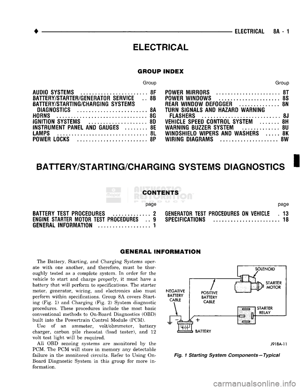
The Battery, Starting, and Charging Systems oper
ate with one another, and therefore, must be thor
oughly tested as a complete system. In order for the
vehicle to start and charge properly, it must have a
battery that will perform to specifications. The starter
motor, generator, wiring, and electronics also must
perform within specifications. Group 8A covers Start ing (Fig. 1) and Charging (Fig. 2) System diagnostic
procedures. These procedures include the most basic
conventional methods to On-Board Diagnostics (OBD)
built into the Powertrain Control Module (PCM).
Use of an ammeter, volt/ohmmeter, battery
charger, carbon pile rheostat (load tester), and 12
volt test light will be required.
All OBD sensing systems are monitored by the
PCM. The PCM will store in memory any detectable
failure in the monitored circuits. Refer to Using On-
Board Diagnostic System in this group for more in formation.
NEGATIVE
BATTERY
CABLE
A
7
POSITIVE
BATTERY
CABLE
BATTERY
J918A-11
Fig.
1 Starting
System
Components—Typical
Page 358 of 1502
•
IGNITION
SYSTEMS
80 - 7
DIAGNOSTICS/SERW1CE
PROCEDURES
INDEX
page
Automatic Shut Down (ASD) Relay
7
Camshaft Position
Sensor
Test
...............
7
Crankshaft Position
Sensor
Test
8
Distributor
Cap
8
Distributor
Rotor
8
Engine
Coolant Temperature
Sensor
Test
10
General
Information
7
Ignition
Coil
8
Ignition
Secondary
Circuit
Diagnosis
10
GENERAL
INFORMATION
This section
of the
group, Diagnostics/Service Pro
cedures, will discuss basic ignition system diagnos
tics
and
service adjustments. For system operation
and
component identification,
refer
to the
Component Identification/System Opera
tion section
of
this group. For removal
or
installation
of
ignition system com
ponents, refer
to the
Component Removal/Installa
tion section
of
this group. For other useful information, refer
to
On-Board
Di
agnostics
in the
General Diagnosis sections
of
Group
14,
Fuel System
in
this manual. For operation
of the DRB II
Diagnostic Scan Tool,
refer
to the
appropriate Powertrain Diagnostic Proce
dures service manual.
AUTOMATIC SHUT DOWN
(ASD)
RELAY
Refer
to
Relays—Operation/Testing
in the
Group
14,
Fuel System section
of
this service manual.
CAMSHAFT POSITION SENSOR TEST
The camshaft position sensor
is
located
in the
dis
tributor
on all
engines. To perform
a
complete test
of
this sensor
and its
circuitry, refer
to the DRB II
diagnostic scan tool.
Also refer
to the
appropriate Powertrain Diagnostics
Procedures manual.
To
test
the
sensor only, refer
to
the following: For this test,
an
analog (non-digital) voltmeter
is needed.
Do not
remove
the
distributor connector from
the
distributor. Using small paper clips, insert
them into
the
backside
of the
distributor wire har ness connector
to
make contact with
the
terminals.
Be sure that
the
connector
is not
damaged when
in
serting
the
paper clips. Attach voltmeter leads
to
these paper clips. (1) Connect
the
positive (
+
)
voltmeter lead into
the sensor output wire. This
is at
done
the
distribu tor wire harness connector.
For
wire identification,
refer
to
Group
8W,
Wiring Diagrams.
page
Ignition
Timing
12
Intake Manifold Charge
Air
Temperature
Sensor
Test
12
Manifold Absolute Pressure (MAP)
Sensor
Test
. 12
Oxygen
Sensor
Tests
17
Powertrain Control Module (PCM)
............
14
Spark
Plug Secondary Cables
16
Spark
Plugs
............................
14
Throttle
Position
Sensor
Test
17
(2) Connect
the
negative
(-)
voltmeter lead into
the
ground wire.
For
wire identification, refer
to
Group
8W, Wiring Diagrams.
(3)
Set the
voltmeter
to the 15
Volt
DC
scale. (4) Remove distributor
cap
from distributor
(two
screws). Rotate (crank)
the
engine until
the
distribu
tor rotor
is
pointed towards
the
rear
of
vehicle.
The
movable pulse ring should
now be
within
the
sensor
pickup.
(5) Turn ignition
key to ON
position. Voltmeter
should read approximately
5.0
volts.
(6)
If
voltage
is not
present, check
the
voltmeter
leads
for a
good connection.
(7)
If
voltage
is
still
not
present, check
for
voltage
at
the
supply wire.
For
wire identification, refer
to
Group
8W,
Wiring Diagrams.
(8)
If
voltage
is not
present
at
supply wire, check
for voltage
at
pin-7
of
powertrain control module (PCM) 60-way connector. Leave
the PCM
connector
connected
for
this test. (9)
If
voltage
is
still
not
present, perform vehicle
test using
the DRB II
diagnostic scan tool. (10)
If
voltage
is
present
at
pin-7,
but not at the
supply wire: (a) Check continuity between
the
supply wire.
This
is
checked between
the
distributor connector and pin-7
at the PCM. If
continuity
is not
present,
repair
the
harness
as
necessary. (b) Check
for
continuity between
the
camshaft
position sensor output wire
and
pin-44
at the PCM.
If continuity
is not
present, repair
the
harness
as
necessary. (c) Check
for
continuity between
the
ground cir
cuit wire
at the
distributor connector
and
ground.
If continuity
is not
present, repair
the
harness
as
necessary. (11) While observing
the
voltmeter, crank
the en
gine with ignition switch.
The
voltmeter needle should fluctuate between
0 and 5
volts while
the en
gine
is
cranking. This verifies that
the
camshaft
po
sition sensor
in the
distributor
is
operating properly
and
a
sync pulse signal
is
being generated.
Page 376 of 1502
IGNITION
SYSTEMS
80 - 25
IGNITION
SWITCH
INDEX
General
Information
page
. . 25
GENERAL
INFORMATION
The ignition switch is located in the steering col
umn. The Key-In-Switch and Halo Light are integral
with the ignition switch. Refer to Group 8M for Key- In-Switch and Halo Light diagnosis.
IGNITION
SWITCH
AND
KEY
CYLINDER
SERVICE
REMOVAL
(1) Disconnect negative battery cable.
(2) Tilt column: Remove tilt lever (counterclock
wise).
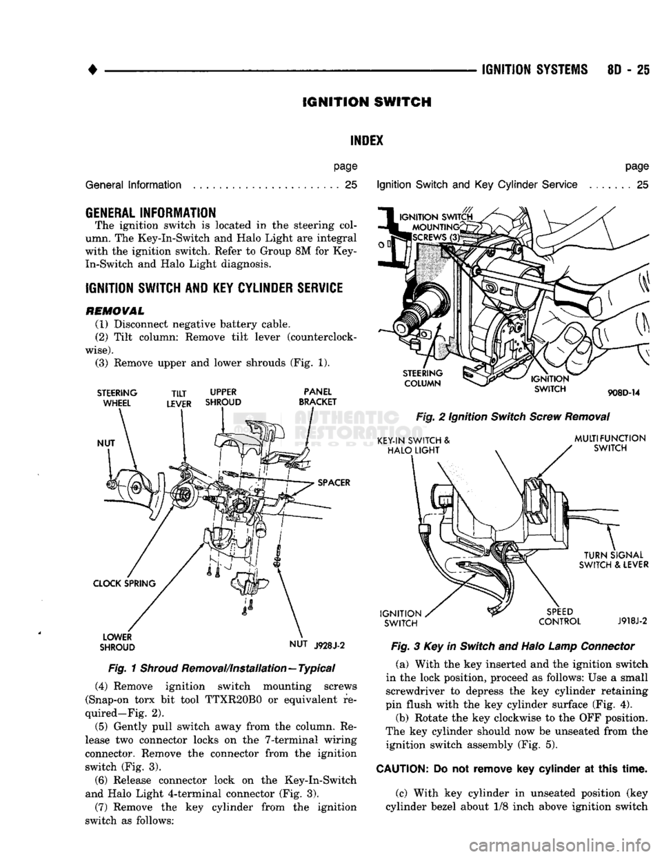
(3) Remove upper and lower shrouds (Fig. 1).
STEERING
WHEEL
NUT
TILT
UPPER
LEVER SHROUD PANEL
BRACKET
SPACER
CLOCK SPRING LOWER
SHROUD NUT
J928J-2
Fig.
1
Shroud
Removal/Installation—Typical (4) Remove ignition switch mounting screws
(Snap-on torx bit tool TTXR20B0 or equivalent re
quired—Fig. 2).
(5) Gently pull switch away from the column. Re
lease two connector locks on the 7-terminal wiring
connector. Remove the connector from the ignition switch (Fig. 3).
(6) Release connector lock on the Key-In-Switch
and Halo Light 4-terminal connector (Fig. 3).
(7) Remove the key cylinder from the ignition
switch as follows:
Ignition
Switch
and Key
Cylinder
Service
page
. . 25
STEERING
COLUMN
IGNITION
SWITCH
908D-14
Fig.
2 Ignition
Switch
Screw
Removal
KEY-IN SWITCH &
HALO
LIGHT
MULTIFUNCTION
SWITCH
IGNITION
SWITCH
TURN
SIGNAL
SWITCH & LEVER
SPEED
CONTROL
J918J-2
Fig.
3 Key in
Switch
and Halo
Lamp
Connector
(a) With the key inserted and the ignition switch
in the lock position, proceed as follows: Use a small screwdriver to depress the key cylinder retaining
pin flush with the key cylinder surface (Fig. 4).
(b) Rotate the key clockwise to the OFF position.
The key cylinder should now be unseated from the ignition switch assembly (Fig. 5).
CAUTION:
Do not
remove
key
cylinder
at
this
time.
(c) With key cylinder in unseated position (key
cylinder bezel about 1/8 inch above ignition switch