1993 DODGE TRUCK turn signal
[x] Cancel search: turn signalPage 909 of 1502
14
- 90
FUEL SYSTEM
Fig.
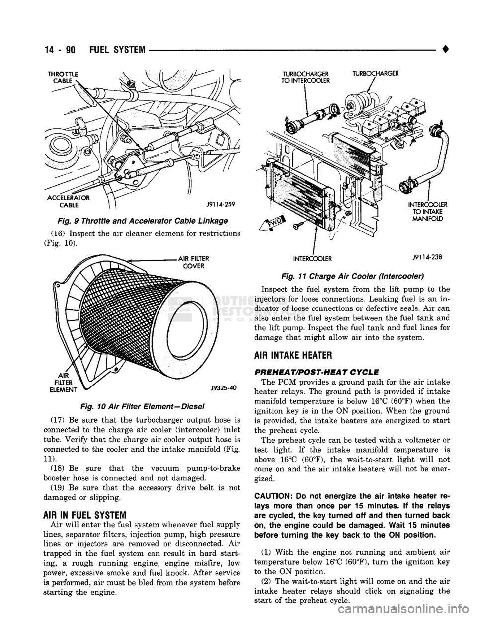
10 Air
Filter
Element—Diesel (17) Be sure that the turbocharger output hose is
connected to the charge air cooler (intercooler) inlet
tube.
Verify that the charge air cooler output hose is
connected to the cooler and the intake manifold (Fig.
11).
(18) Be sure that the vacuum pump-to-brake
booster hose is connected and not damaged. (19) Be sure that the accessory drive belt is not
damaged or slipping.
AIR
IN
FUEL SYSTEM
Air will enter the fuel system whenever fuel supply
lines,
separator filters, injection pump, high pressure
lines or injectors are removed or disconnected. Air
trapped in the fuel system can result in hard start
ing, a rough running engine, engine misfire, low
power, excessive smoke and fuel knock. After service is performed, air must be bled from the system before
starting the engine. •
Fig.
11
Charge
Air
Cooler
(Intercooler) Inspect the fuel system from the lift pump to the
injectors for loose connections. Leaking fuel is an in
dicator of loose connections or defective seals. Air can also enter the fuel system between the fuel tank and
the lift pump. Inspect the fuel tank and fuel lines for damage that might allow air into the system.
AIR INTAKE HEATER PREHEAT/POST-HEAT CYCLE
The PCM provides a ground path for the air intake
heater relays. The ground path is provided if intake
manifold temperature is below 16°C (60°F) when the
ignition key is in the ON position. When the ground is provided, the intake heaters are energized to start
the preheat cycle.
The preheat cycle can be tested with a voltmeter or
test light. If the intake manifold temperature is above 16°C (60°F), the wait-to-start light will not
come on and the air intake heaters will not be ener gized.
CAUTION:
Do not
energize
the air
intake
heater
re
lays
more than once
per 15
minutes.
If the
relays
are cycled,
the key
turned
off and
then
turned
back
on,
the
engine could
be
damaged. Wait
15
minutes before turning
the key
back
to the ON
position.
(1) With the engine not running and ambient air
temperature below 16°C (60°F), turn the ignition key
to the ON position.
(2) The wait-to-start light will come on and the air
intake heater relays should click on signaling the
start of the preheat cycle.
Page 918 of 1502
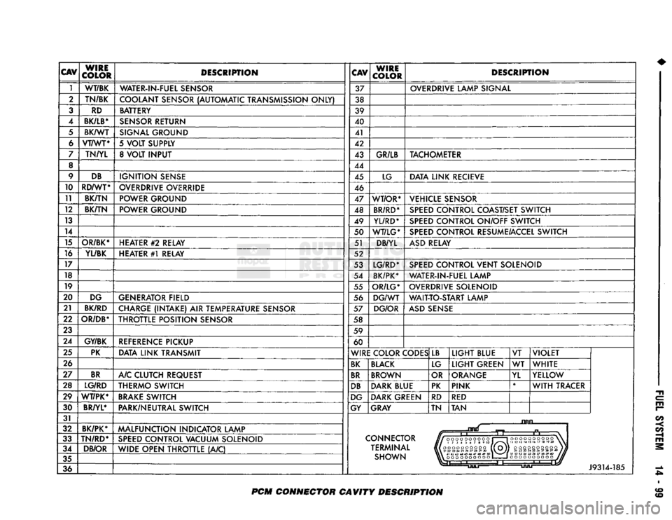
CAV
WIRE
COLOR DESCRIPTION
CAV
WIRE
COLOR DESCRIPTION
1 WT/BK
WATER-IN-FUEL SENSOR 37 OVERDRIVE LAMP SIGNAL
2 TN/BK
COOLANT SENSOR (AUTOMATIC TRANSMISSION ONLY) 38
3 RD BATTERY
39
4
BK/LB*
SENSOR RETURN 40
5 BK/WT
SIGNAL GROUND 41
6 VT/WT*
5 VOLT SUPPLY 42
7 TN/YL 8 VOLT INPUT 43 GR/LB TACHOMETER
8 44
9 DB
IGNITION SENSE 45 LG DATA LINK RECIEVE
10 RD/WT*
OVERDRIVE OVERRIDE 46
11 BK/TN POWER GROUND
47 WT/OR* VEHICLE SENSOR
12 BK/TN
POWER GROUND 48 BR/RD* SPEED CONTROL COAST/SET SWITCH
13 49 YL/RD* SPEED CONTROL ON/OFF SWITCH
14 50 WT/LG* SPEED CONTROL RESUME/ACCEL SWITCH
15 OR/BK* HEATER
#2
RELAY 51 DB/YL ASD RELAY
16 YL/BK HEATER #1 RELAY 52
17 53 LG/RD* SPEED CONTROL VENT SOLENOID
18 54 BK/PK* WATER-IN-FUEL LAMP
19 55 OR/LG* OVERDRIVE SOLENOID
20 DG GENERATOR FIELD 56 DG/WT WAIT-TO-START LAMP
21 BK/RD
CHARGE (INTAKE) AIR TEMPERATURE SENSOR 57 DG/OR ASD SENSE
22
OR/DB*
THROTTLE POSITION SENSOR 58
23 59
24 GY/BK
REFERENCE PICKUP 60
25 PK
DATA LINK TRANSMIT WIRE COLOR CODES LB
LIGHT BLUE VT VIOLET
26 BK BLACK LG LIGHT GREEN WT
WHITE
27 BR
A/C CLUTCH REQUEST BR BROWN OR ORANGE
YL YELLOW
28 LG/RD THERMO SWITCH DB DARK BLUE PK PINK *
WITH TRACER
29 WT/PK* BRAKE SWITCH DG DARK GREEN
RD RED
30 BR/YL*
PARK/NEUTRAL SWITCH GY GRAY TN TAN
31 ruin
32 BK/PK*
MALFUNCTION INDICATOR LAMP
n
33 TN/RD*
SPEED CONTROL VACUUM SOLENOID CONNECTOR
J//000OOOOOOO
1 1
HI
173456789
10 J/^"*\
Hi
oooooooooo (1 Oj]
VlX
21
22
23
24
25
26
27
28
29
30
\V~V//
oooooooooo
\
II
12 13
14 15
16 17 18
19 20
\
34 DB/OR
WIDE OPEN THROTTLE (A/C) TERMINAL
J//000OOOOOOO
1 1
HI
173456789
10 J/^"*\
Hi
oooooooooo (1 Oj]
VlX
21
22
23
24
25
26
27
28
29
30
\V~V//
oooooooooo)}
31
32 33 34 35 36 37 38 39 40
1JU
35 SHOWN \\\
41 42 43 44 45 46 47 48 49
SO
1
^m^^
|
oooooooooo
1
1
oooooooooo
J//
36
Li
J9314-185
PCM
CONNECTOR CAVITY DESCRIPTION
Page 998 of 1502
•
STEERING
19 • 37 (4) From the end of travel, rotate the rotor 2 1/2
full turns in the COUNTER CLOCKWISE direction.
The horn wire should end up at the top and the squib
wire at the bottom (Fig. 4).
(5) Install the steering wheel, refer to Steering
Wheel Installation.
COLUMN—
REMOVAL/INSTALLATION
CAUTION:
Bumping,
jolting
and
hammering
on the
steering
column
shaft
and
gear
shift
tube
must
be
avoided
during
all
service
procedures.
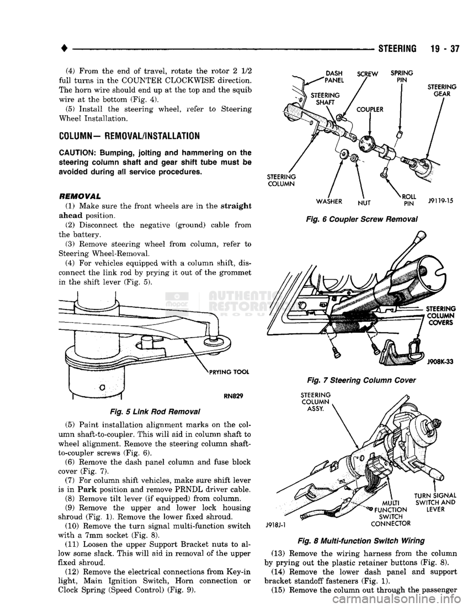
REMOVAL (1) Make sure the front wheels are in the straight
ahead position.
(2) Disconnect the negative (ground) cable from
the battery.
(3) Remove steering wheel from column, refer to
Steering Wheel-Removal.
(4) For vehicles equipped with a column shift, dis
connect the link rod by prying it out of the grommet in the shift lever (Fig. 5).
DASH
"PANEL SCREW
SPRING
PIN
PRYING
TOOL
RN829
Fig.
5
Link
Rod
Removal
(5) Paint installation alignment marks on the col
umn shaft-to-coupler. This will aid in column shaft to
wheel alignment. Remove the steering column shaft-
to-coupler screws (Fig. 6).
(6) Remove the dash panel column and fuse block
cover (Fig. 7).
(7) For column shift vehicles, make sure shift lever
is in Park position and remove PRNDL driver cable.
(8) Remove tilt lever (if equipped) from column.
(9) Remove the upper and lower lock housing
shroud (Fig. 1). Remove the lower fixed shroud.
(10) Remove the turn signal multi-function switch
with a 7mm socket (Fig. 8). (11) Loosen the upper Support Bracket nuts to al
low some slack. This will aid in removal of the upper
fixed shroud.
(12) Remove the electrical connections from Key-in
light, Main Ignition Switch, Horn connection or
Clock
Spring (Speed
Control)
(Fig. 9).
STEERING
GEAR
STEERING COLUMN
WASHER NUT
RJ?N"
J9119-15
Fig.
6
Coupler
Screw
Removal
STEERING COLUMN COVERS
J908K-33
Fig.
7 Steering
Column
Cover
STEERING COLUMN
ASSY.
J918J-1
MULTI
^FUNCTION
SWITCH
CONNECTOR
TURN
SIGNAL
SWITCH
AND
LEVER
Fig.
8 Multi-function
Switch
Wiring (13) Remove the wiring harness from the column
by prying out the plastic retainer buttons (Fig. 8).
(14) Remove the lower dash panel and support
bracket standoff fasteners (Fig. 1). (15) Remove the column out through the passenger
Page 1488 of 1502
•
EMISSION
CONTROL
SYSTEMS
25 - 11 • The electrical solenoid portion of the EET is not
energized.
• The engine back pressure entering the EGR valve
inlet is strong enough to close the transducer bleed
valve.
If back pressure is not strong enough to close the
transducer bleed valve, the transducer will bleed off the vacuum preventing EGR operation.
When the electrical solenoid portion of the EET is
de-energized by the powertrain control module (PCM), vacuum flows to the transducer. The trans
ducer is connected to the engine exhaust system by a small hose that connects to the base of the EGR
valve.
The vacuum section of the transducer is controlled
by exhaust system back pressure. When back pres sure is high enough it will close a bleed valve in the
transducer allowing vacuum to actuate the EGR
valve. If back pressure does not close the bleed valve,
vacuum will be bled off.
For more information, refer to Group 14, Fuel Sys
tems.
Refer to the Component Removal/Installation sec
tion of this group for EGR valve replacement proce
dures.
EGR SYSTEM ON-BOARD DIAGNOSTICS
(CALIFORNIA VEHICLES
ONLY)
The powertrain control module (PCM) performs an
On-Board Diagnostic (OBD) check of the EGR system
on all California vehicles. The diagnostic system uses
the electric EGR transducer (EET) for the system
tests.
The OBD check activates only during selected en
gine/driving conditions. When the conditions are met,
the PCM energizes the EET solenoid to disable the EGR. The PCM checks for a change in the oxygen sensor signal. If the air-fuel mixture goes lean, the
PCM will attempt to enrichen the mixture. The PCM
registers a diagnostic trouble code (DTC) if the EGR system has failed or degraded. After registering a
DTC,
the PCM turns the malfunction indicator
lamp (MIL) on. (The malfunction indicator lamp was formerly referred to as the check engine lamp). The
malfunction indicator lamp indicates the need for im
mediate service.
If a malfunction is indicated by the malfunction in
dicator lamp and a DTC for the EGR system was set,
check for proper operation of EGR system. Use the
following: System Test, EGR Gas Flow Test and EGR
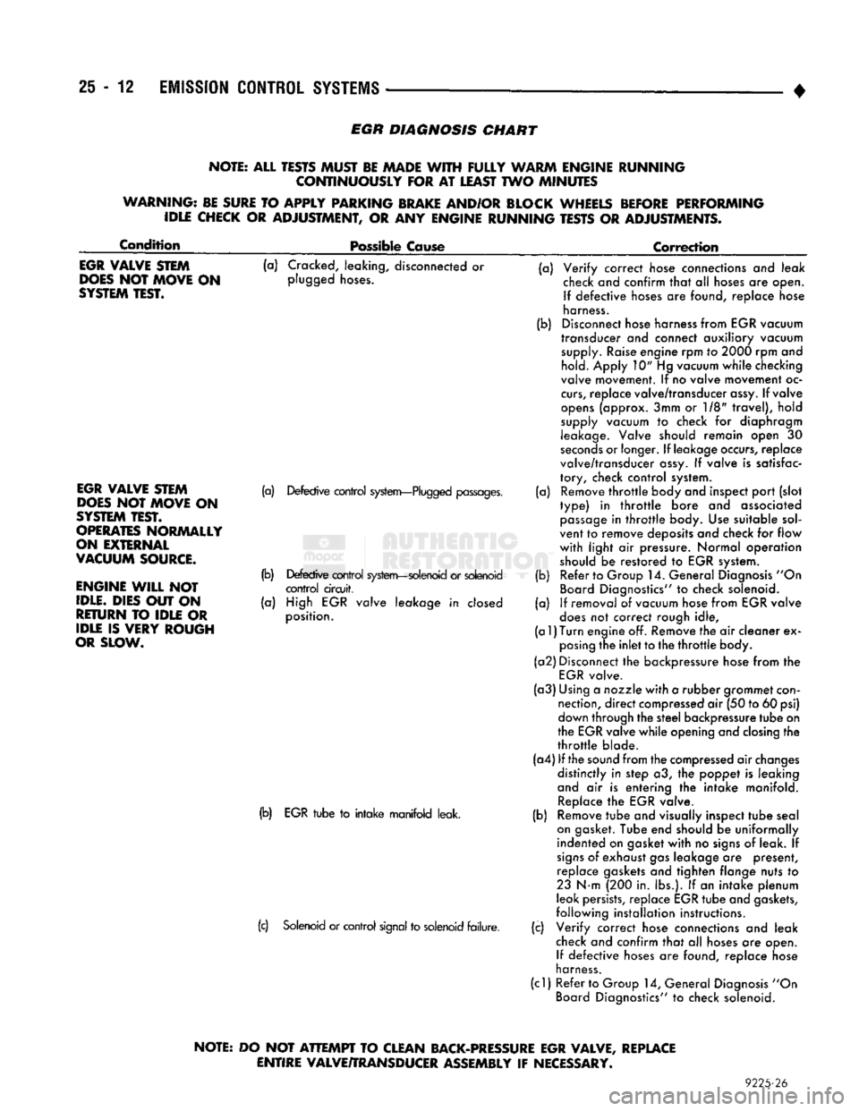
Diagnosis Chart.
If the EGR system tests properly, check the system
using the DRB II scan tool. For use of the DRB II,
refer to the appropriate Powertrain Diagnostics Pro cedure service manual. EGR SYSTEM SERVICE
A malfunctioning EGR system can cause engine
spark knock, sags or hesitation, rough idle, engine
stalling and poor driveability. To be sure of proper
operation of the EGR system, inspect all passages for
blockage. Check moving parts for binding. Inspect
the complete system for leaks. Replace system com ponents or hoses that are leaking.
Inspect all hose connections between throttle body,
intake manifold, EGR valve and EGR purge solenoid.
Replace any vacuum harness components that are
leaking or damaged. Refer to EGR Control System Test and EGR Gas
Flow Test to check EGR System operation.
EGR GAS FLOW TEST (1) Disconnect hose from EGR valve and connect a
hand vacuum pump to EGR valve nipple. Apply a
minimum of 12 inches vacuum the valve.
(2) The engine should now idle roughly or stall. If
this occurs, the valve is performing correctly. Proceed
to Electric EGR Transducer Test.
(3) If the engine idle speed did not change, remove
the EGR valve and inspect the valve and the exhaust passage in the manifold for blockage. Repair as nec
essary. If blockage is not present, replace the EGR
valve.
ELECTRIC EGR TRANSDUCER (EET)
TESTING ELECTRIC SOLENOID PORTION OF TRANSDUCER
(1) Bring the engine to normal operating tempera
ture.
Operate at idle speed. Test the EET as follows: (2) Check vacuum at EET vacuum source. Discon
nect the hose and attach a vacuum gauge to it.
(3) Vacuum should be a minimum of 15 inches:
• If vacuum is low, check the line for kinks, twists
or a loose connection at vacuum connector or intake
manifold.
• If vacuum is correct, remove gauge. Connect the
vacuum line and proceed to next step. (4) Check EET operation using the appropriate
Powertrain Diagnostic Procedures service manual.
Refer to this manual for use of the DRB II scan tool and repair EET as necessary.
TESTING VACUUM PORTION
OF
TRANSDUCER
(1) Disconnect the EET vacuum lines, back pres
sure line and electrical connector. Remove trans
ducer.
(2) Plug the EET EGR valve port.
(3) Apply 1-2 pounds air pressure to exhaust back
pressure port. Air pressure can be supplied with a
hand operated air pump or compressed air (regulated
to correct psi).
(4) Apply a minimum of 12 inches of vacuum to
vacuum supply port.
Replace the EET if it will not hold vacuum.
Page 1489 of 1502
25
- 12
EMISSION
CONTROL
SYSTEMS
EGR
DIAGNOSIS
CHART
NOTE: ALL TESTS MUST BE MADE
WITH
FULLY
WARM ENGINE RUNNING CONTINUOUSLY FOR
AT
LEAST TWO MINUTES
WARNING: BE SURE
TO
APPLY PARKING BRAKE AND/OR BLOCK WHEELS BEFORE PERFORMING IDLE CHECK
OR
ADJUSTMENT,
OR ANY
ENGINE RUNNING TESTS
OR
ADJUSTMENTS.
Condition
Possible Cause
Correction
EGR
VALVE STEM
DOES
NOT MOVE
ON
SYSTEM
TEST.
(a) Cracked, leaking, disconnected or
plugged hoses.
EGR
VALVE STEM
DOES
NOT MOVE
ON
SYSTEM
TEST.
OPERATES
NORMALLY
ON EXTERNAL
VACUUM
SOURCE.
ENGINE
WILL
NOT
IDLE.
DIES OUT
ON
RETURN
TO
IDLE
OR
IDLE
IS
VERY ROUGH
OR SLOW.
(a) Defective control system—Plugged passages.
(b) Defective control system—solenoid or solenoid control circuit,
(a) High EGR valve leakage in closed
position.
(b) EGR tube to intake manifold leak.
(c) Solenoid or control signal to solenoid failure. (a)
(b)
(a)
(b)
(a) Verify correct hose connections and leak
check and confirm that alt hoses are open.
If defective hoses are found, replace hose
harness.
Disconnect hose harness from EGR vacuum
transducer and connect auxiliary vacuum supply. Raise engine rpm to 2000 rpm and hold. Apply 10" Hg vacuum while checking
valve movement. If no valve movement oc
curs,
replace valve/transducer assy. If valve
opens (approx. 3mm or 1/8" travel), hold
supply vacuum to check for diaphragm
leakage. Valve should remain open 30
seconds or longer. If leakage occurs, replace
valve/transducer assy. If valve is satisfac
tory, check control system. Remove throttle body and inspect port (slot
type) in throttle bore and associated passage in throttle body. Use suitable sol
vent to remove deposits and check for flow
with light air pressure. Normal operation
should be restored to EGR system. Refer to Group 14. General Diagnosis "On
Board Diagnostics" to check solenoid.
If removal of vacuum hose from EGR valve
does not correct rough idle,
(a
1)
Turn
engine off. Remove the air cleaner ex posing the inlet to the throttle body.
(a2) Disconnect the backpressure hose from the EGR valve.
(a3) Using a nozzle with a rubber grommet con nection, direct compressed air (50 to 60 psi)
down through the steel backpressure tube on
the EGR valve while opening and closing the
throttle blade.
(a4) If the sound from the compressed air changes distinctly in step a3, the poppet is leaking
and air is entering the intake manifold. Replace the EGR valve.
Remove tube and visually inspect tube seal
on gasket. Tube end should be uniformally
indented on gasket with no signs of leak. If
signs of exhaust gas leakage are present, replace gaskets and tighten flange nuts to
23 N-m (200 in. lbs.). If an intake plenum
leak persists, replace EGR tube and gaskets,
following installation instructions.
Verify correct hose connections and leak
check and confirm that all hoses are open. If defective hoses are found, replace nose
harness.
(cl) Refer to Group 14, General Diagnosis "On Board Diagnostics" to check solenoid. (b)
(c)
NOTE:
DO
NOT
ATTEMPT
TO CLEAN BACK-PRESSURE EGR VALVE, REPLACE
ENTIRE VALVE/TRANSDUCER ASSEMBLY
IF
NECESSARY.
9225-26
Page 1501 of 1502
CLUSTER
AND
GAUGE SERVICE PROCEDURES
. . . 8E-12
CLUSTER
AND
GAUGE TEST PROCEDURES
8E-5
GENERAL INFORMATION
8E-1
MESSAGE
CENTER-DIESEL ENGINE
8E-4
MESSAGE
CENTER-GAS ENGINE
8E-3
SWITCH
AND
PANEL COMPONENT SERVICE
8E-16
INTRODUCTION
lntro.-1
DESIGNATIONS, LABELS/PLATES/DECALS, CODES AND DIMENSIONS/WEIGHTS
Intro.-1
MEASUREMENT
AND
TORQUE SPECIFICATIONS
lntro.-11
LAMPS
8L-1
BULB APPLICATION
8L-11
EXTERIOR LAMPS
8L-1
EXTERIOR LAMPS SERVICE PROCEDURES
8L-3
INTERIOR LAMPS
8L-10
LUBRICATION
AND
MAINTENANCE
0-1
CHASSIS
AND
BODY
0-28
DRIVETRAIN
0-22
ENGINE MAINTENANCE
0-14
GENERAL INFORMATION
0-1
POWER DOOR LOCKS
8P-1
SERVICE
PROCEDURES
8P-2
TEST PROCEDURES
8P-1
POWER MIRRORS
8T-1
SERVICE
PROCEDURES
8T-2
TEST PROCEDURES
8T-1
POWER WINDOWS
8S-1
SERVICE
PROCEDURES
8S-3
TEST PROCEDURES
8S-1
PROPELLER SHAFTS
16-1
GENERAL INFORMATION
16-1
PROPELLER SHAFT REPLACEMENT
16-8
SERVICE
DIAGNOSIS/PROCEDURES
16-3
TORQUE SPECIFICATIONS
16-15
UNIVERSAL
JOINT
REPLACEMENT
16-10
REAR
SUSPENSION
AND
AXLE
3-1
8
3/8 and 9 1/4
AXLE
3-11
GENERAL INFORMATION
3-1
MODEL
60 and 70
AXLES
3-29
POWER-LOK DIFFERENTIAL
3-55
REAR
SUSPENSION—2WD
and 4WD
VEHICLES
.... 3-3
SERVICE
DIAGNOSIS
3-6
SPECIFICATIONS
3-27
SURE-GRIP
DIFFERENTIAL SERVICE
3-28
TORQUE SPECIFICATIONS
3-59
TRAC-LOK DIFFERENTIAL
3-51
REAR
WINDOW DEFOGGER
8N-1
REPAIR PROCEDURES (GRID LINES, TERMINALS,
AND PIGTAILS)
8N-3
SERVICE
PROCEDURES
8N-4
TEST PROCEDURES
8N-1
STEERING
19-1
GENERAL INFORMATION
19-1
POWER STEERING PUMP
19-11
POWER STEERING SYSTEM DIAGNOSIS
19-2
RECIRCULATING BALL POWER STEERING GEAR
. . 19-20
STEERING COLUMN
19-35
STEERING LINKAGE
19-17
TORQUE SPECIFICATIONS
19-40
TRANSMISSION
AND
TRANSFER CASE
21-1
AUTOMATIC TRANSMISSION DIAGNOSIS
AND
TESTING
21-85
AUTOMATIC TRANSMISSION REMOVAL
AND
INSTALLATION
21-142
AUTOMATIC TRANSMISSION—32RH/36RH/37RH/
42RH/46RH
21-73
G360
MANUAL TRANSMISSION
21-46
G360
TRANSMISSION OVERHAUL
21-53
GENERAL INFORMATION-32RH/36RH/37RH
21-73
GENERAL INFORMATION—42RH/46RH
. . . 21-78
IN-VEHICLE SERVICE—32RH/36RH/37RH/ 42RH/46RH
21-130
NP205
TRANSFER CASE
21-342
NP241
TRANSFER CASE
21-350
NV4500
MANUAL TRANSMISSION
21-1
NV4500
TRANSMISSION OVERHAUL
21-6
OVERDRIVE
UNIT
OVERHAUL—42RH/46RH
21-324
TRANSMISSION OVERHAUL—32RH
21-152
TRANSMISSION OVERHAUL—36RH/37RH
21-192
TRANSMISSION OVERHAUL—42RH
21-233
TRANSMISSION OVERHAUL—46RH
21-278
TRANSMISSION/TRANSFER CASE SPECIFICATIONS
21-364
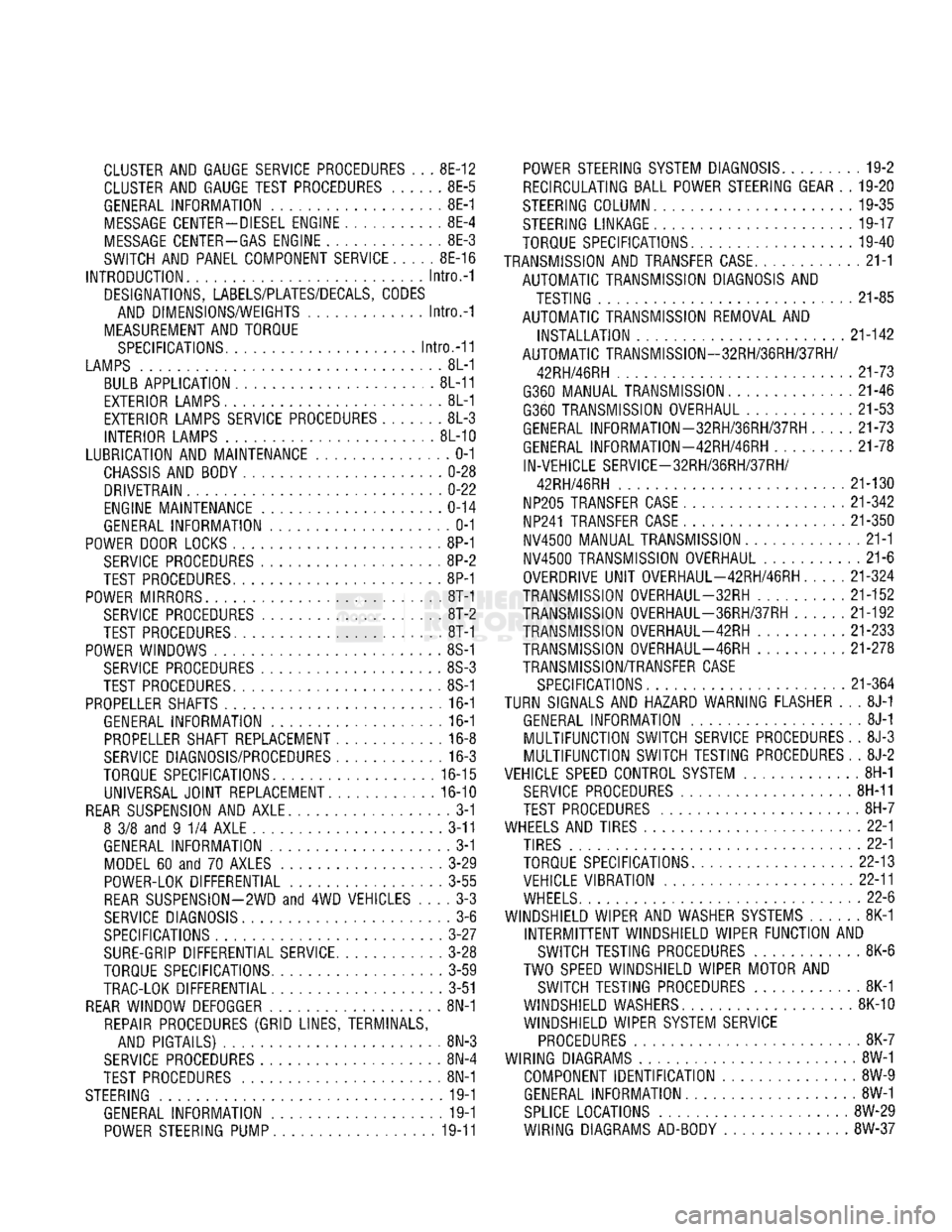
TURN SIGNALS
AND
HAZARD WARNING FLASHER
. . . 8J-1
GENERAL INFORMATION
8J-1
MULTIFUNCTION SWITCH SERVICE PROCEDURES.
. 8J-3
MULTIFUNCTION SWITCH TESTING PROCEDURES.
. 8J-2
VEHICLE
SPEED
CONTROL SYSTEM
8H-1
SERVICE
PROCEDURES
8H-11
TEST PROCEDURES
8H-7
WHEELS
AND
TIRES
22-1
TIRES
22-1
TORQUE SPECIFICATIONS
22-13
VEHICLE VIBRATION
22-11
WHEELS
22-6
WINDSHIELD WIPER
AND
WASHER
SYSTEMS
8K-1
INTERMITTENT WINDSHIELD WIPER FUNCTION
AND
SWITCH TESTING PROCEDURES
8K-6
TWO
SPEED
WINDSHIELD WIPER MOTOR
AND
SWITCH TESTING PROCEDURES
8K-1
WINDSHIELD WASHERS
8K-10
WINDSHIELD WIPER SYSTEM SERVICE
PROCEDURES
8K-7
WIRING DIAGRAMS
8W-1
COMPONENT IDENTIFICATION
8W-9
GENERAL INFORMATION
8W-1
SPLICE
LOCATIONS
8W-29
WIRING DIAGRAMS AD-BODY
8W-37