1993 DODGE TRUCK length
[x] Cancel search: lengthPage 9 of 1502
4 INTRODUCTION
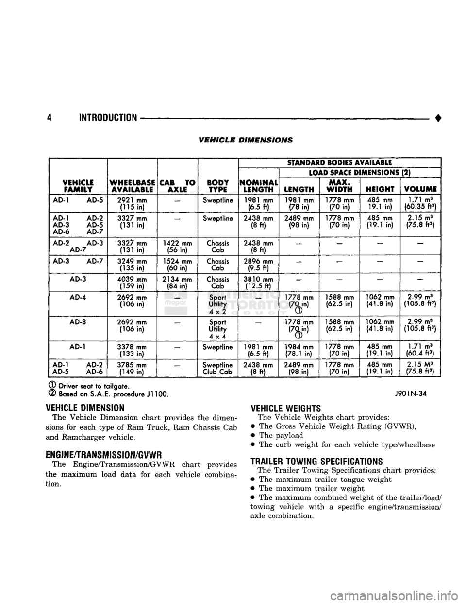
• VEHICLE DIMENSIONS
VEHICLE
FAMILY
WHEELBASE
AVAILABLE
CAB
TO
AXLE BODY
TYPE
SfANDAID
SODIES
AVAILABLE
VEHICLE
FAMILY
WHEELBASE
AVAILABLE
CAB
TO
AXLE BODY
TYPE
NOMINAL
LENGTH
(LOAD
SPACE
D
MENSIONS
(2)
VEHICLE
FAMILY
WHEELBASE
AVAILABLE
CAB
TO
AXLE BODY
TYPE
NOMINAL
LENGTH LENGTH MAX.
WIDTH
HEIGHT
VOLUME
AD-1
AD-5
2921
mm
(115
in) —
Sweptline
1981
mm
(6.5
ft)
1981
mm
(78
in)
1778 mm
(70
in)
485 mm
19.1
in) 1.71 m3
(60.35
ft3)
AD-1
AD-2
AD-3
AD-5
AD-6
AD-7
3327
mm
(131
in) —
Sweptline
2438 mm
(8
ft)
2489 mm
(98
in)
1778 mm
(70
in)
485 mm
(19.1
in)
2.15
m3
(75.8
ft3)
AD-2
AD-3
AD-7
3327
mm
(131
in)
1422 mm
(56
in)
Chassis
Cab
2438 mm
(8
ft)
—
— — —
AD-3
AD-7
3249 mm
(135
in)
1524 mm
(60
in)
Chassis
Cab
2896 mm
(9.5
ft) —
— — —
AD-3
4039 mm
(159
in)
2134 mm
(84
in)
Chassis
Cab
3810 mm
(12.5
ft)
—
— —
AD-4
2692
mm
(106
in)
Sport
Utility
4x2
—
1778 mm 1588 mm
(62.5
in)
1062 mm
(41.8
in)
2.99
m3
(105.8
ft3)
AD-8
2692
mm
(106
in)
Sport
Utility
4x4
—
1778 mm 1588 mm
(62.5
in)
1062 mm
(41.8
in)
2.99
m3
(105.8
ft3)
AD-1
3378 mm
(133
in) —
Sweptline
1981
mm
(6.5
ft)
1984 mm
(78.1
in)
1778 mm
(70
in)
485 mm
(19.1
in) 1.71 m3
(60.4
ft3)
AD-1
AD-2
AD-5
AD-6
3785 mm
(149
in) —
Sweptline
Club
Cab 2438 mm
(8
ft)
2489 mm
(98
in)
1778 mm
(70
in)
485 mm
(19.1
in)
2.15
M3
(75.8
ft3)
®
Driver seat
to
tailgate.
(2)
Based
on
S.A.E.
procedure
Jl
100. J901N-34
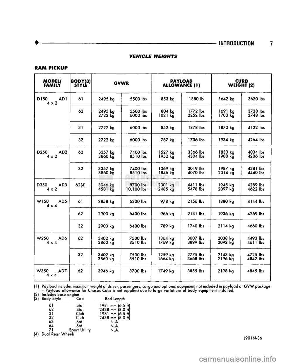
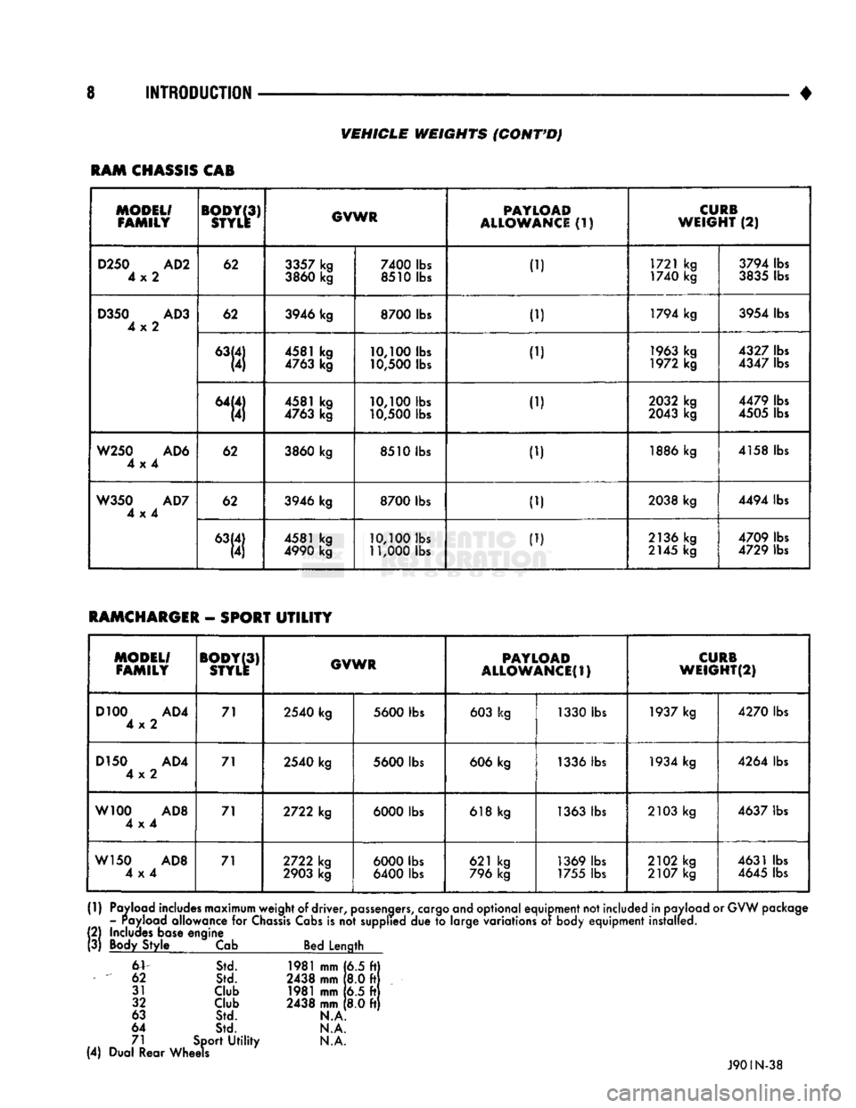
VEHICLE
WEIGHTS
The Vehicle Weights chart provides:
• The Gross Vehicle Weight Rating (GVWR),
• The payload
• The curb weight
for
each vehicle type/wheelbase
TRAILER
TOWING
SPECIFICATIONS
The Trailer Towing Specifications chart provides:
• The maximum trailer tongue weight
• The maximum trailer weight
• The maximum combined weight of the trailer/load/
towing vehicle with
a
specific engine/transmission/ axle combination.
VEHICLE
DIMENSION
The Vehicle Dimension chart provides
the
dimen
sions
for
each type
of
Ram Truck, Ram Chassis Cab
and Ramcharger vehicle.
ENGINE/TRANSMISSION/GVWR
The Engine/Transmission/GVWR chart provides
the maximum load data
for
each vehicle combina tion.
Page 12 of 1502
•
INTRODUCTION
7
VEHICLE
WEIGHTS
RAM
PICKUP
MODEL/
FAMILY
BODY
(3)
STYLE
GVWR
PAYLOAD
ALLOWANCE
(1)
CURB
WEIGHT
(2)
D150
AD1
4x2
61
2495
kg
5500
lbs
853
kg 1880 lb
1642 kg
3620
lbs
D150
AD1
4x2
62
2495
kg
2722
kg
5500
lbs
6000
lbs 804 kg
1021 kg 1772 lbs
2252
lbs 1691 kg
1700 kg
3728 lbs
3748 lbs
D150
AD1
4x2
31
2722
kg
6000
lbs 852 kg
1878 lbs 1870 kg
4122 lbs
D150
AD1
4x2
32
2722
kg
6000
lbs
787 kg 1736 lbs 1934 kg
4264 lbs
D250
AD2
4x2
62
3357
kg
3860
kg
7400
lbs
8510 lbs 1527 kg
1952 kg
3366 lbs
4304 lbs 1830 kg
1908 kg
4034 lbs
4206 lbs
D250
AD2
4x2
32
3357
kg
3860
kg
7400
lbs
8510 lbs 1369 kg
1846 kg
3019 lbs
4070
lbs 1987 kg
2014 kg 4381 lbs
4440
lbs
D350
AD3
4x2
62(4)
3946 kg
4581 kg
8700
lbs
10,100
lbs 2001 kg
2485
kg 4411 lbs
5478 lbs
1945
kg
2097
kg 4289 lbs
4622
lbs
W150
AD5
4x4
61
2858 kg
6300
lbs
978
kg
2156
lbs
1880 kg
4144 lbs
W150
AD5
4x4
62
2903
kg
6400
lbs
966
kg
2131 lbs
1936 kg 4269 lbs
W150
AD5
4x4
32
2903
kg
6400
lbs 789 kg
1740 lbs 2114 kg
4660
lbs
W250
AD6
4x4
62
3402
kg
3860
kg
7500
lbs
8510 lbs 1364 kg
1769 kg
3007
lbs
3899 lbs 2038 kg
2092
kg
4493
lbs
4611 lbs
W250
AD6
4x4
32
3402
kg
3860
kg
7500
lbs
8510 lbs 1259 kg
1664 kg
2775
lbs
3668 lbs
2143
kg
2196 kg
4725
lbs
4842
lbs
W350
AD7
4x4
62
3946 kg
8700
lbs 1749 kg
3855
lbs 2198 kg
4845
lbs
(1)
Payload
includes
maximum
weight
of
driver,
passengers,
cargo
and
optional
equipment
not
included
in
pavload
or
GVW
package
-
rayload
allowance
for
Chassis
Cabs
is
not supplied due to
large
variations
or
body
equipment
installed.
(2)
Includes
base
engine
(3)
Body
Style
Cab
Bed
Length
61
Std. 1981
mm
(6.5 ft
62 Std. 2438
mm
8.0 ft
31
Club
1981 mm 6.5 ft
32
Club
2438
mm
8.0 ft
63
Std. N.A
64
Std. N.A.
71
Sport
Utility N.A.
(4)
Dual
Rear
Wheels
J90IN-36
Page 13 of 1502
8 INTRODUCTION
•
VEHICLE
WEIGHTS
(CONT'D)
RAM
CHASSIS
CAB
MODEL/
FAMILY
BODY(3)
STYLE
GVWR
PAYLOAD
ALLOWANCE
(1)
CURB
WEIGHT
(2)
D250
AD2
4x2
62
3357
kg
3860
kg
7400
lbs
8510 lbs 1721 kg
1740 kg
3794 lbs
3835
lbs
D350
AD3
4x2
62
3946 kg
8700
lbs
ID
1794 kg
3954 lbs
D350
AD3
4x2
4581 kg
4763
kg
10,100
lbs
10,500
lbs
..,
1963
kg
1972 kg
4327
lbs
4347
lbs
D350
AD3
4x2
"111 4581 kg
4763
kg
10,100
lbs
10,500
lbs
1.1
2032
kg
2043
kg 4479 lbs
4505
lbs
W250
AD6
4x4
62
3860
kg
8510 lbs
1.) 1886 kg
4158 lbs
W350
AD7
4x4
62
3946 kg
8700
lbs
ID
2038 kg
4494 lbs
W350
AD7
4x4
4581 kg
4990
kg
10,100
lbs
11,000
lbs
ID
2136 kg
2145
kg 4709 lbs
4729 lbs
RAMCHARGER
-
SPORT
UTILITY
MODEL/
FAMILY
BODY(3)
STYLE
GVWR
PAYLOAD
ALLOWANCES)
CURB
WEIGHT(2)
D100
AD4
4x2 71
2540
kg
5600
lbs
603
kg 1330 lbs
1937
kg
4270
lbs
D150
AD4
4x2 71
2540
kg
5600
lbs
606
kg
1336
lbs
1934
kg
4264
lbs
W100
AD8
4x4 71
2722
kg
6000
lbs
618
kg
1363
lbs
2103
kg
4637
lbs
W150
AD8
4x4 71
2722
kg
2903
kg
6000
lbs
6400
lbs 621 kg
796
kg
1369
lbs
1755
lbs
2102
kg
2107
kg
4631
lbs
4645
lbs
(1)
Payload includes maximum weight
of
driver,
passengers,
cargo and optional equipment not included in payload
or
GVW package - Payload allowance
for
Chassis
Cabs
is
not
supplied
due to
large variations
of
body equipment installed.
!
2)
Includes base engine
3)
Body Style
Cab
Bed Length
6V
Std.
1981
mm
[6.5 ft)
62
Std.
2438
mm
8.0 ft
31
Club
1981
mm
6.5 ft
32
Club
2438
mm
8.0 ft
63
Std.
N.A
64
Std.
N.A.
71 Sport
Utility N.A.
(4) Dual Rear Wheels
J90IN-38
Page 41 of 1502
0
- 22
LUBRICATION
AND
MAINTENANCE
DRIVETRAIN
INDEX
page
Axles
25
Clutch
and
Brake Pedal
Bushings
............ 22
Clutch Master Cylinder
22
Drive Shafts
26
page
Front Axle U-Joint
and
Pivot Bearings
......... 26
Transfer
Case
(4WD
Vehicles)
. . ........ 24
Transmissions
. 22
CLUTCH
AND
BRAKE PEDAL
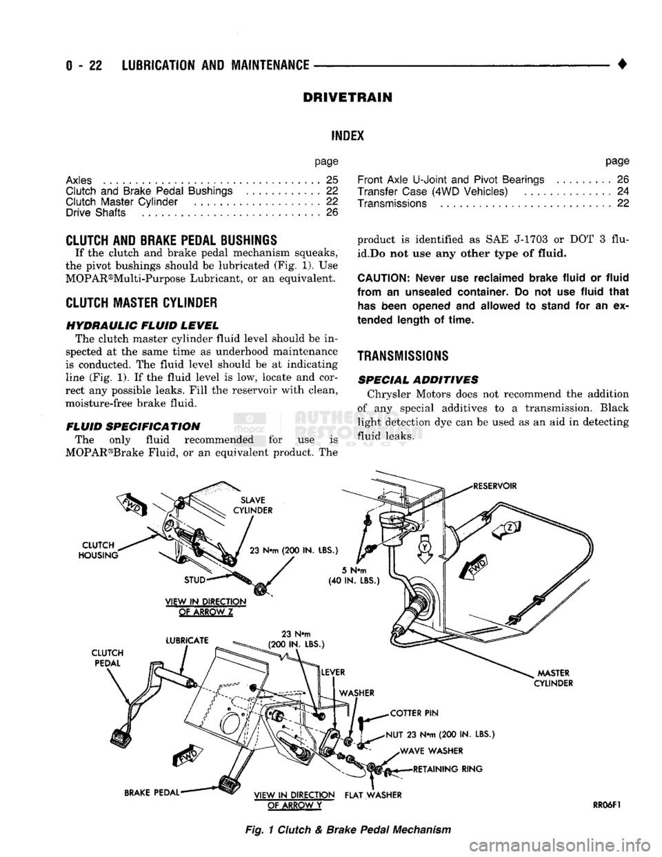
If the clutch and brake pedal mechanism squeaks,
the pivot bushings should be lubricated (Fig. 1). Use
MOPAR®Multi-Purpose Lubricant, or an equivalent.
CLUTCH
MASTER CYLINDER
HYDRAULIC FLUID LEVEL The clutch master cylinder fluid level should be in
spected at the same time as underhood maintenance
is conducted. The fluid level should be at indicating
line (Fig. 1). If the fluid level is low, locate and cor
rect any possible leaks. Fill the reservoir with clean,
moisture-free brake fluid.
FLUID SPECIFICATION The only fluid recommended for use is
MOPAR®Brake Fluid, or an equivalent product. The
SLAVE
CYLINDER
CLUTCH
HOUSING
23
N«m
(200 IN.
LBS.)
product is identified as SAE J-1703 or DOT 3 flu
id.Do not use any other type of
fluid.
CAUTION:
Never
use
reclaimed brake fluid
or
fluid
from
an
unsealed container.
Do not use
fluid that
has
been opened
and
allowed
to
stand
for an ex
tended length
of
time.
TRANSMISSIONS
SPECIAL ADDITIVES Chrysler Motors does not recommend the addition
of any special additives to a transmission. Black
light detection dye can be used as an aid in detecting
fluid leaks.
RESERVOIR
STUD
VIEW
IN
DIRECTION
GtAKBQWZ
LUBRICATE
CLUTCH
PEDAL
23 N#m
(200 IN. LBS.)
5
N«m
(40 IN.
LBS
MASTER
CYLINDER
COTTER
PIN
NUT
23 N*m (200 IN.
LBS.) WAVE WASHER RETAINING RING
BRAKE
PEDAL VIEW
IN
DIRECTION FLAT WASHER
OF ARROW
Y
RR06F1
Fig.
1
Clutch
& Brake
Pedal
Mechanism
Page 50 of 1502
•
LUBRICATION
AND
MAINTENANCE
0 - 31
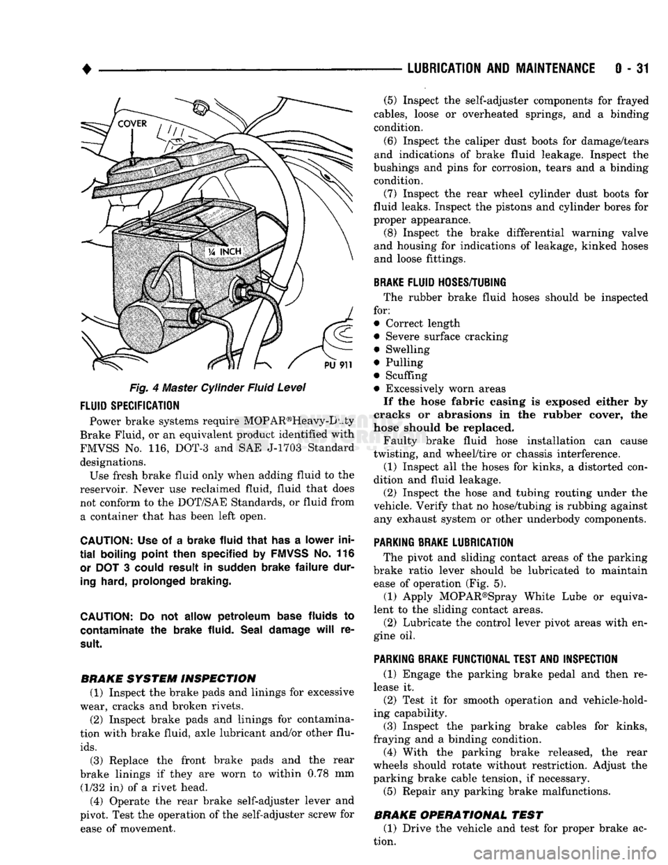
Fig. 4 Master Cylinder Fluid Level
FLUID
SPECIFICATION
Power brake systems require MOP AR®Heavy-D uty
Brake Fluid, or an equivalent product identified with
FMVSS No. 116, DOT-3 and SAE J-1703 Standard designations. Use fresh brake fluid only when adding fluid to the
reservoir. Never use reclaimed fluid, fluid that does not conform to the DOT/SAE Standards, or fluid from a container that has been left open.
CAUTION:
Use of a
brake fluid that
has a
lower ini
tial
boiling point then specified
by
FMVSS
No. 116
or
DOT 3
could result
in
sudden brake failure dur
ing
hard, prolonged braking.
CAUTION:
Do not
allow petroleum base
fluids
to
contaminate
the
brake fluid. Seal damage
will
re
sult.
BRAKE SYSTEM INSPECTION (1) Inspect the brake pads and linings for excessive
wear, cracks and broken rivets.
(2) Inspect brake pads and linings for contamina
tion with brake fluid, axle lubricant and/or other flu
ids.
(3) Replace the front brake pads and the rear
brake linings if they are worn to within 0.78 mm (1/32 in) of a rivet head.
(4) Operate the rear brake self-adjuster lever and
pivot. Test the operation of the self-adjuster screw for ease of movement. (5) Inspect the self-adjuster components for frayed
cables, loose or overheated springs, and a binding
condition.
(6) Inspect the caliper dust boots for damage/tears
and indications of brake fluid leakage. Inspect the
bushings and pins for corrosion, tears and a binding condition.
(7) Inspect the rear wheel cylinder dust boots for
fluid leaks. Inspect the pistons and cylinder bores for
proper appearance. (8) Inspect the brake differential warning valve
and housing for indications of leakage, kinked hoses and loose fittings.
BRAKE
FLUID
HOSES/TUBING
The rubber brake fluid hoses should be inspected
for:
• Correct length
• Severe surface cracking
• Swelling
• Pulling
• Scuffing
• Excessively worn areas If the hose fabric casing is exposed either by
cracks or abrasions in the rubber cover, the
hose should be replaced.
Faulty brake fluid hose installation can cause
twisting, and wheel/tire or chassis interference.
(1) Inspect all the hoses for kinks, a distorted con
dition and fluid leakage. (2) Inspect the hose and tubing routing under the
vehicle. Verify that no hose/tubing is rubbing against any exhaust system or other underbody components.
PARKING
BRAKE
LUBRICATION
The pivot and sliding contact areas of the parking
brake ratio lever should be lubricated to maintain ease of operation (Fig. 5).
(1) Apply MOPAR®Spray White Lube or equiva
lent to the sliding contact areas.
(2) Lubricate the control lever pivot areas with en
gine oil.
PARKING
BRAKE
FUNCTIONAL
TEST
AND
INSPECTION
(1) Engage the parking brake pedal and then re
lease it. (2) Test it for smooth operation and vehicle-hold
ing capability.
(3) Inspect the parking brake cables for kinks,
fraying and a binding condition. (4) With the parking brake released, the rear
wheels should rotate without restriction. Adjust the
parking brake cable tension, if necessary.
(5) Repair any parking brake malfunctions.
BRAKE OPERATIONAL TEST (1) Drive the vehicle and test for proper brake ac
tion.
Page 193 of 1502
5
- 6
BRAKES
• (c) On diesel models, vacuum pump hose or
pump component may have malfunctioned. Check
pump output with vacuum gauge and repair as necessary. Refer to service procedures in Power
Booster/Vacuum Pump section.
(6) Rebuild booster vacuum reserve as follows: Re
lease brake pedal. Increase engine speed to 1500
rpm, close throttle and immediately turn off ignition. (7) Wait a minimum of 90 seconds and try brake ac
tion again. Booster should provide two or more vacuum assisted pedal applications. If vacuum assist is not pro
vided, perform booster and check valve vacuum tests.
Also check vacuum output on diesel models.
POWER
BOOSTER
CHECK
VALVE
TEST
(1) Disconnect vacuum hose from check valve.
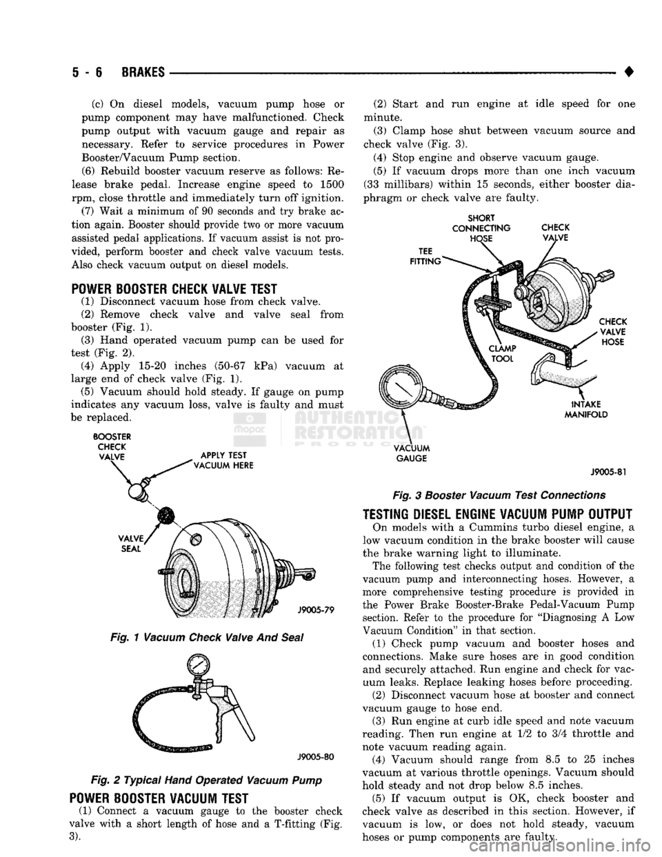
(2) Remove check valve and valve seal from
booster (Fig. 1). (3) Hand operated vacuum pump can be used for
test (Fig. 2). (4) Apply 15-20 inches (50-67 kPa) vacuum at
large end of check valve (Fig. 1). (5) Vacuum should hold steady. If gauge on pump
indicates any vacuum loss, valve is faulty and must
be replaced.
BOOSTER
CHECK
VALVE
APPLY
TEST
\
VACUUM
HERE
Fig.
1
Vacuum
Check
Vaive
And
Seal
J9005-80
Fig.
2 Typical
Hand
Operated
Vacuum
Pump
POWER
BOOSTER
VACUUM
TEST
(1) Connect a vacuum gauge to the booster check
valve with a short length of hose and a T-fitting (Fig.
3).
(2) Start and run engine at idle speed for one
minute.
(3) Clamp hose shut between vacuum source and
check valve (Fig. 3).
(4) Stop engine and observe vacuum gauge.
(5) If vacuum drops more than one inch vacuum
(33 millibars) within 15 seconds, either booster dia
phragm or check valve are faulty.
SHORT
CONNECTING
CHECK
VACUUM
GAUGE
J9005-81
Fig.
3
Booster
Vacuum
Test
Connections
TESTING
DIESEL
ENGINE
VACUUM
PUMP
OUTPUT
On models with a Cummins turbo diesel engine, a
low vacuum condition in the brake booster will cause
the brake warning light to illuminate. The following test checks output and condition of the
vacuum pump and interconnecting hoses. However, a
more comprehensive testing procedure is provided in
the Power Brake Booster-Brake Pedal-Vacuum Pump section. Refer to the procedure for "Diagnosing A Low
Vacuum Condition" in that section. (1) Check pump vacuum and booster hoses and
connections. Make sure hoses are in good condition and securely attached. Run engine and check for vac
uum leaks. Replace leaking hoses before proceeding. (2) Disconnect vacuum hose at booster and connect
vacuum gauge to hose end. (3) Run engine at curb idle speed and note vacuum
reading. Then run engine at 1/2 to 3/4 throttle and
note vacuum reading again. (4) Vacuum should range from 8.5 to 25 inches
vacuum at various throttle openings. Vacuum should
hold steady and not drop below 8.5 inches. (5) If vacuum output is OK, check booster and
check valve as described in this section. However, if
vacuum is low, or does not hold steady, vacuum
hoses or pump components are faulty.
Page 194 of 1502
•
BRAKES
i - 7
BRAKE
ADJUSTMENTS-BRAKE
BLEEDING
INDEX
page
Brake
Fluid and Level 7
Brake
System
Bleeding 8
Rear
Brake
Adjustment 7
BRAKE
FLUID
AND
LEWEL
RECOMMENDED
FLUID The only brake fluid recommended for AD models
is Mopar brake fluid, or an equivalent fluid meeting SAE
J1703
and DOT 3 standards.
Use new brake fluid only, to top off the master
cylinder or refill the system* Never use re
claimed fluid, fluid not meeting the
SAE/DOT
standards, fluid marked 70R1, or fluid from a
container that has been left open for any length
of time. Using non recommended or unspecified
fluid can result in brake failure after hard pro longed braking.
BRAKE
FLUID
LEWEL Always clean the master cylinder cover before
checking fluid level. If not cleaned, dirt from the
cover could enter the fluid. Also check the cover seal
and replace it if torn or distorted.
Correct fluid level is to the bottom of the ring in
dicators on models with a plastic reservoir and to
within 1/4 inch of the reservoir rim on all others. If necessary, add fluid to bring up to the proper level.
Note that on disc brake equipped vehicles, fluid level can be expected to fall as the brake pads wear.
BRAKE
FLUID
CONTAMINATION
Oil in the fluid will cause brake system rubber
seals to soften and swell. The seals may also become
porous and begin to deteriorate.
If fluid contamination is suspected, drain off a sam
ple from the master cylinder. A suction gun or simi lar device can be used for this purpose.
Empty the drained fluid into a glass container.
Contaminants in the fluid will cause the fluid to sep
arate into distinct layers. If contamination has oc
curred, the system rubber seals, hoses and cups must
be replaced and the system thoroughly flushed with clean brake fluid.
Remember that brake fluid tends to darken
over time. Do not confuse this normal condition
with contamination.
REAR
BRAKE
ADJUSTMENT
The rear drum brakes are equipped with a self ad
justing mechanism. Under normal circumstances, the only time adjustment is required is when the brake-
page
Stop
Light Switch Adjustment 9
Wheel
Nut Tightening 9
shoes are replaced; removed for access to other parts; or when one or both drums are replaced.
Adjustment can be performed with a standard
brake gauge or with adjusting tool C-3784.
ADJUSTMENT
WITH
STANDARD
BRAKE
GAUGE
(1) Verify that left/right automatic adjuster lever
and cable are properly connected and that parking
brakes are fully released. Be sure there is slack in cables.
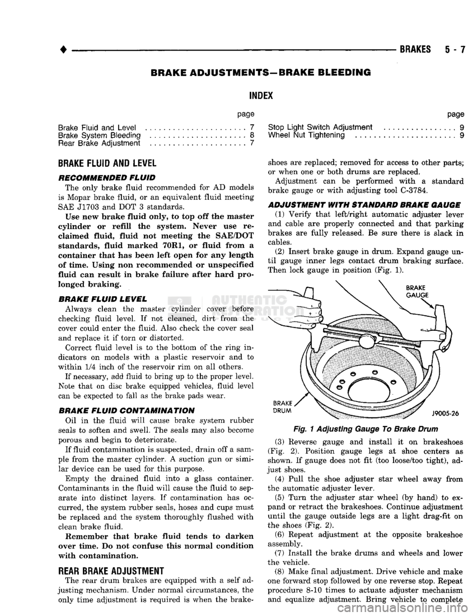
(2) Insert brake gauge in drum. Expand gauge un
til gauge inner legs contact drum braking surface. Then lock gauge in position (Fig. 1).
Fig.
1 Adjusting Gauge To Brake
Drum
(3) Reverse gauge and install it on brakeshoes
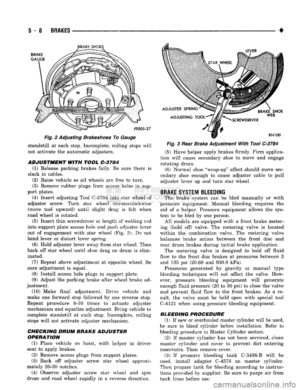
(Fig. 2). Position gauge legs at shoe centers as
shown. If gauge does not fit (too loose/too tight), ad
just shoes. (4) Pull the shoe adjuster star wheel away from
the automatic adjuster lever.
(5) Turn the adjuster star wheel (by hand) to ex
pand or retract the brakeshoes. Continue adjustment until the gauge outside legs are a light drag-fit on
the shoes (Fig. 2).
(6) Repeat adjustment at the opposite brakeshoe
assembly. (7) Install the brake drums and wheels and lower
the vehicle.
(8) Make final adjustment. Drive vehicle and make
one forward stop followed by one reverse stop. Repeat
procedure 8-10 times to actuate adjuster mechanism and equalize adjustment. Bring vehicle to complete
Page 195 of 1502
i - 8
BRAKES
•
BRAKE
SHOE'S
Fig. 2 Adjusting Brakeshoes To Gauge standstill at each stop. Incomplete, rolling stops will
not activate the automatic adjusters.
ADJUSTMENT
WITH
TOOL
C-3784
(1) Release parking brakes fully. Be sure there is
slack in cables. (2) Raise vehicle so all wheels are free to turn.
(3) Remove rubber plugs from access holes in sup
port plates. (4) Insert adjusting Tool
0-3784
into star wheel of
adjuster screw. Turn star wheel counterclockwise
(move tool upward) until slight drag is felt when
road wheel is rotated.
(5)
Insert thin screwdriver or length of welding rod
into support plate access hole and push adjuster lever
out of engagement with star wheel (Fig. 3). Do not
bend lever or distort lever spring.
(6) Hold adjuster lever away from star wheel. Then
back off star wheel until shoe drag on drum is elim inated.
(7) Repeat above adjustment at opposite wheel. Be
sure adjustment is equal. (8) Install access hole plugs in support plate.
(9) Adjust the parking brake after wheel brake ad
justment.
(10) Make final adjustment. Drive vehicle and
make one forward stop followed by one reverse stop.
Repeat procedure 8-10 times to actuate adjuster
mechanism and equalize adjustment. Bring vehicle to
complete standstill at each stop. Incomplete, rolling stops will not activate adjuster mechanism.
CHECKING DRUM
BRAKE ADJUSTER
OPERATION
(1) Place vehicle on hoist, with helper in driver
seat to apply brakes.
(2) Remove access plugs from support plates.
(3) Back off adjuster screw star wheel approxi
mately 20-30 notches. (4) Observe adjuster screw star wheel and spin
drum and road wheel rapidly in a reverse direction. Fig. 3 Rear Brake Adjustment With Tool
C-3784
(5) Have helper apply brakes firmly. Firm applica
tion will cause secondary shoe to move and engage rotating drum.
(6) Normal shoe "wrap-up" effect should move sec
ondary shoe enough to cause adjuster cable to pull adjuster lever up and turn star wheel.
BRAKE
SYSTEM BLEEDING
The brake system can be bled manually or with
pressure equipment. Manual bleeding requires the aid of a helper. Pressure equipment allows the sys
tem to be bled by one person. All models are equipped with a front brake meter
ing (hold off) valve. The metering valve is located
within the combination valve. The metering valve balances brake action between the front disc and
rear drum brakes during initial brake application. The metering valve is designed to hold off fluid
flow to the front disc brakes at pressures between 3 and 135 psi (20.68 and 930.8 kPa). Pressures generated by gravity or manual type
bleeding techniques will not affect the valve. How ever, pressure bleeding equipment will generate
enough fluid pressure (20 to 30 psi) to close the valve and prevent fluid flow to the front brakes. As a re
sult, the valve must be held open with special tool
C-4121 when using pressure bleeding equipment.
BLEEDING PROCEDURE (1) If new or overhauled master cylinder will be used,
be sure to bleed cylinder before installation. Refer to
bleeding procedure in Master Cylinder section. (2) If master cylinder has not been serviced, clean
master cylinder and cover to prevent dirt entering
reservoirs. Then remove cover.
(3) If pressure bleeding tank C-3496-B will be
used, install adapter C-4578 on master cylinder.
Then prepare tank for bleeding according to instruc
tions provided by supplier. Be sure to purge air from
tank lines before use.