1993 DODGE TRUCK length
[x] Cancel search: lengthPage 201 of 1502
5
- 14
BRAKES
•
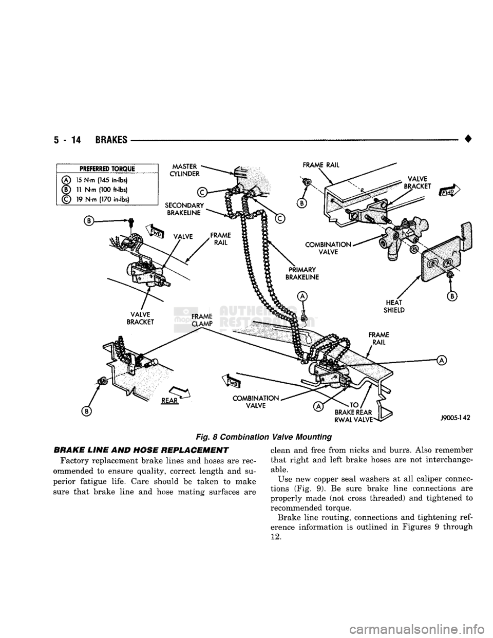
Fig. 8 Combinat
BRAKE LINE AND HOSE REPLACEMENT Factory replacement brake lines and hoses are rec
ommended to ensure quality, correct length and su
perior fatigue life. Care should be taken to make sure that brake line and hose mating surfaces are
Valve
Mounting
clean and free from nicks and burrs. Also remember
that right and left brake hoses are not interchange
able.
Use new copper seal washers at all caliper connec
tions (Fig. 9). Be sure brake line connections are
properly made (not cross threaded) and tightened to recommended torque.
Brake line routing, connections and tightening
ref
erence information is outlined in Figures 9 through
12.
Page 289 of 1502
7 - 18
COOLING
SYSTEM
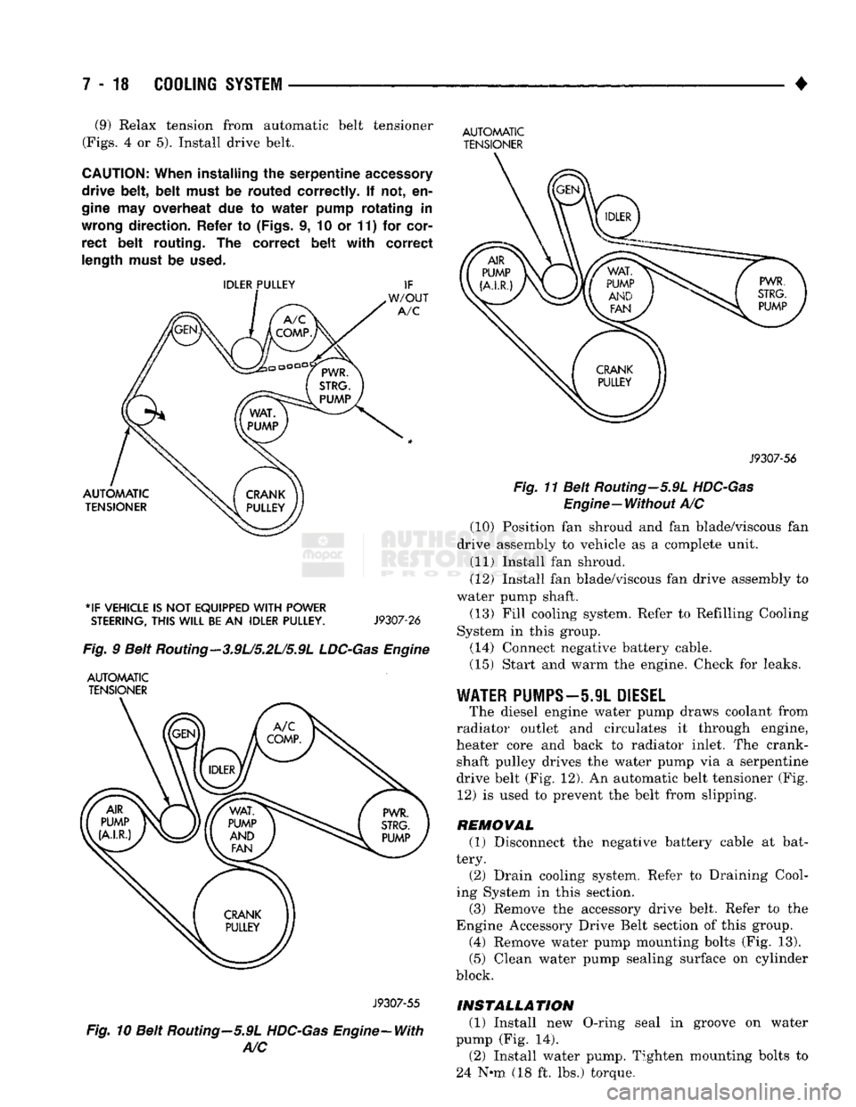
• (9) Relax tension from automatic belt tensioner
(Figs.
4 or 5). Install drive belt.
CAUTION:
When
installing
the
serpentine
accessory
drive
belt, belt
must
be
routed
correctly.
If not, en
gine
may
overheat
due to
water
pump
rotating
in
wrong
direction.
Refer
to
(Figs,
i, 10 or 11) for
cor
rect
belt
routing.
The
correct
belt with
correct
length
must
be
used.
*IF
VEHICLE
IS NOT
EQUIPPED
WITH
POWER
STEERING,
THIS
WILL
BE
AN
IDLER
PULLEY.
J9307-26
Fig.
9 Belt Routing—3.9U5.2L/5.9L
LDC-Gas
Engine
AUTOMATIC
TENSIONER
AUTOMATIC
TENSIONER
J9307-56
Fig.
11 Belt Routing—5.9L
HDC-Gas
Engine—Without
A/C (10) Position fan shroud and fan blade/viscous fan
drive assembly to vehicle as a complete unit. (11) Install fan shroud.
(12) Install fan blade/viscous fan drive assembly to
water pump shaft.
(13) Fill cooling system. Refer to Refilling Cooling
System in this group. (14) Connect negative battery cable.
(15) Start and warm the engine. Check for leaks.
WATER
PUMPS—5.9L
DIESEL
The diesel engine water pump draws coolant from
radiator outlet and circulates it through engine,
heater core and back to radiator inlet. The crank shaft pulley drives the water pump via a serpentine
drive belt (Fig. 12). An automatic belt tensioner (Fig. 12) is used to prevent the belt from slipping.
REMOVAL (1) Disconnect the negative battery cable at bat
tery. (2) Drain cooling system. Refer to Draining Cool
ing System in this section.
(3) Remove the accessory drive belt. Refer to the
Engine Accessory Drive Belt section of this group. (4) Remove water pump mounting bolts (Fig. 13).
(5) Clean water pump sealing surface on cylinder
block.
J9307-55
Fig.
10 Belt Routing—5.9L
HDC-Gas
Engine-With
A/C
INSTALLATION
(1) Install new O-ring seal in groove on water
pump (Fig. 14). (2) Install water pump. Tighten mounting bolts to
24 N-m (18 ft. lbs.) torque.
Page 293 of 1502
7 - 22
COOLING
SYSTEM
•
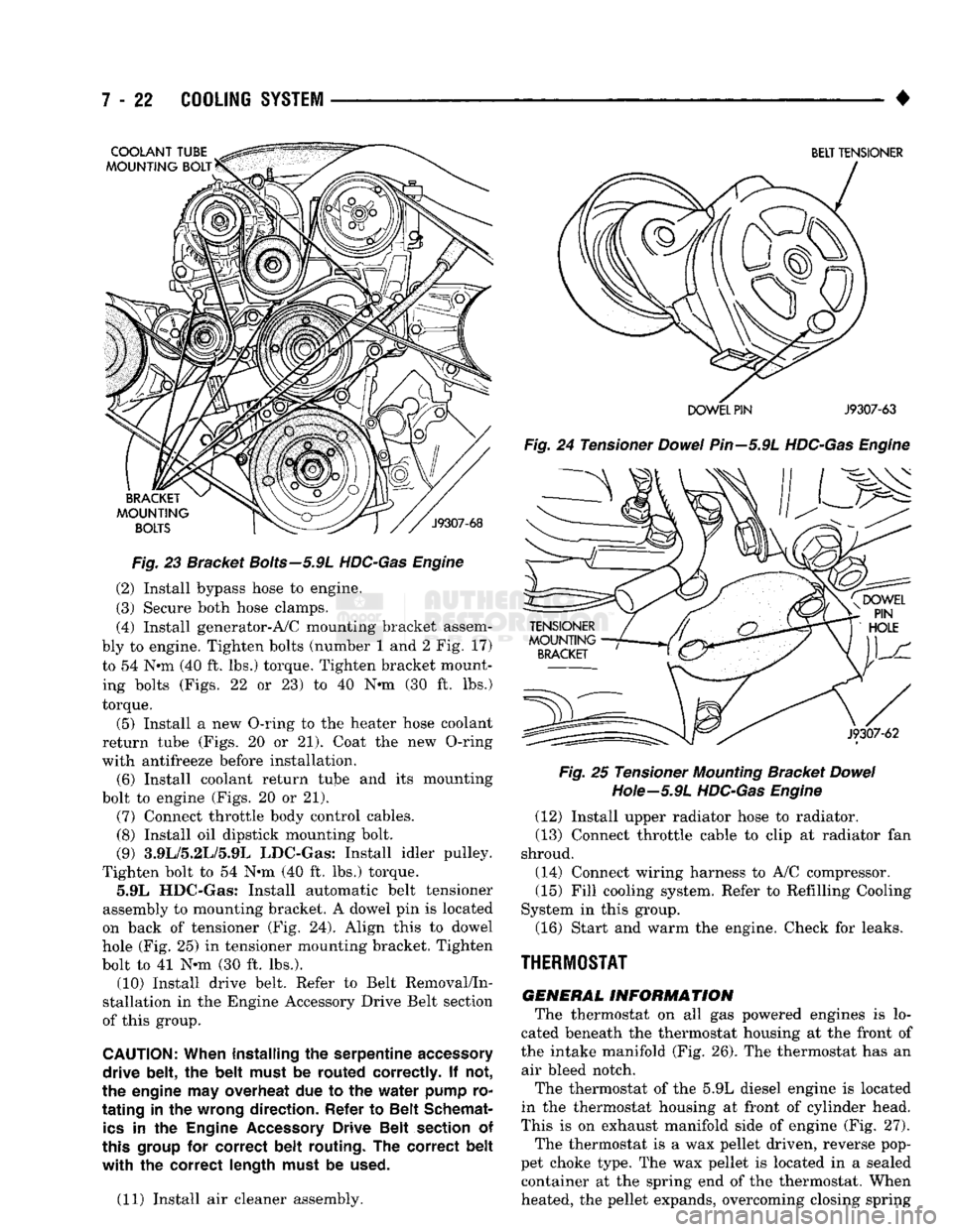
Fig.
23 Bracket
Bolts—5.9L
HDC-Gas Engine
(2) Install bypass hose to engine.
(3) Secure both hose clamps.
(4) Install generator-A/C mounting bracket assem
bly to engine. Tighten bolts (number 1 and 2 Fig. 17)
to 54 Nnn (40 ft. lbs.) torque. Tighten bracket mount ing bolts (Figs. 22 or 23) to 40 N-m (30 ft. lbs.)
torque.
(5) Install a new O-ring to the heater hose coolant
return tube (Figs. 20 or 21). Coat the new O-ring
with antifreeze before installation. (6) Install coolant return tube and its mounting
bolt to engine (Figs. 20 or 21). (7) Connect throttle body control cables.
(8) Install oil dipstick mounting bolt.
(9) 3.9L/5.2L/5.9L LDC-Gas: Install idler pulley.
Tighten bolt to 54 Nnn (40 ft. lbs.) torque. 5.9L HDC-Gas: Install automatic belt tensioner
assembly to mounting bracket. A dowel pin is located
on back of tensioner (Fig. 24). Align this to dowel
hole (Fig. 25) in tensioner mounting bracket. Tighten
bolt to 41 N-m (30 ft. lbs.). (10) Install drive belt. Refer to Belt Removal/In
stallation in the Engine Accessory Drive Belt section
of this group.
CAUTION:
When installing
the
serpentine
accessory
drive belt,
the
belt must
be
routed correctly.
If not,
the engine
may
overheat
due to the
water pump
ro
tating
in the
wrong direction. Refer
to
Belt Schemat
ics
in the
Engine
Accessory
Drive Belt section
of
this
group
for
correct belt routing.
The
correct belt
with the
correct length must
be
used.
(11) Install air cleaner assembly.
BELT TENSIONER
DOWEL PIN
J9307-63
Fig.
24 Tensioner
Dowel
Pin—5.9L
HDC-Gas Engine Fig.
25 Tensioner
Mounting
Bracket
Dowel
Hote—5.9L
HDC-Gas Engine
(12) Install upper radiator hose to radiator.
(13) Connect throttle cable to clip at radiator fan
shroud.
(14) Connect wiring harness to A/C compressor. (15) Fill cooling system. Refer to Refilling Cooling
System in this group.
(16) Start and warm the engine. Check for leaks.
THERMOSTAT
GENERAL
INFORMATION
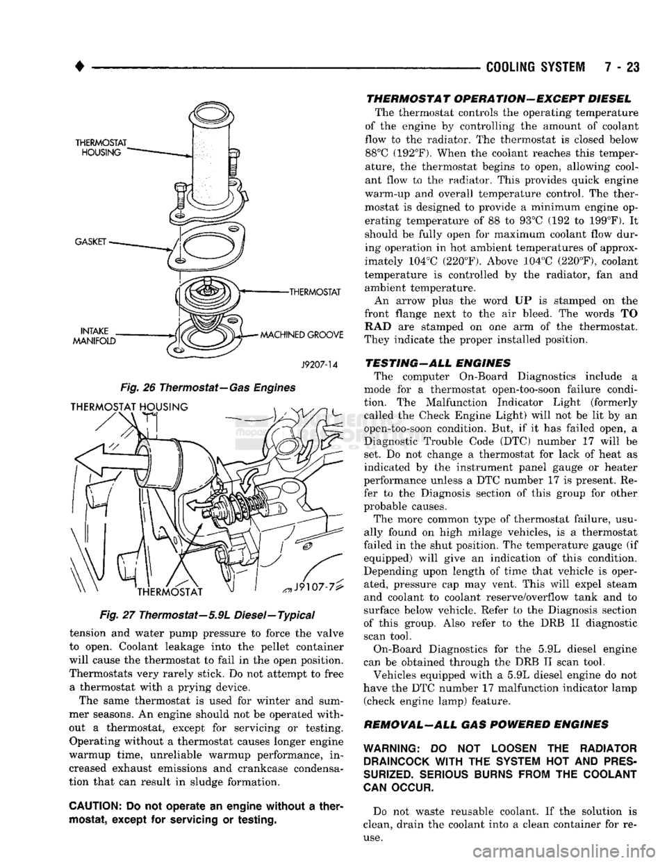
The thermostat on all gas powered engines is lo
cated beneath the thermostat housing at the front of
the intake manifold (Fig. 26). The thermostat has an air bleed notch.
The thermostat of the 5.9L diesel engine is located
in the thermostat housing at front of cylinder head.
This is on exhaust manifold side of engine (Fig. 27). The thermostat is a wax pellet driven, reverse pop
pet choke type. The wax pellet is located in a sealed container at the spring end of the thermostat. When
heated, the pellet expands, overcoming closing spring
Page 294 of 1502
•
COOLING SYSTEM
7 - 23
•THERMOSTAT
MACHINED GROOVE
J9207-14
Fig.
26
Thermostat—
Gas Engines
Fig.
27 Thermostat—5.9L Diesel—Typical
tension and water pump pressure to force the valve
to open. Coolant leakage into the pellet container
will cause the thermostat to fail in the open position.
Thermostats very rarely stick. Do not attempt to free a thermostat with a prying device.
The same thermostat is used for winter and sum
mer seasons. An engine should not be operated with
out a thermostat, except for servicing or testing. Operating without a thermostat causes longer engine
warmup time, unreliable warmup performance, in
creased exhaust emissions and crankcase condensa
tion that can result in sludge formation.
CAUTION:
Do not operate an engine without a
ther
mostat,
except for
servicing
or
testing.
THERMOSTAT OPERATION-EXCEPT DIESEL
The thermostat controls the operating temperature
of the engine by controlling the amount of coolant
flow to the radiator. The thermostat is closed below 88°C (192°F). When the coolant reaches this temper
ature, the thermostat begins to open, allowing cool
ant flow to the radiator. This provides quick engine
warm-up and overall temperature control. The ther
mostat is designed to provide a minimum engine op erating temperature of 88 to 93°C (192 to 199°F). It
should be fully open for maximum coolant flow dur
ing operation in hot ambient temperatures of approx
imately 104°C (220°F). Above 104°C (220°F), coolant
temperature is controlled by the radiator, fan and ambient temperature.
An arrow plus the word UP is stamped on the
front flange next to the air bleed. The words TO RAD are stamped on one arm of the thermostat.
They indicate the proper installed position.
TESTING-ALL ENGINES The computer On-Board Diagnostics include a
mode for a thermostat open-too-soon failure condi
tion. The Malfunction Indicator Light (formerly called the Check Engine Light) will not be lit by an
open-too-soon condition. But, if it has failed open, a
Diagnostic Trouble Code (DTC) number 17 will be
set. Do not change a thermostat for lack of heat as
indicated by the instrument panel gauge or heater
performance unless a DTC number 17 is present. Re
fer to the Diagnosis section of this group for other
probable causes.
The more common type of thermostat failure, usu
ally found on high milage vehicles, is a thermostat
failed in the shut position. The temperature gauge (if equipped) will give an indication of this condition.
Depending upon length of time that vehicle is oper
ated, pressure cap may vent. This will expel steam
and coolant to coolant reserve/overflow tank and to
surface below vehicle. Refer to the Diagnosis section
of this group. Also refer to the DRB II diagnostic
scan tool.
On-Board Diagnostics for the 5.9L diesel engine
can be obtained through the DRB II scan tool.
Vehicles equipped with a 5.9L diesel engine do not
have the DTC number 17 malfunction indicator lamp (check engine lamp) feature.
REMOVAL-ALL GAS POWERED ENGINES
WARNING:
DO NOT
LOOSEN
THE
RADIATOR DRAINCOCK
WITH
THE
SYSTEM
HOT AND
PRES
SURIZED.
SERIOUS BURNS FROM
THE
COOLANT
CAN
OCCUR.
Do not waste reusable coolant. If the solution is
clean, drain the coolant into a clean container for re
use.
Page 296 of 1502
•
COOLING
SYSTEM
7 - 25
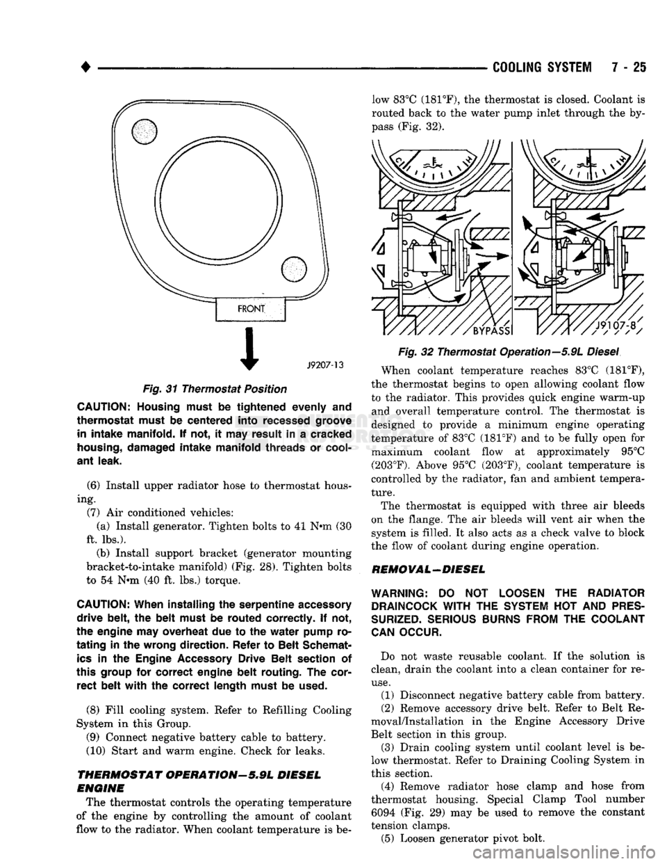
Fig.
31 Thermostat Position
CAUTION; Housing must
be
tightened
evenly and
thermostat must
be
centered into recessed groove in
intake manifold. If not, it may
result
in a
cracked
housing,
damaged intake manifold threads
or
cool
ant
leak.
(6) Install upper radiator hose to thermostat hous
ing. (7) Air conditioned vehicles: (a) Install generator. Tighten bolts to 41 N-m (30
ft. lbs.). (b) Install support bracket (generator mounting
bracket-to-intake manifold) (Fig. 28). Tighten bolts
to 54 N-m (40 ft. lbs.) torque.
CAUTION:
When installing
the
serpentine accessory
drive belt,
the
belt must
be
routed correctly.
If not,
the engine
may overheat due to the
water pump
ro
tating in the
wrong direction. Refer
to
Belt Schemat
ics
in the
Engine
Accessory
Drive Belt section
of
this group
for
correct engine belt routing.
The
cor rect belt with
the
correct length must
be
used.
(8) Fill cooling system. Refer to Refilling Cooling
System in this Group. (9) Connect negative battery cable to battery.
(10) Start and warm engine. Check for leaks.
THERMOSTAT OPERATIONr-5.9L DIESEL
ENGINE
The thermostat controls the operating temperature
of the engine by controlling the amount of coolant
flow to the radiator. When coolant temperature is be low 83°C (181°F), the thermostat is closed. Coolant is
routed back to the water pump inlet through the by
pass (Fig. 32).
Fig.
32 Thermostat Operation—5.9L
Diesel
When coolant temperature reaches 83°C (181°F),
the thermostat begins to open allowing coolant flow
to the radiator. This provides quick engine warm-up and overall temperature control. The thermostat is
designed to provide a minimum engine operating
temperature of 83°C (181°F) and to be fully open for maximum coolant flow at approximately 95°C (203°F). Above 95°C (203°F), coolant temperature is
controlled by the radiator, fan and ambient tempera
ture.
The thermostat is equipped with three air bleeds
on the flange. The air bleeds will vent air when the system is filled. It also acts as a check valve to block
the flow of coolant during engine operation.
REMOVAL-DIESEL
WARNING:
DO NOT
LOOSEN
THE
RADIATOR
DRAINCOCK
WITH
THE
SYSTEM
HOT
AND
PRES
SURIZED.
SERIOUS
BURNS
FROM
THE
COOLANT
CAN
OCCUR.
Do not waste reusable coolant. If the solution is
clean, drain the coolant into a clean container for re
use.
(1) Disconnect negative battery cable from battery.
(2) Remove accessory drive belt. Refer to Belt Re
moval/Installation in the Engine Accessory Drive
Belt section in this group.
(3) Drain cooling system until coolant level is be
low thermostat. Refer to Draining Cooling System in
this section.
(4) Remove radiator hose clamp and hose from
thermostat housing. Special Clamp Tool number 6094 (Fig. 29) may be used to remove the constant
tension clamps.
(5) Loosen generator pivot bolt.
Page 314 of 1502
•
*IF VEHICLE IS NOT EQUIPPED
WITH
POWER
STEERING,
THIS
WILL
BE
AN
IDLER PULLEY.
J9307-26
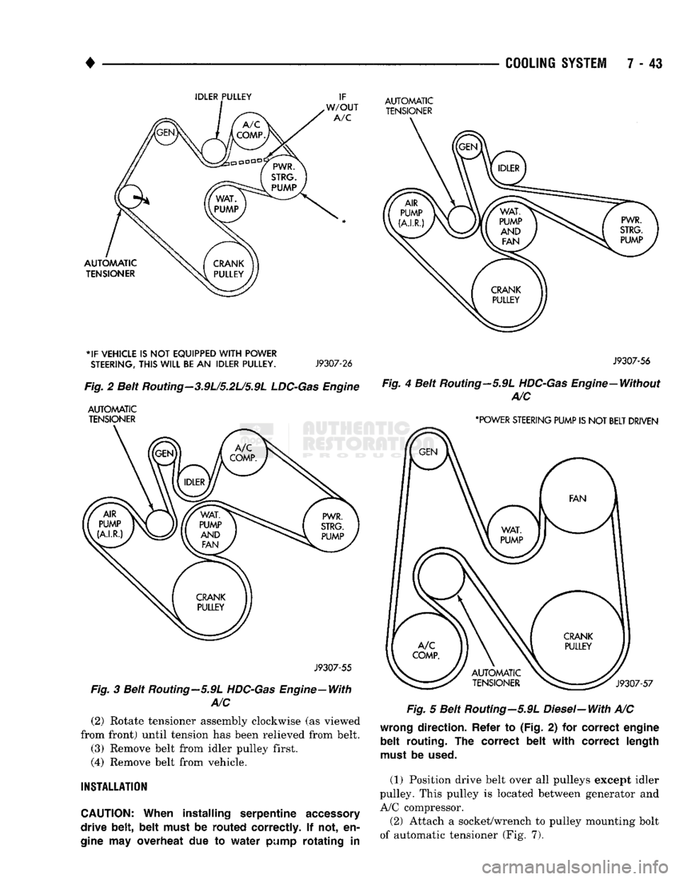
Fig.
2 Beit
Routing
- 3.9U5.2L/5.9L
LDC-Gas
Engine
AUTOMATIC TENSIONER
J9307-55
Fig.
3 Beit Routing—5.9L HDC-Gas Engine—With
A/C
(2)
Rotate tensioner assembly clockwise (as viewed
from front) until tension has been relieved from belt.
(3) Remove belt from idler pulley first.
(4)
Remove belt from vehicle.
INSTALLATION
CAUTION:
When
installing
serpentine accessory
drive
belt, belt
must
be
routed
correctly.
If not, en
gine
may
overheat
due to
water
pump
rotating in
COOLING
SYSTEM
7 - 43
AUTOMATIC TENSIONER
J9307-56
Fig.
4 Belt Routing—5.9L
HDC-Gas
Engine—Without A/C
'POWER STEERING PUMP IS
NOT
BELT DRIVEN
Fig.
5 Belt Routing-5.9L Diesel-With A/C
wrong
direction. Refer
to
(Fig.
2) for
correct engine
belt routing.
The
correct belt with correct length
must
be
used.
(1) Position drive belt over all pulleys except idler
pulley. This pulley is located between generator and
A/C compressor.
(2) Attach a socket/wrench to pulley mounting bolt
of automatic tensioner (Fig. 7).
Page 315 of 1502
7 - 44
COOLING
SYSTEM
•
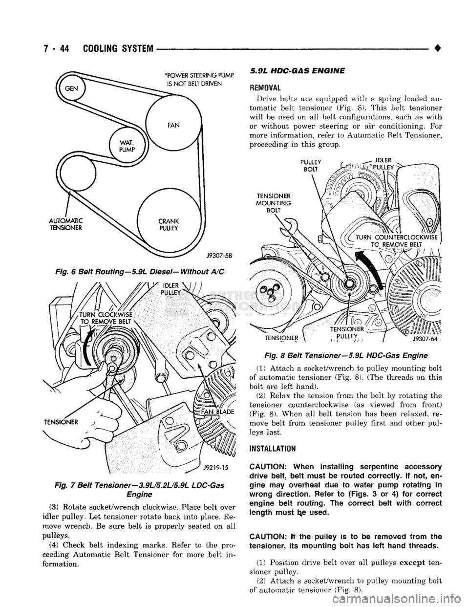
Fig.
6 Belt Routing-5.9L Diesel-Without A/C
Fig.
7 Belt Tensioner-3.9L/5.2U5.9L
LDC-Gas
Engine
(3)
Rotate socket/wrench clockwise. Place belt over
idler pulley. Let tensioner rotate back into place. Re
move wrench. Be sure belt is properly seated on all
pulleys.
(4)
Check belt indexing marks. Refer to the pro
ceeding Automatic Belt Tensioner for more belt in
formation. 5.9L
HDC-GAS
ENGINE
REMOVAL
Drive belts are equipped with a spring loaded au
tomatic belt tensioner (Fig. 8). This belt tensioner
will be used on all belt configurations, such as with or without power steering or air conditioning. For
more information, refer to Automatic Belt Tensioner,
proceeding in this group.
Fig.
8 Belt Tensioner—5.9L
HDC-Gas Engine
(1) Attach a socket/wrench to pulley mounting bolt
of automatic tensioner (Fig. 8). (The threads on this
bolt are left hand).
(2) Relax the tension from the belt by rotating the
tensioner counterclockwise (as viewed from front) (Fig. 8). When all belt tension has been relaxed, re
move belt from tensioner pulley first and other pul leys last.
INSTALLATION
CAUTION:
When installing serpentine
accessory
drive belt, belt must
be
routed correctly.
If not, en
gine
may
overheat
due to
water pump rotating
in
wrong
direction. Refer
to
(Figs.
3 or 4) for
correct
engine
belt routing.
The
correct belt with correct length must
t^e
used.
CAUTION:
if the
pulley
is to be
removed from
the
tensioner,
its
mounting bolt
has left
hand threads.
(1) Position drive belt over all pulleys except ten
sioner pulley. (2) Attach a socket/wrench to pulley mounting bolt
of automatic tensioner (Fig. 8).
Page 316 of 1502
•
COOLING
SYSTEM
7 - 45 (3) Rotate socket/wrench counterclockwise. Install
belt over tensioner pulley. Let tensioner rotate back into place. Remove wrench. Be sure belt is properly
seated on all pulleys.
5«9L
DIESEL ENGINE
REMOVAL
Drive belts on diesel engines are equipped with a
spring loaded automatic belt tensioner (Fig. 9). Fig
ure 9 displays the tensioner for vehicles without air conditioning.
This belt tensioner will be used on all belt config
urations, such as with or without air conditioning.
For more information, refer to Automatic Belt Ten sioner, proceeding in this group.
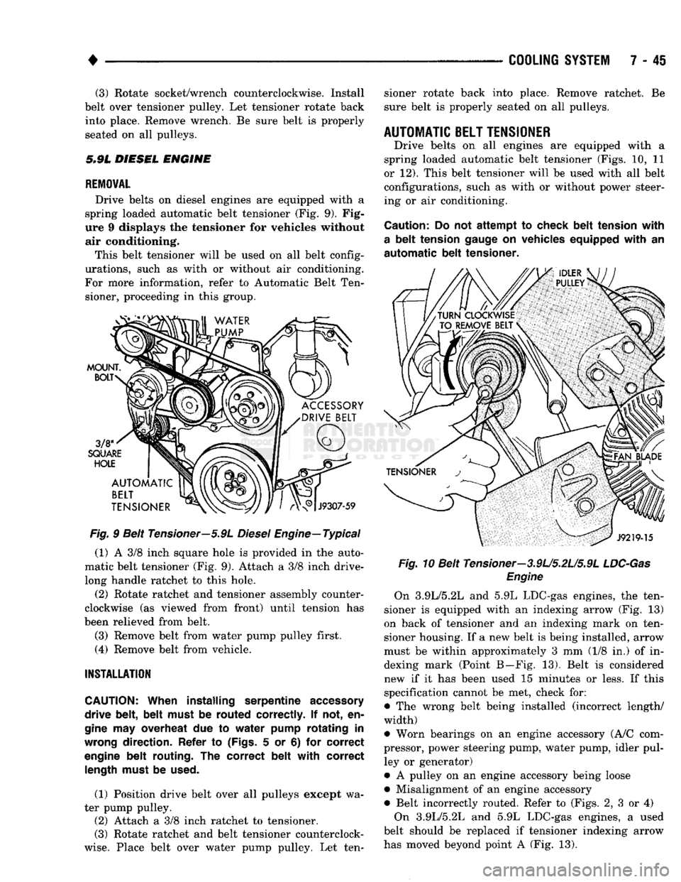
Fig.
9 Belt Tensioner—5.9L
Diesel
Engine—Typical
(1) A 3/8 inch square hole is provided in the auto
matic belt tensioner (Fig. 9). Attach a 3/8 inch drive-
long handle ratchet to this hole.
(2) Rotate ratchet and tensioner assembly counter
clockwise (as viewed from front) until tension has
been relieved from belt.
(3) Remove belt from water pump pulley first.
(4) Remove belt from vehicle.
INSTALLATION
CAUTION:
When installing serpentine
accessory
drive belt, belt must
be
routed correctly.
If not, en
gine
may
overheat
due to
water pump rotating
in
wrong
direction. Refer
to
(Figs.
5 or 6) for
correct
engine
belt routing.
The
correct belt with correct
length
must
be
used.
(1) Position drive belt over all pulleys except wa
ter pump pulley. (2) Attach a 3/8 inch ratchet to tensioner.
(3) Rotate ratchet and belt tensioner counterclock
wise.
Place belt over water pump pulley. Let ten sioner rotate back into place. Remove ratchet. Be
sure belt is properly seated on all pulleys.
AUTOMATIC
BELT
TENSIONER
Drive belts on all engines are equipped with a
spring loaded automatic belt tensioner (Figs. 10, 11
or 12). This belt tensioner will be used with all belt configurations, such as with or without power steer
ing or air conditioning.
Caution:
Do not
attempt
to
check belt tension with
a
belt tension
gauge
on
vehicles equipped with
an
automatic
belt tensioner. Fig.
10 Belt Tensioner—3.9U5.2U5.9L
LDC-Gas
Engine
On 3.9L/5.2L and 5.9L LDC-gas engines, the ten
sioner is equipped with an indexing arrow (Fig. 13)
on back of tensioner and an indexing mark on ten
sioner housing. If a new belt is being installed, arrow
must be within approximately 3 mm (1/8 in.) of in dexing mark (Point B—Fig. 13). Belt is considered
new if it has been used 15 minutes or less. If this
specification cannot be met, check for:
• The wrong belt being installed (incorrect length/
width)
• Worn bearings on an engine accessory (A/C com
pressor, power steering pump, water pump, idler pul ley or generator)
• A pulley on an engine accessory being loose
• Misalignment of an engine accessory
• Belt incorrectly routed. Refer to (Figs. 2, 3 or 4) On 3.9L/5.2L and 5.9L LDC-gas engines, a used
belt should be replaced if tensioner indexing arrow
has moved beyond point A (Fig. 13).