1993 DODGE TRUCK length
[x] Cancel search: lengthPage 339 of 1502
8A
- 18
ELECTRICAL
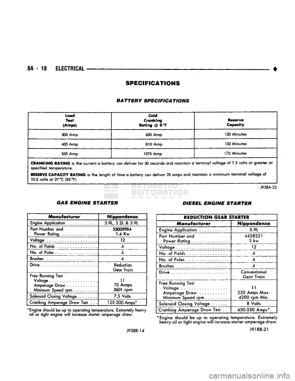
• BATTERY SPECIFICATIONS
Load
Test
(Amps)
Cold
Cranking
Rating @ 0°F Reserve
Capacity
300 Amp 600 Amp 120 Minutes
405 Amp 810 Amp 133 Minutes
535 Amp 1075 Amp 170 Minutes
CRANKING
RATING
is the
current
a
battery
can deliver for 30
seconds
and maintain a
terminal
voltage of 7.2 volts or greater at specified
temperature.
RESERVE
CAPACITY RATING
is the length of
time
a
battery
can deliver 25 amps and maintain a minimum
terminal
voltage of 10.5 volts
at27°C
(80 °F).
J938A-25 GAS ENGINE STARTER
DIESEL ENGINE STARTER
Manufacturer
Nippondenso
Engine
Application 5.9L, 5.21 e\ 3.9L
Part Number and
53005984
Power Rating 1.4 Kw
Voltage 12
No.
of Fields 4
No.
of
Poles.
4
Brushes
4
Drive Reduction
Gear Train
Free
Running Test Voltage 11
Amperage Draw ............ 73
Amps
Minimum Speed rpm 3601 rpm
Solenoid
Closing
Voltage 7.5 Volts
Cranking Amperage Draw Test . . .
125-200
Amps*
*
Engine
should
be up to operating
temperature.
Extremely heavy oil or tight engine
will
increase
starter
amperage draw.
J938B-14
REDUCTION
GEAR
STARTER
Manufacturer
Nippondenso
Engine
Application 5.9L
Part Number and Power Rating ..............
4428221
3
kw
Voltage 12
No.
of Fields 4
No.
of
Poles
4
Brushes
.................... 4
Drive Conventional
Gear Train
Free
Running Test Voltage .
Amperage Draw
Minimum Speed rpm 11
220
Amps
Max.
4200
rpm Min.
Solenoid
Closing
Voltage. 8 Volts
Cranking Amperage Draw Test . .
450-550
Amps*
*
Engine
should be up to operating heavy oil or tight engine
will
increase
temperature.
Extremely
starter
amperage draw. J918B-21
SPECIFICATIONS
Page 348 of 1502
•
Fig.
3
Remove
or install
Wire
Connector
Assembly
CAUTION:
When
installing
serpentine
accessory
drive
belt,
the
belt
MUST
be
routed
correctly.
If not,
the engine may overheat due to the
water
pump ro
tating
in the wrong
direction.
Refer to Group 7 -
Cooling
System
for
correct
engine
belt
routing.
The
correct
belt
with
the
correct
length
must be
used
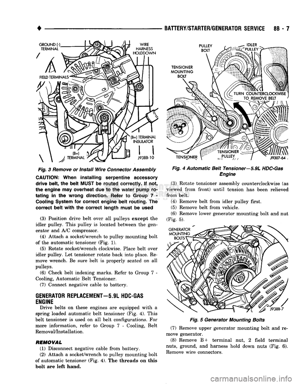
(3) Position drive belt over all pulleys except the
idler pulley. This pulley is located between the gen
erator and A/C compressor.
(4) Attach a socket/wrench to pulley mounting bolt
of the automatic tensioner (Fig. 1).
(5)
Rotate socket/wrench clockwise. Place belt over
idler pulley. Let tensioner rotate back into place. Re
move wrench. Be sure belt is properly seated on all
pulleys.
(6) Check belt indexing marks. Refer to Group 7 -
Cooling, Automatic Belt Tensioner.
(7) Connect negative cable to battery.
GENERATOR
REPLACEMENT—5.9L
HDC-GAS
ENGINE
Drive belts on these engines are equipped with a
spring loaded automatic belt tensioner (Fig. 4). This
belt tensioner is used on all belt configurations. For more information, refer to Group 7 - Cooling, Belt
Removal/Installation.
REMOVAL
(1) Disconnect negative cable from battery.
(2) Attach a socket/wrench to pulley mounting bolt
of automatic tensioner (Fig. 4). The threads on this
bolt are left hand.
BATTERY/STARTER/GENERATOR
SERVICE
8B - 7
Fig.
4 Automatic Belt Tensioner—5.9L
HDC-Gas
Engine
(3) Rotate tensioner assembly counterclockwise (as
viewed from front) until tension has been relieved
from belt.
(4) Remove belt from idler pulley first.
(5) Remove belt from vehicle.
(6) Remove lower generator mounting bolt and nut
(Fig. 5).
Fig.
5 Generator
Mounting
Bolts
(7) Remove upper generator mounting bolt and re
move generator.
(8) Remove B+ terminal nut, 2 field terminal
nuts,
ground, and harness hold down nuts (Fig. 6).
Remove wire connectors.
Page 349 of 1502
8B
- 8
BATTERY/STARTER/GENERATOR
SERVICE
•
Fig.
6
Remove
or Install
Wire
Connector
Assembly
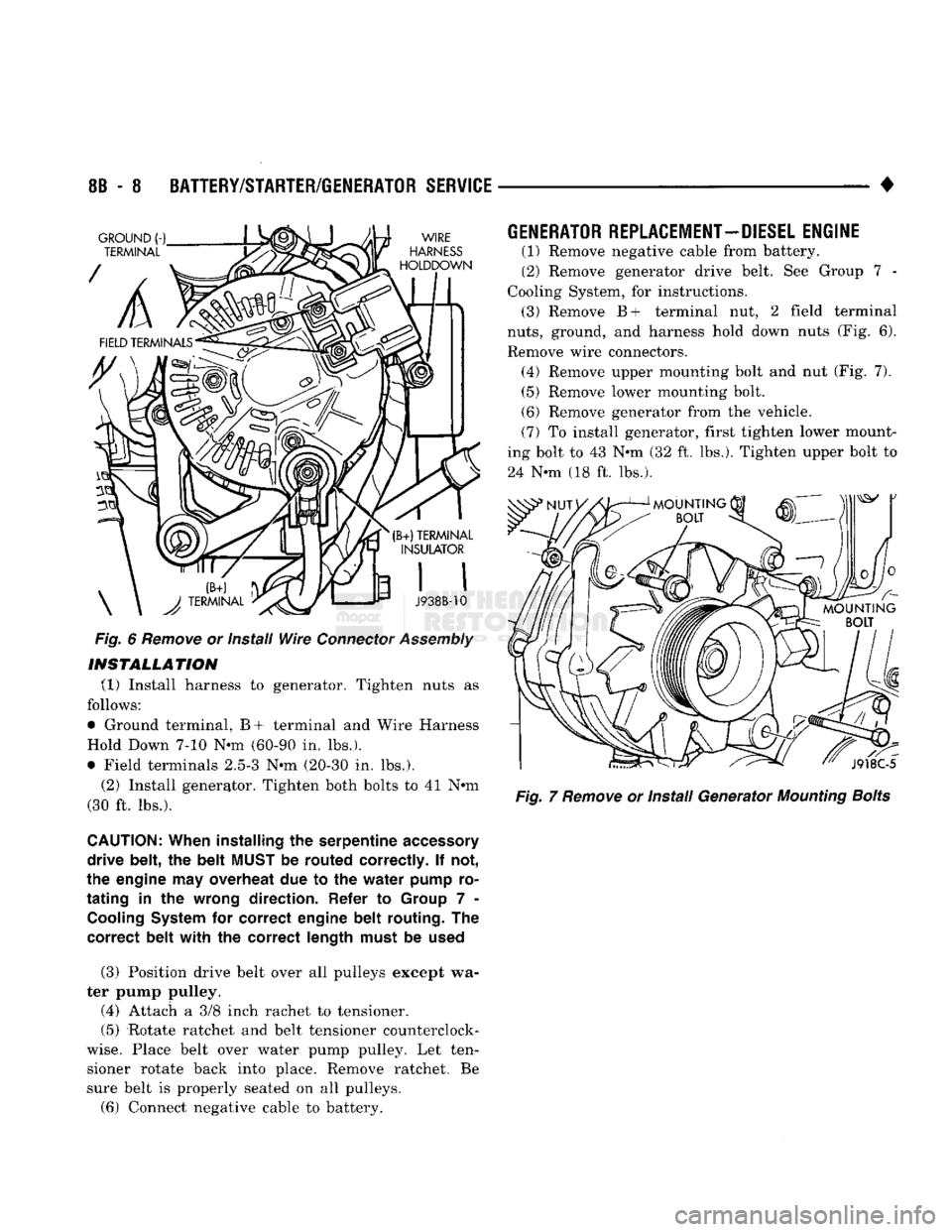
INSTALLATION
(1) Install harness to generator. Tighten nuts as
follows:
• Ground terminal, B+ terminal and Wire Harness
Hold Down 7-10 Nun (60-90 in. lbs.).
• Field terminals 2.5-3 Nun (20-30 in. lbs.).
(2) Install generator. Tighten both bolts to 41 Nun
(30 ft. lbs.).
CAUTION:
When
installing
the
serpentine
accessory
drive
belt,
the
belt
MUST
be
routed
correctly.
If not,
the
engine
may
overheat
due to the
water
pump
ro
tating
in the
wrong
direction.
Refer
to
Group
7 -
Cooling
System
for
correct
engine
belt
routing.
The
correct
belt
with
the
correct
length
must
be
used
(3) Position drive belt over all pulleys except wa
ter pump pulley.
(4) Attach a 3/8 inch rachet to tensioner.
(5) Rotate ratchet and belt tensioner counterclock
wise.
Place belt over water pump pulley. Let ten sioner rotate back into place. Remove ratchet. Be
sure belt is properly seated on all pulleys.
(6) Connect negative cable to battery.
GENERATOR
REPLACEMENT—DIESEL
ENGINE
(1) Remove negative cable from battery.
(2) Remove generator drive belt. See Group 7 -
Cooling System, for instructions. (3) Remove B+ terminal nut, 2 field terminal
nuts,
ground, and harness hold down nuts (Fig. 6).
Remove wire connectors. (4) Remove upper mounting bolt and nut (Fig. 7). (5) Remove lower mounting bolt.
(6) Remove generator from the vehicle.
(7) To install generator, first tighten lower mount
ing bolt to 43 Nun (32 ft. lbs.). Tighten upper bolt to
24 Nun (18 ft. lbs.).
Fig.
7
Remove
or Install Generator
Mounting
Bolts
Page 350 of 1502
•
BATTERY/STARTER/GENERATOR
SERVICE
8B - 9
Load
Test
(Amps)
cold
Cranking
Rating
@ 0°F
Reserve
Capacity
300 Amp 600 Amp 120 Minutes
405 Amp 810 Amp 133 Minutes
535 Amp 1075 Amp
170 Minutes
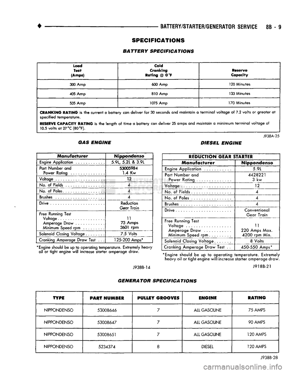
CRANKING
RATING
is the
current
a
battery
can
deliver
for 30
seconds
anej
maintain
a
terminal
voltage
of 7.2
volts
or
greater
at
specified
temperature.
RESERVE
CAPACITY RATING
is the
length
of
time
a
battery
can
deliver
25
amps and maintain
a
minimum
terminal
voltage
of
10.5 volts
at
27 °C (80
°F).
J938A-25
GAS ENGINE DIESEL ENGINE
Manufacturer
Nippondenso
Engine
Application 5.9L, 5.2L
&
3.9L
Part Number and
53005984
Power Rating
1.4
Kw
Voltage
12
No.
of
Fields 4
No.
of
Poles. 4
Brushes
4
Drive Reduction
Gear
Train
Free
Running Test Voltage 11
Amperage Draw 73 Amps
Minimum Speed
rpm
3601
rpm
Solenoid
Closing Voltage 7.5 Volts
Cranking Amperage Draw Test
. . .
125-200
Amps*
*
Engine
should be up to operating
temperature.
Extremely heavy oil
or
tight engine
will
increase
starter
amperage draw.
J938B-14
REDUCTION
GEAR
STARTER
Manufacturer
Nippondenso
Engine
Application 5.9L
Part Number
and
Power Rating
4428221
3
kw
Voltage
12
No.
of
Fields
4
No.
of
Poles 4
Brushes
4
Drive Conventional
Gear Train
Free
Running Test Voltage
Amperage Draw
Minimum Speed
rpm
11
220 Amps Max.
4200
rpm Min.
Solenoid
Closing Voltage 8 Volts
Cranking Amperage Draw Test
. .
450-550
Amps*
*
Engine
should
be up to
operating
temperature.
Extremely heavy oil or tight engine
will
increase
starter
amperage draw.
J918B-21
GENERATOR SPECIFICATIONS
TYPE
PHUT
HUMSIR
PULLEY
GROOVES
ENGINE
RATING
NIPPONDENSO
53008646
7
ALL GASOLINE 75 AMPS
NIPPONDENSO
53008647
7
ALL GASOLINE 90 AMPS
NIPPONDENSO
53008651
7
ALL GASOLINE
120
AMPS
NIPPONDENSO
5234374
8
DIESEL
120 AMPS
J938B-28
SPECIFICATIONS
BATTERY SPECIFICATIONS
Page 367 of 1502
8D
- 16
IGNITION
SYSTEMS
• other operating conditions are causing engine over
heating. (The heat range rating refers to the operat
ing temperature of a particular type spark plug.
Spark plugs are designed to operate within specific
temperature ranges. This depends upon the thickness and length of the center electrodes porcelain insula
tor.)
GROUND
ELECTRODE
CENTER
ELECTRODE
DISSOLVED
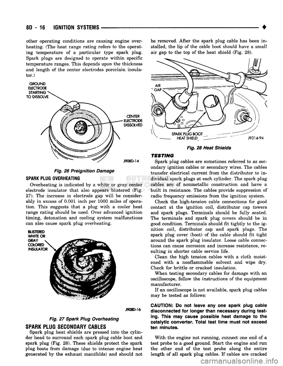
J908D-14 Fig. 26 Preignition Damage
SPARK
PLUG
OVERHEATING
Overheating is indicated by a white or gray center
electrode insulator that also appears blistered (Fig.
27).
The increase in electrode gap will be consider
ably in excess of 0.001 inch per 1000 miles of opera
tion. This suggests that a plug with a cooler heat
range rating should be used. Over advanced ignition
timing, detonation and cooling system malfunctions can also cause spark plug overheating.
BLISTERED
WHITE
OR
J908D-16
Fig. 27 Spark Plug Overheating
SPARK
PLUG
SECONDARY
CABLES
Spark plug heat shields are pressed into the cylin
der head to surround each spark plug cable boot and spark plug (Fig. 28). These shields protect the spark
plug boots from damage (due to intense engine heat
generated by the exhaust manifolds) and should not be removed. After the spark plug cable has been in
stalled, the lip of the cable boot should have a small
air gap to the top of the heat shield (Fig. 28).
Fig.
28 Heat
Shields
TESTING
Spark plug cables are sometimes referred to as sec
ondary ignition cables or secondary wires. The cables
transfer electrical current from the distributor to in dividual spark plugs at each cylinder. The spark plug
cables are of nonmetallic construction and have a
built in resistance. The cables provide suppression of radio frequency emissions from the ignition system.
Check the high-tension cable connections for good
contact at the ignition coil, distributor cap towers and spark plugs. Terminals should be fully seated.
The terminals and spark plug covers should be in good condition. Terminals should fit tightly to the ig
nition coil, distributor cap and spark plugs. The spark plug cover (boot) of the cable should fit tight
around the spark plug insulator. Loose cable connec
tions can cause corrosion and increase resistance, re sulting in shorter cable service life. Clean the high tension cables with a cloth moist
ened with a nonflammable solvent and wipe dry.
Check for brittle or cracked insulation. When testing secondary cables for damage with an
oscilloscope, follow the instructions of the equipment
manufacturer. If an oscilloscope is not available, spark plug cables
may be tested as follows:
CAUTION:
Do not leave any one
spark
plug
cable
disconnected
for
longer
than
necessary
during test
ing.
This
may
cause
possible
heat
damage
to the
catalytic converter. Total test
time
must
not exceed
ten
minutes.
With the engine not running, connect one end of a
test probe to a good ground. Start the engine and run the other end of the test probe along the entire length of all spark plug cables. If cables are cracked
Page 407 of 1502
8F - 4
AUDIO SYSTEMS
• ANTENNA DIAGNOSIS
Turn Ign. Key
to
ACC
Tune
to
Known
Strong AM
Station
f
Check
Antenna Connections
1
1
No
Check
for
Reception Using
A
Test Antenna Repair as
Required*
*Be
Sure
Antenna
is
Properly
Grounded
to
Car.
(Poor
Grounding
of
Antenna
May
Cause
Engine Noise
or
Yes
Static Especially on AM)
Remove
Radio
For
Service
Replace
or
Repair
Defective
Antenna
Or
Lead
in
J928F-4
TIP
OF
MAST
TEST
POINT
RY684
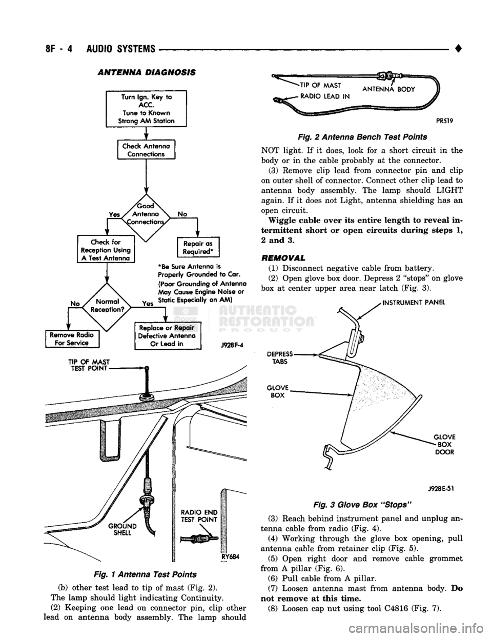
Fig. 1 Antenna Test Points
(b) other test lead to tip of mast (Fig. 2).
The lamp should light indicating Continuity. (2) Keeping one lead on connector pin, clip other
lead on antenna body assembly. The lamp should
-TIP
OF
MAST
•
RADIO LEAD
IN
PR519
Fig.
2 Antenna Bench Test
Points
NOT light. If it does, look for a short circuit in the
body or in the cable probably at the connector.
(3) Remove clip lead from connector pin and clip
on outer shell of connector. Connect other clip lead to
antenna body assembly. The lamp should LIGHT
again. If it does not Light, antenna shielding has an
open circuit.
Wiggle cable over its entire length to reveal in
termittent short or open circuits during steps 1,
2 and 3.
REMOVAL
(1) Disconnect negative cable from battery.
(2) Open glove box door. Depress 2 "stops" on glove
box at center upper area near latch (Fig. 3).
INSTRUMENT
PANEL
DEPRESS
TABS
GLOVE BOX
GLOVE
BOX
DOOR
J928E-51
Fig.
3
Glove
Box
"Stops"
(3) Reach behind instrument panel and unplug an
tenna cable from radio (Fig. 4).
(4) Working through the glove box opening, pull
antenna cable from retainer clip (Fig. 5).
(5) Open right door and remove cable grommet
from A pillar (Fig. 6). (6) Pull cable from A pillar. (7) Loosen antenna mast from antenna body. Do
not remove at this time.
(8) Loosen cap nut using tool C4816 (Fig. 7).
Page 478 of 1502
•
WIRING
DIAGRAMS
8W - 3 fer to a components name in the index if you are
unclear as to what a system may be called.
Diagram pages are arranged starting with the bat
tery and fuses. Then working into charging, starting, and ignition systems. After this they start at the
front of the vehicle and work to rear of the vehicle.
The diagrams end with connector identification
pages.
COMPONENT
IDENTIFICATION
To find a components actual location on the vehicle
refer to the wiring and components section index. This section shows the wire harness routing and the compo
nents location in the vehicle. When using this section
refer to the wiring diagrams for the general location of
the component. Then use the component identification index to locate the proper figure number.
SPLICE
LOCATIONS
Splices are indicated in the wiring diagrams by a
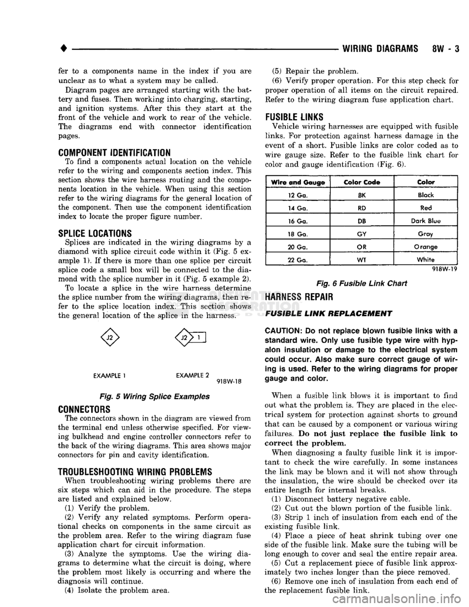
diamond with splice circuit code within it (Fig. 5 ex ample 1). If there is more than one splice per circuit
splice code a small box will be connected to the dia
mond with the splice number in it (Fig. 5 example 2). To locate a splice in the wire harness determine
the splice number from the wiring diagrams, then re
fer to the splice location index. This section shows
the general location of the splice in the harness.
EXAMPLE
1
EXAMPLE
2 918W-18
Fig.
5 Wiring
Splice
Examples
CONNECTORS
The connectors shown in the diagram are viewed from
the terminal end unless otherwise specified. For view ing bulkhead and engine controller connectors refer to
the back of the wiring diagrams. This area shows major connectors for pin and cavity identification.
TROUBLESHOOTING
WIRING
PROBLEMS
When troubleshooting wiring problems there are
six steps which can aid in the procedure. The steps
are listed and explained below. (1) Verify the problem.
(2) Verify any related symptoms. Perform opera
tional checks on components in the same circuit as the problem area. Refer to the wiring diagram fuse
application chart for circuit information. (3) Analyze the symptoms. Use the wiring dia
grams to determine what the circuit is doing, where
the problem most likely is occurring and where the diagnosis will continue. (4) Isolate the problem area. (5) Repair the problem.
(6) Verify proper operation. For this step check for
proper operation of all items on the circuit repaired. Refer to the wiring diagram fuse application chart.
FUSIBLE
LINKS
Vehicle wiring harnesses are equipped with fusible
links.
For protection against harness damage in the
event of a short. Fusible links are color coded as to
wire gauge size. Refer to the fusible link chart for color and gauge identification (Fig. 6).
Wire and
Gauge
Color
Code
Color
12 Ga.
BK
Black
14 Ga.
RD
Red
16 Ga.
DB
Dark
Blue
18 Ga.
GY
Gray
20 Ga.
OR
Orange
22 Ga.
WT
White
918W-19
Fig.
6 Fusible
Link
Chart
HARNESS
REPAIR
FUSIBLE
LINK
REPLACEMENT
CAUTION:
Do not replace blown fusible
links
with
a
standard
wire.
Only
use fusible type
wire
with
hyp-
alon
insulation or
damage
to the electrical
system
could
occur.
Also
make
sure
correct
gauge
of
wir
ing
is
used.
Refer to the wiring
diagrams
for proper
gauge
and
color.
When a fusible link blows it is important to find
out what the problem is. They are placed in the elec
trical system for protection against shorts to ground
that can be caused by a component or various wiring
failures. Do not just replace the fusible link to correct the problem.
When diagnosing a faulty fusible link it is impor
tant to check the wire carefully. In some instances
the link may be blown and it will not show through the insulation, the wire should be checked over its
entire length for internal breaks.
(1) Disconnect battery negative cable.
(2) Cut out the blown portion of the fusible link.
(3) Strip 1 inch of insulation from each end of the
existing fusible link.
(4) Place a piece of heat shrink tubing over one
side of the fusible link. Make sure the tubing will be
long enough to cover and seal the entire repair area.
(5) Cut a replacement piece of fusible link approx
imately two inches longer than the piece removed. (6) Remove one inch of insulation from each end of
the replacement fusible link.
Page 480 of 1502
WIRING DIAGRAMS
SW - 5
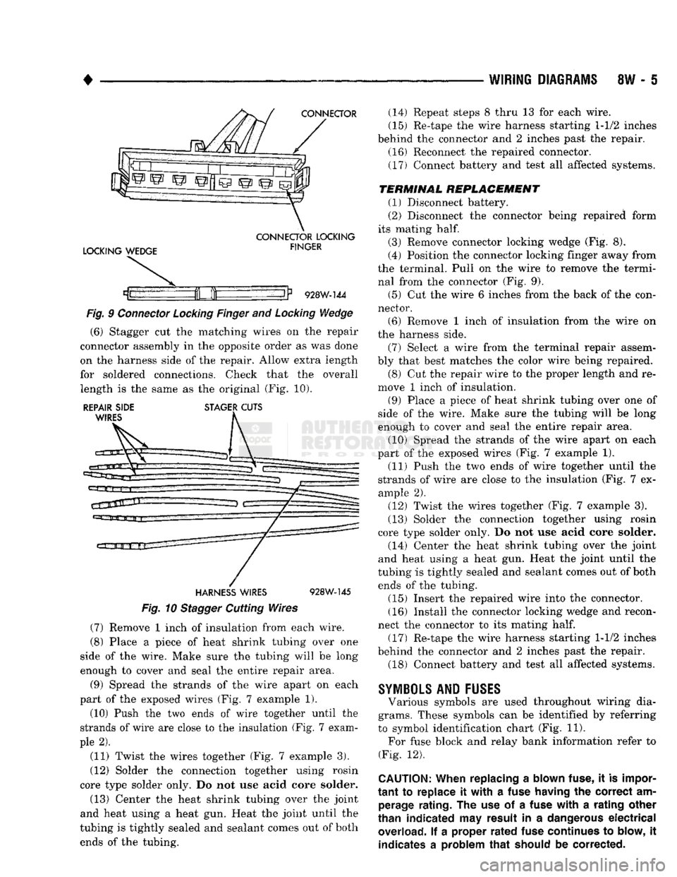
CONNECTOR
LOCKING WEDGE
CONNECTOR
LOCKING
FINGER
If
928W-144
Fig.
9
Connector
Locking
Finger
and
Locking
Wedge
(6) Stagger cut the matching wires on the repair
connector assembly in the opposite order as was done
on the harness side of the repair. Allow extra length
for soldered connections. Check that the overall length is the same as the original (Fig. 10).
REPAIR SIDE STAGER CUTS WIRES
HARNESS
WIRES
928W-145
Fig.
10
Stagger
Cutting Wires (7) Remove 1 inch of insulation from each wire.
(8) Place a piece of heat shrink tubing over one
side of the wire. Make sure the tubing will be long
enough to cover and seal the entire repair area.
(9) Spread the strands of the wire apart on each
part of the exposed wires (Fig. 7 example 1).
(10) Push the two ends of wire together until the
strands of wire are close to the insulation (Fig. 7 exam
ple 2).
(11) Twist the wires together (Fig. 7 example 3).
(12) Solder the connection together using rosin
core type solder only. Do not use acid core solder.
(13) Center the heat shrink tubing over the joint
and heat using a heat gun. Heat the joint until the
tubing is tightly sealed and sealant comes out of both ends of the tubing. (14) Repeat steps 8 thru 13 for each wire.
(15) Re-tape the wire harness starting 1-1/2 inches
behind the connector and 2 inches past the repair. (16) Reconnect the repaired connector.
(17) Connect battery and test all affected systems.
TERMINAL
REPLACEMENT
(1) Disconnect battery.
(2) Disconnect the connector being repaired form
its mating
half.
(3) Remove connector locking wedge (Fig. 8).
(4) Position the connector locking finger away from
the terminal. Pull on the wire to remove the termi nal from the connector (Fig. 9).
(5) Cut the wire 6 inches from the back of the con
nector. (6) Remove 1 inch of insulation from the wire on
the harness side.
(7) Select a wire from the terminal repair assem
bly that best matches the color wire being repaired. (8) Cut the repair wire to the proper length and re
move 1 inch of insulation.
(9) Place a piece of heat shrink tubing over one of
side of the wire. Make sure the tubing will be long
enough to cover and seal the entire repair area.
(10) Spread the strands of the wire apart on each
part of the exposed wires (Fig. 7 example 1). (11) Push the two ends of wire together until the
strands of wire are close to the insulation (Fig. 7 ex
ample 2).
(12) Twist the wires together (Fig. 7 example 3).
(13) Solder the connection together using rosin
core type solder only. Do not use acid core solder.
(14) Center the heat shrink tubing over the joint
and heat using a heat gun. Heat the joint until the
tubing is tightly sealed and sealant comes out of both ends of the tubing.
(15) Insert the repaired wire into the connector.
(16) Install the connector locking wedge and recon
nect the connector to its mating
half.
(17) Re-tape the wire harness starting 1-1/2 inches
behind the connector and 2 inches past the repair. (18) Connect battery and test all affected systems.
SYMBOLS
AND
FUSES
Various symbols are used throughout wiring dia
grams. These symbols can be identified by referring
to symbol identification chart (Fig. 11). For fuse block and relay bank information refer to
(Fig. 12).
CAUTION:
When replacing
a
blown fuse,
it is
impor
tant
to
replace
it
with
a
fuse having
the
correct
am
perage rating.
The use of a
fuse
with
a
rating other
than indicated
may
result
in a
dangerous
electrical
overload.
If a
proper
rated
fuse continues
to
blow,
it
indicates
a
problem
that
should
be
corrected.