1993 DODGE TRUCK length
[x] Cancel search: lengthPage 735 of 1502
9
- 130 5.9L
(DIESEL) ENGINE
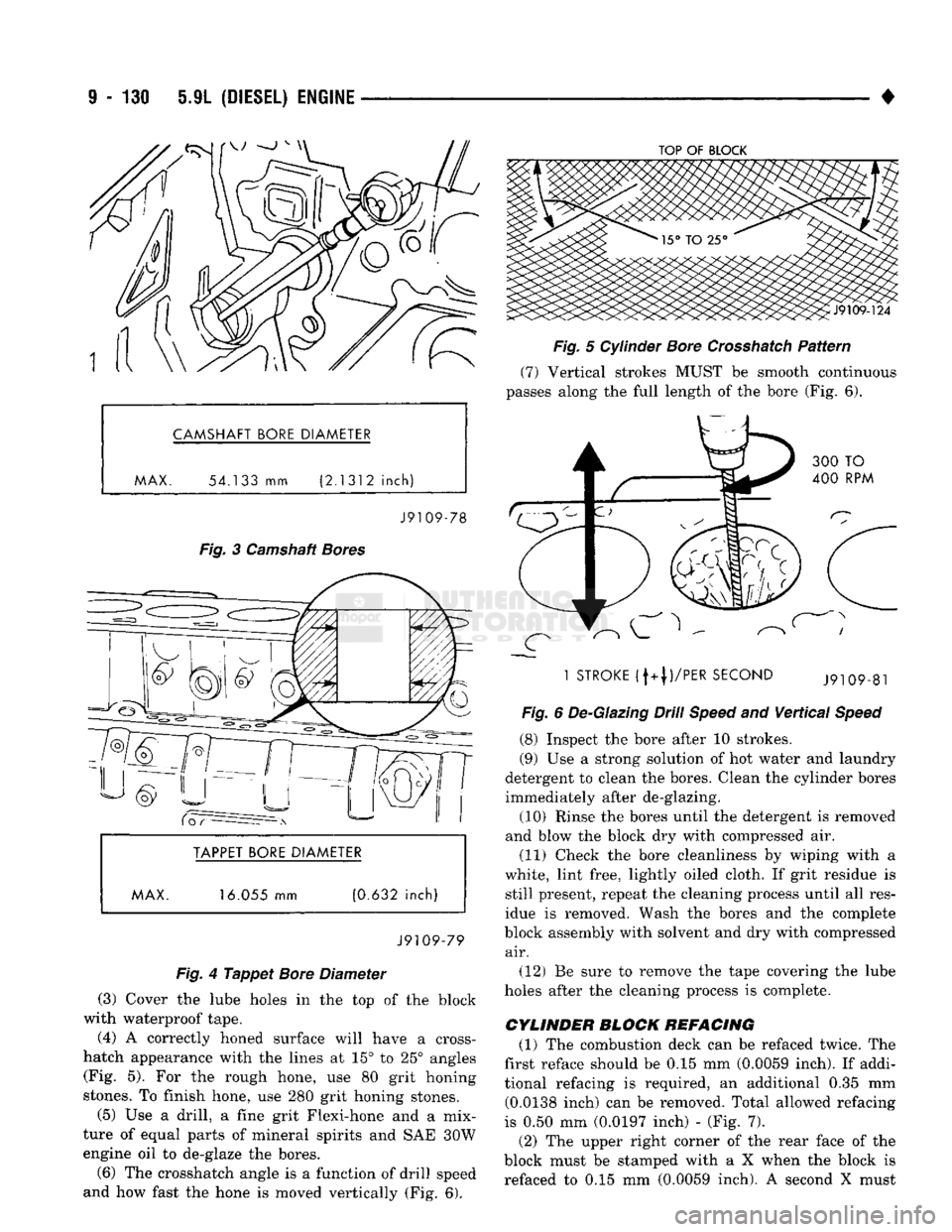
• CAMSHAFT BORE DIAMETER
MAX.
54.133
mm
(2.1312
inch)
J9109-78
Fig.
3 Camshaft
Bores
BORE DIAMETER
MAX. 16.055 mm (0.632 inch)
J9109-79
Fig.
4
Tappet
Bore
Diameter
(3) Cover the lube holes in the top of the block
with waterproof tape.
(4) A correctly honed surface will have a cross-
hatch appearance with the lines at 15° to 25° angles (Fig. 5). For the rough hone, use 80 grit honing
stones. To finish hone, use 280 grit honing stones.
(5) Use a drill, a fine grit Flexi-hone and a mix
ture of equal parts of mineral spirits and SAE 30W engine oil to de-glaze the bores.
(6) The Crosshatch angle is a function of drill speed
and how fast the hone is moved vertically (Fig. 6).
TOP
OF
BLOCK
Fig.
5 Cylinder
Bore
Crosshatch
Pattern
(7) Vertical strokes MUST be smooth continuous
passes along the full length of the bore (Fig. 6).
1
STROKE
(f+|)/PER
SECOND
Fig.
6 De-Glazing Drill
Speed
and
Vertical
Speed
(8) Inspect the bore after 10 strokes.
(9) Use a strong solution of hot water and laundry
detergent to clean the bores. Clean the cylinder bores
immediately after de-glazing.
(10) Rinse the bores until the detergent is removed
and blow the block dry with compressed air. (11) Check the bore cleanliness by wiping with a
white, lint free, lightly oiled cloth. If grit residue is still present, repeat the cleaning process until all res
idue is removed. Wash the bores and the complete
block assembly with solvent and dry with compressed air.
(12) Be sure to remove the tape covering the lube
holes after the cleaning process is complete.
CYLINDER BLOCK REFACING
(1) The combustion deck can be refaced twice. The
first reface should be 0.15 mm (0.0059 inch). If addi
tional refacing is required, an additional 0.35 mm (0.0138 inch) can be removed. Total allowed refacing
is 0.50 mm (0.0197 inch) - (Fig. 7).
(2) The upper right corner of the rear face of the
block must be stamped with a X when the block is refaced to 0.15 mm (0.0059 inch). A second X must
Page 754 of 1502
• 5.9L
(DIESEL) ENGINE
9 - 151
SPECIFICATIONS—5.9L DIESEL ENGINES
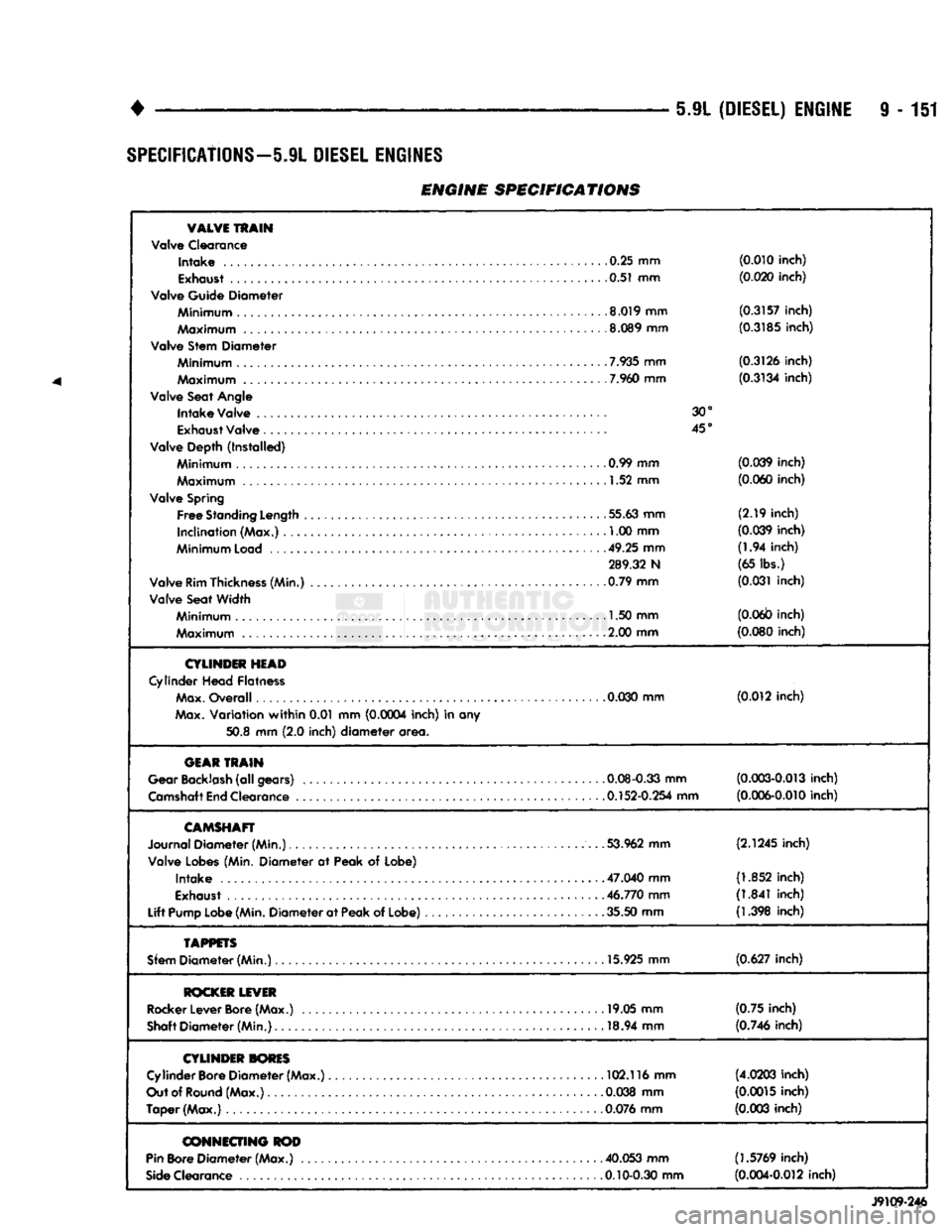
ENGINE SPECIFICATIONS
VALVE
TRAIN
Valve Clearance
Intake
.0.25 mm
(0.010 inch)
0.51 mm (0.020 inch)
Valve Guide Diameter
Minimum
8.019 mm
(0.3157 inch)
Maximum
.8.089 mm
(0.3185 inch)
Valve Stem Diameter
7.935
mm (0.3126 inch)
Maximum
7.960
mm
(0.3134 inch)
Valve Seat
Angle
Intake
Valve 30°
Exhaust
Valve 45°
Valve Depth (Installed)
Minimum
. .......... 0.99 mm (0.039 inch)
Maximum
1.52 mm
(0.060 inch)
Valve
Spring
Free
Standing
Length
55.63 mm
(2.19
inch)
Inclination (Max.) , 1.00 mm
(0.039 inch)
Minimum
Load
49.25 mm
(1.94
inch)
289.32 N (65 lbs.)
Valve
Rim
Thickness
(Min.) 0.79 mm
(0.031 inch)
Valve Seat Width
Minimum
1.50 mm
(0.06b inch)
Maximum
. 2.00 mm
(0.080 inch)
CYLINDER
HEAD
Cylinder
Head Flatness
Max.
Overall
0.030
mm (0.012 inch)
Max.
Variation
within
0.01 mm (0.0004 inch) in any
50.8
mm
(2.0
inch)
diameter
area.
GEAR
TRAIN
Gear
Backlash
(all gears) 0.08-0.33 mm
(0.003-0.013 inch)
Camshaft
End
Clearance 0.152-0.254 mm
(0.006-0.010 inch)
CAMSHAFT
Journal Diameter (Min.) 53.962 mm
(2.1245 inch)
Valve
Lobes
(Min. Diameter at Peak of Lobe)
Intake
.... 47.040 mm
(1.852 inch)
Exhaust
46.770 mm
(1.841 inch)
Lift
Pump
Lobe
(Min.
Diameter at
Peak
of Lobe) 35.50 mm
(1.398 inch)
TAPPETS
Sfem
Diameter (Min.) 15.925 mm
(0.627 inch)
ROCKER
LEVER
Rocker
Lever
Bore
(Max.) 19.05 mm
(0.75
inch)
Shaft
Diameter (Min.) 18.94 mm
(0.746 inch)
CYLINDER
TORES
Cylinder
Bore
Diameter (Max.) 102.116 mm
(4.0203 inch)
Out
of
Round
(Max.) . .0.038 mm
(0.0015 inch)
Taper (Max.)
0.076
mm
(0.003 inch)
CONNECTING
ROD
Pin
Bore
Diameter (Max.) . 40.053 mm (1.5769 inch)
Side
Clearance 0.10-0.30 mm
(0.004-0.012 inch)
J9109-246
Page 772 of 1502
•
EXHAUST SYSTEM
AND
INTAKE MANIFOLD
11-13
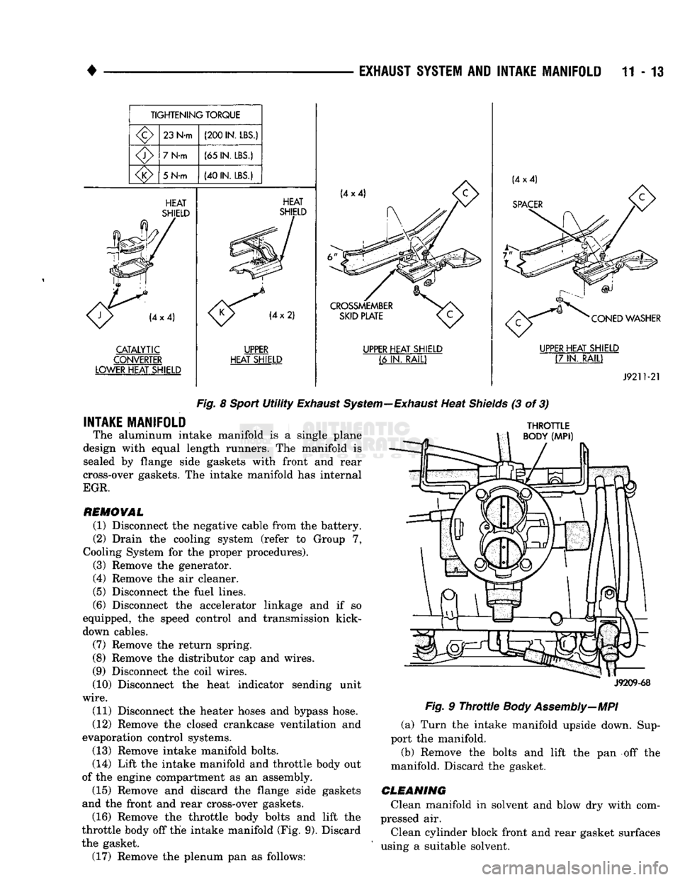
TIGHTENING
TORQUE
23
N-m
(200
IN. LBS.)
7
N-m
(65
IN. LBS.)
5 N-m
(40
IN. LBS.)
HEAT
SHIELD CATALYTIC
CONVERTER
LOWER HEAT SHIELD HEAT
SHIELD UPPER
HEAT
SHIELD
CROSSMEMBER
SKID
PLATE
UPPER HEAT SHIELD
(6 IN.
RAIL) CONED WASHER
UPPER HEAT SHIELD
(7 IN.
RAIL)
J9211-21
Fig.
8
Sport
Utility
Exhaust
System—Exhaust
Heat
Shields
(3 of 3)
INTAKE MANIFOLD
The aluminum intake manifold is a single plane
design with equal length runners. The manifold is sealed by flange side gaskets with front and rear
cross-over gaskets. The intake manifold has internal
EGR.
REMOVAL
(1) Disconnect the negative cable from the battery.
(2) Drain the cooling system (refer to Group 7,
Cooling System for the proper procedures).
(3) Remove the generator.
(4) Remove the air cleaner.
(5) Disconnect the fuel lines.
(6) Disconnect the accelerator linkage and if so
equipped, the speed control and transmission kick-
down cables.
(7) Remove the return spring.
(8) Remove the distributor cap and wires.
(9) Disconnect the coil wires.
(10) Disconnect the heat indicator sending unit
wire.
(11) Disconnect the heater hoses and bypass hose.
(12) Remove the closed crankcase ventilation and
evaporation control systems. (13) Remove intake manifold bolts.
(14) Lift the intake manifold and throttle body out
of the engine compartment as an assembly. (15) Remove and discard the flange side gaskets
and the front and rear cross-over gaskets.
(16) Remove the throttle body bolts and lift the
throttle body off the intake manifold (Fig. 9). Discard
the gasket. (17) Remove the plenum pan as follows:
THROTTLE
BODY
(MPI)
J9209-68
Fig.
9
Throttle
Body Assembly—MPI
(a) Turn the intake manifold upside down. Sup
port the manifold.
(b) Remove the bolts and lift the pan off the
manifold. Discard the gasket.
CLEANING
Clean manifold in solvent and blow dry with com
pressed air.
Clean cylinder block front and rear gasket surfaces
using a suitable solvent.
Page 812 of 1502
FRAME
AND
BUMPERS
13 - 25
FUNCTION
The frame is the foundation and the structural cen
ter of the vehicle. The primary function of a frame is
to provide support and attachment locations: • For all the chassis/drivetrain components
• For the cab/body
• For the vehicle payload While limiting deflections and twisting of the
frame members. The frame maintains the correct relationship and
alignment of the powertrain. This relationship and
alignment ensures normal operation of the attached
units.
CONSTRUCTION MATERIAL High-strength, carbon steel with a minimum yield
strength of 32,000 psi is used to construct frame side
rails.
A frame made of 32,000 psi minimum yield
strength steel has, in reality, a range of 32,000 to
44,000 psi yield strength.
For 4WD vehicle applications, the frame side rails
reinforcements are constructed of the same high- strength, carbon steel as the side rails.
BENDING RESISTANCE A frame reacts to its load and the road surface de
viations by deflecting and twisting. The primary de
flecting frame members are the side rails. Resistance
to frame twist is provided by the crossmembers.
FRAME
INSPECTION/MEASUREMENTS
INSPECTION Inspect the frame members for visible damage and
metal deformations. Inspect all riveted, bolted and
welded connections for looseness and/or missing hardware. All damaged areas must be repaired and/or the
frame members replaced, as necessary.
MEASUREMENTS Measure the frame for mis-alignment with the cab/
body and cargo box attached to the frame. Figures 7, 8, 9 provide the frame alignment reference dimen
sions.
The following information applies to all measure
ments.
(1) Place the vehicle on a level surface.
(2) If the vehicle is loaded, verify the vehicle does
not exceed the gross vehicle weight rating (GVWR).
Verify the load is distributed in the vehicle as evenly as possible. For better measurement results, remove
the cargo/payload from the vehicle.
(3) Measure the tire inflation pressures. Adjust as
necessary.
HORIZONTAL/DIAGONAL
FRAME MEASUREMENTS
Determine the frame horizontal, according to the
following procedure.
(1) Select several reference points along one frame
side rail, preferably at the crossmember junctions.
(2) Transfer these reference points to the surface/
floor. Paper sheets can be attached to the surface be low the reference points.
(3) Locate the same reference points on the other
frame side rail. Transfer them to the surface/floor.
(4) Move the vehicle away. Measure between all
the reference points diagonally from and parallel to
the side rails (Fig. 10). The corresponding measure ments should not differ by more than 6 mm (1/4 in).
(5)
Measure the distance between the two front
reference points. Measure the distance between the
two rear reference points. Divide each distance in
half and indicate the two half-way points on the sur
face/floor. Designate the front point as 1 and the rear
point as 2 (Fig. 10).
(6) Place a chalk-line between points 1 and 2 (Fig.
10) and snap the string.
(7) Determine how close the center line is to the
diagonal intersection points in Figure 10.
(8) The marks on the floor will show the amount of
frame misalignment.
(9) The reference point transferred from one side
rail should be within 3 mm (1/8 in) of the opposite
reference point.
(10) Frame bow to the side should not exceed 3
mm per 2540 mm (1/8 inch per 100 inches) in frame
length.
(11) The overall width of the frame should not
vary more than 3 mm (1/8 in). (12) Repeat steps (1) through (11) after straighten
ing the frame.
Refer to Figures 7, 8, and 9 for frame horizon
tal alignment reference dimensions.
TWIST
AND PARALLEL FRAME MEASUREMENTS
Determine the amount of frame twist using the fol
lowing procedure.
(1) Mark the vertical reference points under the
frame side rails at 305-mm (12-in) intervals. Start at
the rear frame crossmember.
(2) Measure the distance up from a level surface/
floor to each corresponding reference point. (3) The distance to a reference point under one
side rail should be a maximum of 3 mm (1/8 in)
dif
ference than the opposite side rail.
Refer to Figures 7, 8 and 9 for frame vertical
alignment reference dimensions.
Page 818 of 1502
1
•
FRAME
AND
BUMPERS
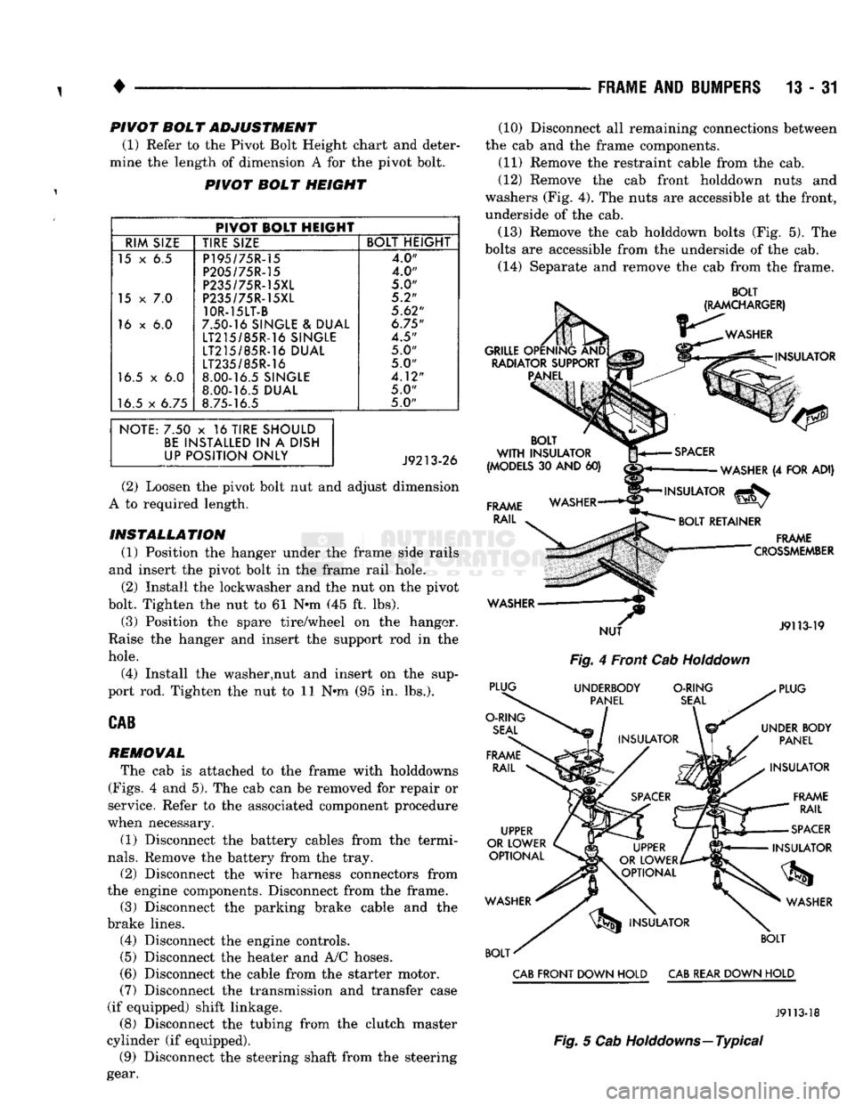
13 - 31 PIVOT BOL T ADJUSTMENT
(1) Refer to the Pivot Bolt Height chart and deter
mine the length of dimension A for the pivot bolt.
PIVOT BOLT HEIGHT
PIVOT BOLT HEIGHT
RIM SIZE TIRE SIZE BOLT HEIGHT
15 x 6.5 P195/75R-15
4.0"
P205/75R-15 4.0"
P235/75R-15XL
5.0"
15
x 7.0
P235/75R-15XL 5.2"
10R-15LT-B
5.62"
16 x 6.0 7.50-16 SINGLE & DUAL
6.75"
LT215/85R-16 SINGLE
4.5"
LT215/85R-16 DUAL 5.0"
LT235/85R-16
5.0"
16.5 x 6.0 8.00-16.5 SINGLE
4.12"
8.00-16.5 DUAL
5.0"
16.5 x 6.75 8.75-16.5 5.0"
NOTE: 7.50 x 16 TIRE SHOULD BE INSTALLED IN A DISH
UP POSITION ONLY
(2) Loosen the pivot bolt nut and adjust dimension
A to required length.
INSTALLATION (1) Position the hanger under the frame side rails
and insert the pivot bolt in the frame rail hole. (2) Install the lockwasher and the nut on the pivot
bolt. Tighten the nut to 61 N*m (45 ft. lbs).
(3) Position the spare tire/wheel on the hanger.
Raise the hanger and insert the support rod in the
hole.
(4) Install the washer,nut and insert on the sup
port rod. Tighten the nut to 11 Nnn (95 in. lbs.).
CAB
REMOVAL
The cab is attached to the frame with holddowns
(Figs.
4 and 5). The cab can be removed for repair or
service. Refer to the associated component procedure
when necessary.
(1) Disconnect the battery cables from the termi
nals.
Remove the battery from the tray.
(2) Disconnect the wire harness connectors from
the engine components. Disconnect from the frame. (3) Disconnect the parking brake cable and the
brake lines. (4) Disconnect the engine controls.
(5)
Disconnect the heater and A/C hoses.
(6) Disconnect the cable from the starter motor.
(7)
Disconnect the transmission and transfer case
(if equipped) shift linkage. (8) Disconnect the tubing from the clutch master
cylinder (if equipped). (9) Disconnect the steering shaft from the steering
gear. (10) Disconnect all remaining connections between
the cab and the frame components. (11) Remove the restraint cable from the cab.
(12) Remove the cab front holddown nuts and
washers (Fig. 4). The nuts are accessible at the front,
underside of the cab.
(13) Remove the cab holddown bolts (Fig. 5). The
bolts are accessible from the underside of the cab.
(14) Separate and remove the cab from the frame.
BOLT
Fig.
4 Front Cab
Holddown
CAB
FRONT DOWN HOLD
CAB
REAR DOWN HOLD
J9113-18
Fig.
5 Cab Holddowns—Typical
Page 848 of 1502
•
FUEL
SYSTEM
14-29
MULTI-PORT
FUEL
INJECTION
(MPI)-COMPONENT DESCRIPTION/SYSTEM
OPERATION-EXCEPT DIESEL
INDEX
page
Air
Conditioning (A/C) Clutch
Relay-Pern
Output
. 35
Air
Conditioning (A/C)
Controls—PCM
Input
.... 31
Auto
Shut
Down
(ASD)
Relay-PCM
Output
. ... 36
Automatic
Shut
Down
(ASD)
Sense-PCM
Input
. 31
Battery
Voltage-PCM
Input
32
Brake
Switch-PCM
Input
32
Camshaft
Position
Sensor—PCM
Input
32
Charge
Air
Temperature
Sensor—PCM
Input
. . . 32
Crankshaft
Position
Sensor-PCM
Input
.......
32
Electric
Exhaust
Gas Recirculation Transducer
(EET)
Solenoid-PCM
Output
...
.......
36
Engine
Coolant Temperature
Sensor—PCM
Input
. 33
EVAP
Canister
Purge
Solenoid—PCM
Output
. . . 37
Fuel
Injectors-PCM Output
37
Fuel
Pressure
Regulator
41
Fuel
Rail
41
General
Information
.......................
29
Generator
Field-PCM
Output
36
Generator
Lamp-PCM
Output
36
Idle
Air
Control
(IAC)
Motor-PCM
Output
......
36
Ignition
Circuit
Sense—PCM
Input
33
GENERAL
INFORMATION
All
gas
powered engines
are
equipped with sequen
tial Multi-Port Fuel Injection (MPI).
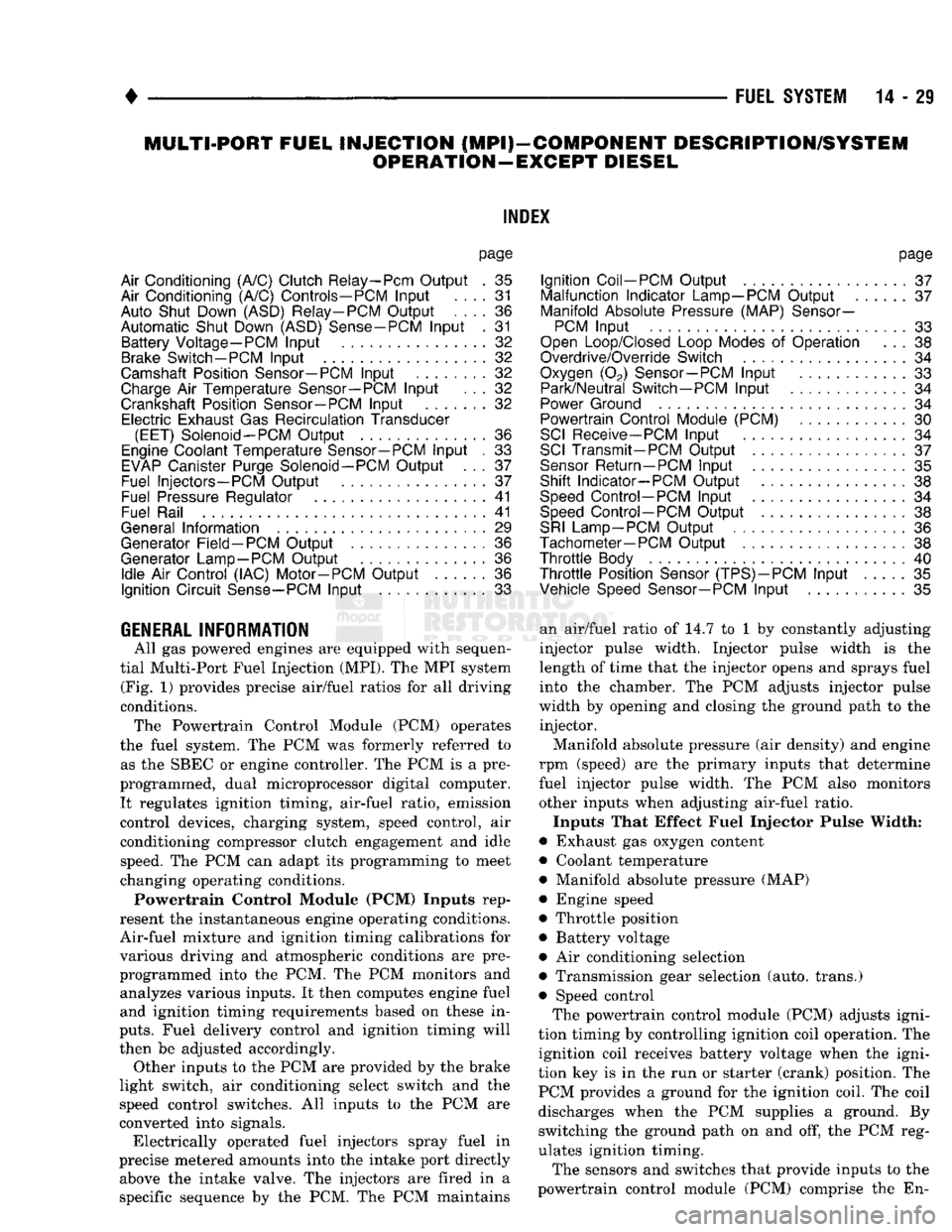
The MPI
system (Fig.
1)
provides precise air/fuel ratios
for all
driving
conditions. The Powertrain Control Module
(PCM)
operates
the fuel system.
The PCM was
formerly referred
to
as
the
SBEC
or
engine controller.
The PCM is a
pre
programmed, dual microprocessor digital computer. It regulates ignition timing, air-fuel ratio, emission
control devices, charging system, speed control,
air
conditioning compressor clutch engagement
and
idle speed.
The PCM can
adapt
its
programming
to
meet
changing operating conditions.
Powertrain Control Module (PCM) Inputs rep
resent
the
instantaneous engine operating conditions.
Air-fuel mixture
and
ignition timing calibrations
for
various driving
and
atmospheric conditions
are
pre
programmed into
the PCM. The PCM
monitors
and
analyzes various inputs.
It
then computes engine fuel
and ignition timing requirements based
on
these
in
puts.
Fuel delivery control
and
ignition timing will
then
be
adjusted accordingly. Other inputs
to the
PCM
are
provided
by the
brake
light switch,
air
conditioning select switch
and the
speed control switches.
All
inputs
to the PCM are
converted into signals. Electrically operated fuel injectors spray fuel
in
precise metered amounts into
the
intake port directly above
the
intake valve.
The
injectors
are
fired
in a
specific sequence
by the PCM. The PCM
maintains
page
Ignition
Coil-PCM
Output
37
Malfunction Indicator
Lamp—PCM
Output
37
Manifold
Absolute
Pressure
(MAP)
Sensor-
PCM
Input
33
Open
Loop/Closed
Loop
Modes
of
Operation
. . . 38
Overdrive/Override
Switch
34
Oxygen
(02)
Sensor—PCM
Input
33
Park/Neutral
Switch—PCM
Input
34
Power
Ground
34
Powertrain Control Module
(PCM)
30
SCI
Receive-PCM
Input
. 34
SCI
Transmit-PCM
Output
37
Sensor
Return
—PCM
Input
35
Shift Indicator-PCM Output
38
Speed
Control-PCM
Input
34
Speed
Control-PCM
Output
38
SRI
Lamp-PCM
Output
36
Tachometer—PCM
Output
38
Throttle
Body
40
Throttle
Position
Sensor
(TPS)-PCM
Input
35
Vehicle
Speed
Sensor-PCM
Input
35
an air/fuel ratio
of 14.7 to 1 by
constantly adjusting
injector pulse width. Injector pulse width
is the
length
of
time that
the
injector opens
and
sprays fuel into
the
chamber.
The PCM
adjusts injector pulse
width
by
opening
and
closing
the
ground path
to the
injector.
Manifold absolute pressure
(air
density)
and
engine
rpm (speed)
are the
primary inputs that determine
fuel injector pulse width.
The PCM
also monitors
other inputs when adjusting air-fuel ratio.
Inputs That Effect Fuel Injector Pulse Width:
• Exhaust
gas
oxygen content
• Coolant temperature
• Manifold absolute pressure (MAP)
• Engine speed
• Throttle position
• Battery voltage •
Air
conditioning selection
• Transmission gear selection (auto, trans.)
• Speed control The powertrain control module (PCM) adjusts igni
tion timing
by
controlling ignition coil operation.
The
ignition coil receives battery voltage when
the
igni
tion
key is in the run or
starter (crank) position.
The
PCM provides
a
ground
for the
ignition coil.
The
coil
discharges when
the PCM
supplies
a
ground.
By
switching
the
ground path
on and off, the PCM
reg
ulates ignition timing.
The sensors
and
switches that provide inputs
to the
powertrain control module
(PCM)
comprise
the En-
Page 904 of 1502
•
FUEL SYSTEM
14-85 to pass through it, but prevents moisture (water)
from doing so. Moisture collects at the bottom of the
separator filter.
WARNING:
EXTINGUISH
ALL
SMOKING
MATERI
ALS
BEFORE
DRAINING
THE
FUEL/WATER
SEPA
RATOR
FILTER.
There is a drain at the bottom of the separator fil
ter (Fig. 16). Place a drain pan under the drain tube.
With the engine not running, push up on the drain
to remove the water from the separator filter. Hold
the drain open until all water and contaminants
have been removed and clean fuel exits the drain. Dispose of mixture in drain pan according to applica
ble regulations.
Refer to the maintenance schedules in Group 0 in
this manual for the recommended fuel/water separa
tor filter replacement intervals.
KSB
SOLENOID
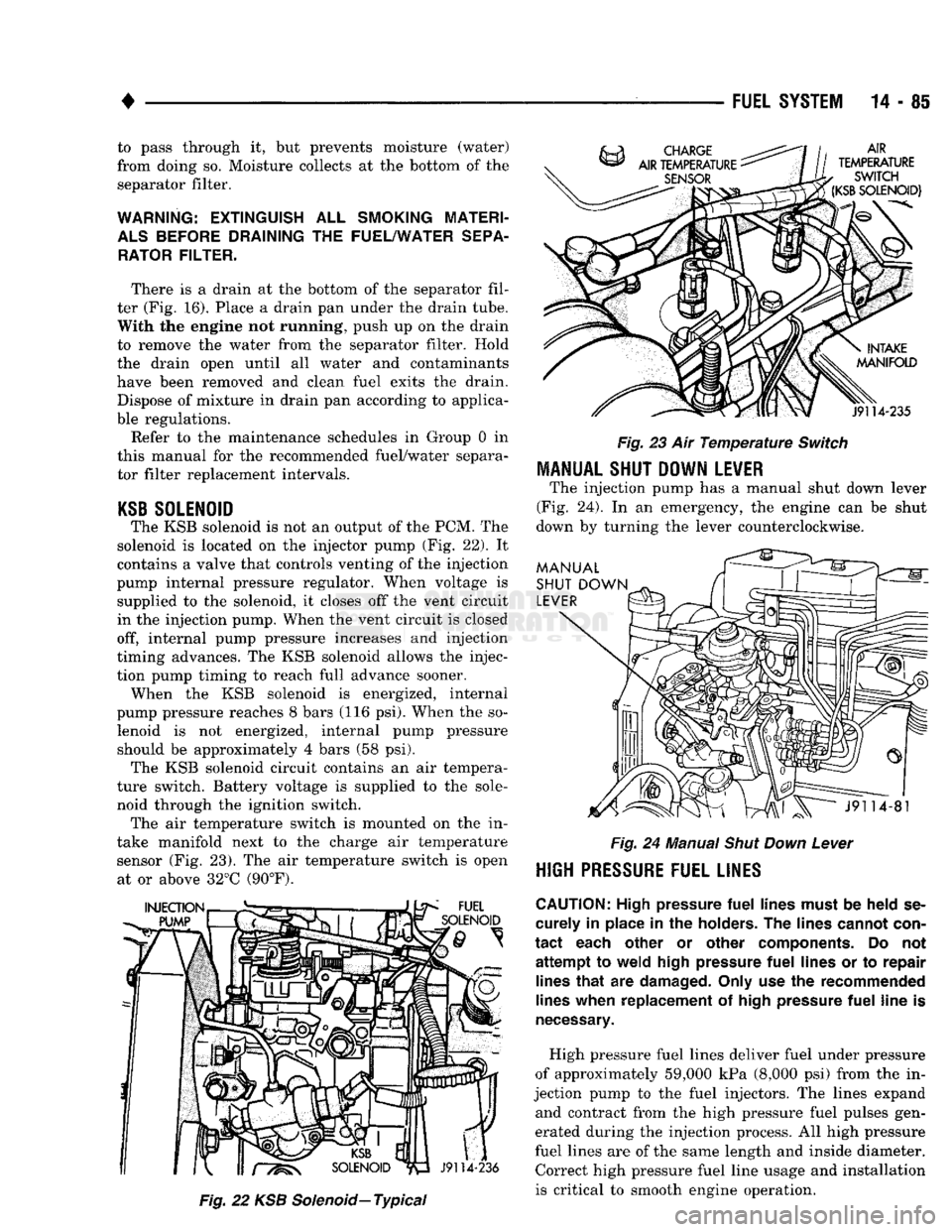
The KSB solenoid is not an output of the PCM. The
solenoid is located on the injector pump (Fig. 22). It
contains a valve that controls venting of the injection
pump internal pressure regulator. When voltage is supplied to the solenoid, it closes off the vent circuit
in the injection pump. When the vent circuit is closed
off, internal pump pressure increases and injection
timing advances. The KSB solenoid allows the injec
tion pump timing to reach full advance sooner. When the KSB solenoid is energized, internal
pump pressure reaches 8 bars (116 psi). When the so lenoid is not energized, internal pump pressure should be approximately 4 bars (58 psi). The KSB solenoid circuit contains an air tempera
ture switch. Battery voltage is supplied to the sole
noid through the ignition switch. The air temperature switch is mounted on the in
take manifold next to the charge air temperature sensor (Fig. 23). The air temperature switch is open at or above 32°C (90°F).
Fig.
22 KSB
Solenoid—
Typical
Fig.
23 Air
Temperature
Switch
MANUAL SHUT DOWN LEVER
The injection pump has a manual shut down lever
(Fig. 24). In an emergency, the engine can be shut
down by turning the lever counterclockwise.
Fig.
24 Manual
Shut
Down
Lever
HIGH
PRESSURE FUEL LINES
CAUTION:
High pressure
fuel
lines must
be
held
se
curely
in
place
in the
holders.
The
lines cannot con
tact
each other
or
other components.
Do not
attempt
to
weld high pressure
fuel
lines
or to
repair lines
that
are
damaged. Only use
the
recommended
lines when replacement
of
high pressure
fuel
line
is
necessary.
High pressure fuel lines deliver fuel under pressure
of approximately 59,000 kPa (8,000 psi) from the in
jection pump to the fuel injectors. The lines expand and contract from the high pressure fuel pulses gen
erated during the injection process. All high pressure
fuel lines are of the same length and inside diameter. Correct high pressure fuel line usage and installation
is critical to smooth engine operation.
Page 933 of 1502
14 - 114
FUEL
SYSTEM
• (15) Install fuel injection pump supply line. Refer
to Fuel Injection Pump Supply Line.
(16) Connect electrical connector to fuel solenoid.
(17) Connect electrical connector to KSB solenoid.
(18) Install fuel pump vent line and capscrew.
(19) Install air fuel control tube.
(20) Install throttle bracket (Fig. 15). Tighten
mounting bolts to 24 N»m (18 ft. lbs.) torque.
(21) Install throttle linkage. When connecting the
cable to the control lever, adjust the length so the le
ver has stop-to-stop movement. Refer to Accelerator
Pedal and Throttle Controls section of Group 14,
Fuel Systems.
(22) Install and adjust throttle position sensor. Re
fer to Service Adjustments.
(23) Bleed air from fuel system. Refer to High
Pressure Fuel Lines in the Air Bleeding portion of
the Diesel Fuel Injection section of Group 14, Fuel Systems. (24) Adjust the low idle speed if required. Refer to
Service Adjustments near the end of this group. (25) Inspect throttle linkage to be sure that the
control lever breaks over the full throttle position.
Adjust as necessary. Refer to Accelerator Pedal and
Throttle Cable section of Group 14, Fuel Systems.
FUEL
INJECTION
PUMP
SUPPLY
LINE
REMOVAL
(1) Disconnect negative cable from battery.
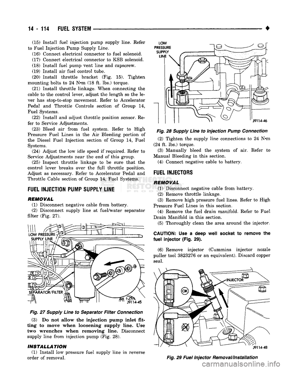
(2) Disconnect supply line at fuel/water separator
filter (Fig. 27).
Fig.
27
Supply
Line
to Separator
Filter
Connection
(3) Do not allow the injection pump inlet fit
ting to move when loosening supply line. Use two wrenches when removing line. Disconnect
supply line from injection pump (Fig. 28).
INSTALLATION
(1) Install low pressure fuel supply line in reverse
order of removal.
Fig.
28
Supply
Line
to Injection
Pump
Connection
(2) Tighten the supply line connections to 24 Nnn
(24 ft. lbs.) torque.
(3) Manually bleed the system of air. Refer to
Manual Bleeding in this section.
(4) Connect negative cable to battery.
FUEL
INJECTORS
REMOVAL
(1) Disconnect negative cable from battery.
(2) Remove throttle linkage.
(3) Remove high pressure fuel lines. Refer to High
Pressure Fuel Lines in this section. (4) Remove the fuel drain manifold. Refer to Fuel
Drain Manifold in this section. (5) Thoroughly clean the area around the injector.
CAUTION:
Use a deep
well
socket
to remove the
fuel
injector (Fig. 29).
(6) Remove injector (Cummins injector nozzle
puller tool 3823276 or an equivalent). Discard copper seal.
Fig.
29
Fuel
Injector Removal/Installation