1993 DODGE TRUCK length
[x] Cancel search: lengthPage 935 of 1502
14
• 116
FUEL
SYSTEM
Fig.
34 WIF
Sensor,
Drain
Valve
Assembly
INSTALLATION
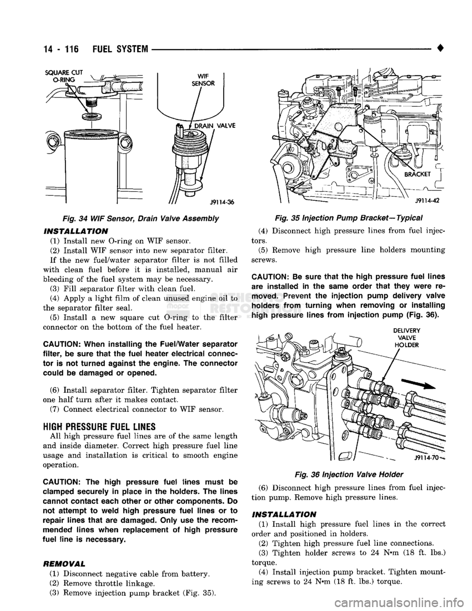
(1) Install new O-ring on WIF sensor.
(2) Install WIF sensor into new separator filter.
If the new fuel/water separator filter is not filled
with clean fuel before it is installed, manual air
bleeding of the fuel system may be necessary. (3) Fill separator filter with clean fuel.
(4) Apply a light film of clean unused engine oil to
the separator filter seal.
(5) Install a new square cut O-ring to the filter
connector on the bottom of the fuel heater.
CAUTION:
When installing
the
Fuel/Water separator
filter,
be
sure
that
the
fuel
heater
electrical
connec
tor
is not
turned
against
the
engine.
The
connector could
be
damaged
or
opened.
(6) Install separator filter. Tighten separator filter
one half turn after it makes contact.
(7) Connect electrical connector to WIF sensor.
HIGH
PRESSURE
FUEL LINES
All high pressure fuel lines are of the same length
and inside diameter. Correct high pressure fuel line
usage and installation is critical to smooth engine
operation.
CAUTION:
The
high pressure
fuel
lines must
be
clamped securely
in
place
in the
holders.
The
lines
cannot contact each other
or
other components.
Do
not
attempt
to
weld high pressure
fuel
lines
or to
repair lines
that
are
damaged. Only
use the
recom
mended lines when replacement
of
high pressure
fuel
line
is
necessary.
REMOVAL
(1) Disconnect negative cable from battery.
(2) Remove throttle linkage.
(3) Remove injection pump bracket (Fig. 35).
Fig.
35 Injection
Pump
Bracket—
Typical
(4) Disconnect high pressure lines from fuel injec
tors.
(5) Remove high pressure line holders mounting
screws.
CAUTION:
Be
sure
that
the
high pressure
fuel
lines
are installed
in the
same order
that
they
were
re
moved.
Prevent
the
injection
pump delivery valve
holders from turning when removing
or
installing
high
pressure lines from
injection
pump (Fig.
36).
Fig.
36 Injection
Valve
Holder
(6) Disconnect high pressure lines from fuel injec
tion pump. Remove high pressure lines.
INSTALLATION
(1) Install high pressure fuel lines in the correct
order and positioned in holders.
(2) Tighten high pressure fuel line connections.
(3) Tighten holder screws to 24 N-m (18 ft. lbs.)
torque.
(4) Install injection pump bracket. Tighten mount
ing screws to 24 N*m (18 ft. lbs.) torque.
Page 946 of 1502
PROPELLER
SHAFTS
16-1
PROPELLER
SHAFTS
CONTENTS
page
GENERAL
INFORMATION
1
TORQUE SPECIFICATIONS
PROPELLER
SHAFT REPLACEMENT
8
UNIVERSAL
JOINT
REPLACEMENT
SERVICE
DIAGNOSIS/PROCEDURES
3
page
15
10
GENERAL INFORMATION
PROPELLER
SHAFTS
The basic function of a propeller shaft is to trans
mit power from one point to another. The shaft is de
signed to send torque through an angle from the
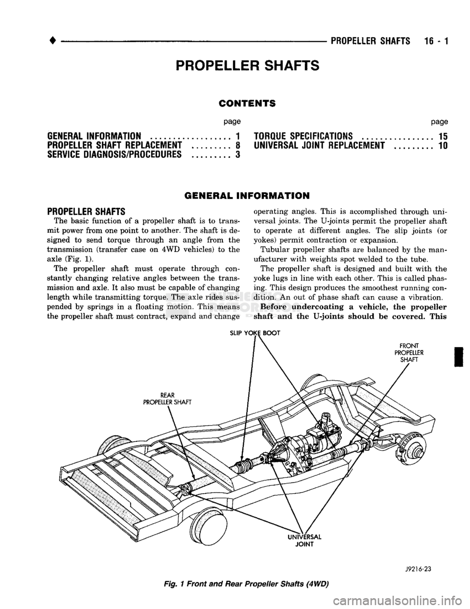
transmission (transfer case on 4WD vehicles) to the axle (Fig. 1). The propeller shaft must operate through con
stantly changing relative angles between the trans
mission and axle. It also must be capable of changing length while transmitting torque. The axle rides sus
pended by springs in a floating motion. This means
the propeller shaft must contract, expand and change operating angles. This is accomplished through uni
versal joints. The U-joints permit the propeller shaft
to operate at different angles. The slip joints (or
yokes) permit contraction or expansion.
Tubular propeller shafts are balanced by the man
ufacturer with weights spot welded to the tube.
The propeller shaft is designed and built with the
yoke lugs in line with each other. This is called phas ing. This design produces the smoothest running con
dition. An out of phase shaft can cause a vibration.
Before undercoating a vehicle, the propeller
shaft and the U-joints should be covered. This
SLIP
YOKE
BOOT
FRONT
PROPELLER SHAFT
REAR
PROPELLER SHAFT
Fig.
1 Front and Rear Propeller Shafts (4
WD)
J9216-23
Page 949 of 1502
16-4 PROPELLER SHAFTS
• (8) Run and accelerate the vehicle until vibration
occurs. Note the intensity and speed the vibration oc
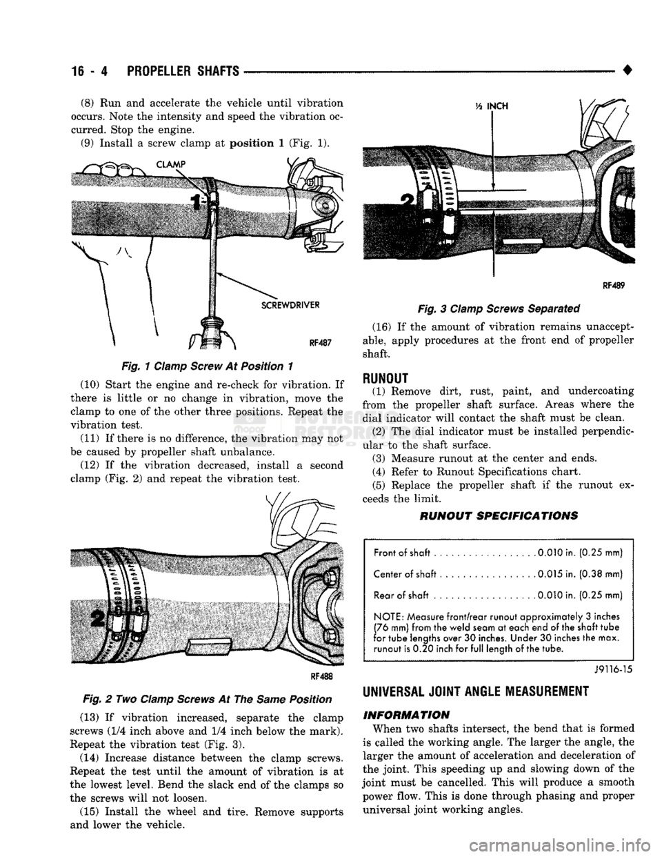
curred. Stop the engine. (9) Install a screw clamp at position I (Fig. 1).
Fig.
1 Clamp
Screw
At Position 1
(10) Start the engine and re-check for vibration. If
there is little or no change in vibration, move the clamp to one of the other three positions. Repeat the
vibration test.
(11) If there is no difference, the vibration may not
be caused by propeller shaft unbalance. (12) If the vibration decreased, install a second
clamp (Fig. 2) and repeat the vibration test.
Fig.
2 Two
Clamp
Screws
At The
Same
Position
(13) If vibration increased, separate the clamp
screws (1/4 inch above and 1/4 inch below the mark).
Repeat the vibration test (Fig. 3).
(14) Increase distance between the clamp screws.
Repeat the test until the amount of vibration is at
the lowest level. Bend the slack end of the clamps so the screws will not loosen.
(15) Install the wheel and tire. Remove supports
and lower the vehicle.
RF4B9
Fig.
3
Clamp
Screws
Separated (16) If the amount of vibration remains unaccept
able,
apply procedures at the front end of propeller
shaft.
RUNOUT (1) Remove dirt, rust, paint, and undercoating
from the propeller shaft surface. Areas where the dial indicator will contact the shaft must be clean. (2) The dial indicator must be installed perpendic
ular to the shaft surface. (3) Measure runout at the center and ends. (4) Refer to Runout Specifications chart.
(5) Replace the propeller shaft if the runout ex
ceeds the limit.
RUNOUT
SPECIFICATIONS
Front of shaft 0.010 in. (0.25 mm)
Center of shaft . 0.015 in. (0.38 mm) Rear of
shaft
.
0.010
in. (0.25 mm)
NOTE: Measure front/rear runout approximately 3 inches
(76 mm) from the weld seam at each end of the
shaft
tube
for tube lengths over 30 inches. Under 30 inches the max. runout is 0.20 inch for full length of
the
tube.
J9116-15
UNIVERSAL JOINT
ANGLE
MEASUREMENT
INFORMATION
When two shafts intersect, the bend that is formed
is called the working angle. The larger the angle, the
larger the amount of acceleration and deceleration of
the joint. This speeding up and slowing down of the
joint must be cancelled. This will produce a smooth power flow. This is done through phasing and proper universal joint working angles.
Page 952 of 1502
•
PROPELLER SHAFTS
16 - 7 ADJUSTMENT AT AXLE WITH LEAF SPRINGS
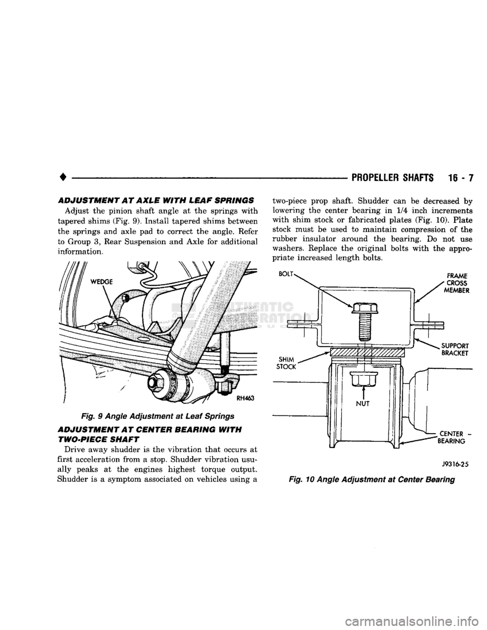
Adjust the pinion shaft angle at the springs with
tapered shims (Fig. 9). Install tapered shims between
the springs and axle pad to correct the angle. Refer to Group 3, Rear Suspension and Axle for additional information.
Fig. 9 Angle Adjustment at Leaf Springs
ADJUSTMENT AT CENTER BEARING WITH TWO-PIECE SHAFT
Drive away shudder is the vibration that occurs at
first acceleration from a stop. Shudder vibration usu ally peaks at the engines highest torque output.
Shudder is a symptom associated on vehicles using a two-piece prop shaft. Shudder can be decreased by
lowering the center bearing in 1/4 inch increments
with shim stock or fabricated plates (Fig. 10). Plate stock must be used to maintain compression of the
rubber insulator around the bearing. Do not use
washers. Replace the original bolts with the appro
priate increased length bolts.
J9316-25
Fig. 10 Angle Adjustment at Center Bearing
Page 1094 of 1502
•
AUTOMATIC
TRANSMISSION-32RH/3IRH/37RH/42RH/48RH
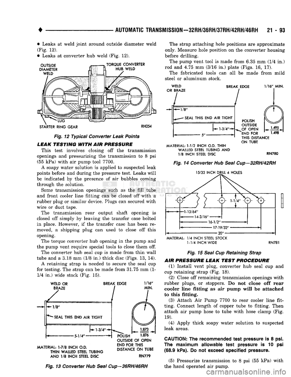
21 - 13 • Leaks at weld joint around outside diameter weld
(Fig. 12).
• Leaks at converter hub weld (Fig. 12).
OUTSIDE
DIAMETER
WELD
TORQUE CONVERTER
HUB WELD
"LUG
STARTER RING GEAR
RH254
Fig.
12 Typical Converter
Leak
Points
LEAK
TESTING
WITH AIR
PRESSURE
This test involves closing off the transmission
openings and pressurizing the transmission to 8 psi (55 kPa) with air pump tool 7700.
A soapy water solution is applied to suspected leak
points before and during the pressure test. Leaks will
be indicated by the presence of air bubbles coming
through the solution.
Some transmission openings such as the fill tube
and front cooler line fitting can be closed off with a
rubber plug or similar device. Plugs can secured with
wire or duct tape.
The transmission rear output shaft opening is
closed off simply by leaving the transfer case bolted
in place. However, if the transfer case has been re
moved, a shipping plug can used to close off this
opening. The torque converter hub opening in the pump and
the pump vent require special tools to close them off.
The converter hub seal cup is made from thin wall
tube and a 3.18 mm (1/8 in.) thick disc (Figs. 13, 14).
A retaining strap is needed to secure the seal cup
for testing. The strap can be made from 31.75 mm (1- 1/4 in.) wide stock (Fig. 15).
WELD OR
BRAZE
BREAK
EDGE
1/16"
MIN.
MATERIAL: 1-7/8 INCH O.D.
THIN
WALLED STEEL TUBING
AND 1/8 INCH STEEL DISC OUTSIDE OF OPEN
END FOR THIS
DISTANCE ON TUBE
RN779 The strap attaching hole positions are approximate
only. Measure hole position on the converter housing
before drilling.
The pump vent tool is made from 6.35 mm (1/4 in.)
rod and 4.75 mm (3/16 in.) plate (Figs. 16, 17). The fabricated tools can all be made from mild
steel or aluminum stock. WELD
OR BRAZE BREAK EDGE 1/16" MIN.
-«-l/8"
• SEAL THIS END AIR TIGHT
1-3/4"-*-
•
5"-
MATERIAL: 1-1/2 INCH O.D. THIN WALLED STEEL TUBING AND 1/8 INCH STEEL DISC POLISH
OUTSIDE
„OF OPEN
"END
FOR
THIS DISTANCE
ON TUBE
RN780
Fig.
14 Converter Hub
Seal
Cup-32RH/42RH
15/32 INCH DRILL 4 HOLES
MATERIAL: 1/4 INCH STEEL STOCK 1-1/4 INCH WIDE RN781
Fig.
13 Converter Hub
Seal
Cup-36RH/46RH
Fig.
15
Seal
Cup Retaining Strap
AIR
PRESSURE
LEAK
TEST
PROCEDURE
(1) Install vent plug, converter hub seal cup and
cup retaining strap (Fig. 18).
(2) Close off remaining transmission openings with
rubber plugs, or stoppers. Do not close off rear cooler line fitting as air pump will be attached
to this fitting.
(3) Attach Air Pump 7700 to rear cooler line fit
ting. Connect length of copper tube to fitting. Then attach air pump hose to tube with hose clamp (Fig.
19).
(4) Apply thick soapy water solution to suspected
leak areas.
CAUTION:
The
recommended
test
pressure
is 8
psi.
The
maximum
allowable
test
pressure
is 10 psi
(68.9 kPa).
Do not
exceed
specified
pressure.
(5) Pressurize transmission to 8 psi (55 kPa) with
the hand operated air pump.
Page 1148 of 1502
•
AUTOMATIC TRANSMISSION REMOVAL
AND
INSTALLATION
21 - 147
Fig.
10 Checking Torque Converter Seating (10) Move transmission forward. Then raise, lower
or tilt transmission to align converter housing with
dowels in engine block.
(11) Rotate converter until alignment mark scribed
on converter is aligned with mark on driveplate.
Off
set holes in plate are next to 1/8 in. hole in inner cir
cle of plate (Fig. 1).
(12) Carefully work transmission forward until
converter hub is seated.
(13) Install bolts attaching converter housing to
engine block. (14) Install crossmember and brackets.
(15) Lower transmission onto crossmember and in
sulator. Then install bolts attaching transmission
mount to crossmember.
(16) Remove fixture used to support engine.
(17) Connect wires to vehicle speed sensor.
(18) Install new plastic retainer grommet on any
shift linkage rod or lever that was disconnected. Old
grommets should not be reused. Use pry tool to re
move rod from grommet and cut away old grommet.
Use pliers to snap new grommet into lever and to
snap rod into grommet.
(19) Connect gearshift linkage and transmission
throttle cable to levers on manual valve shaft.
(20) Connect wires to park/neutral position switch,
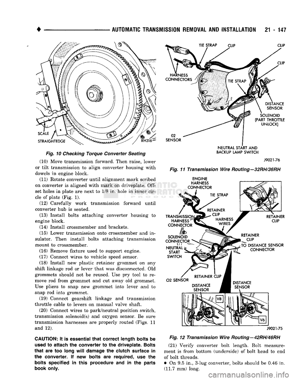
transmission solenoid(s) and oxygen sensor. Be sure
transmission harnesses are properly routed (Figs. 11 and 12).
CAUTION:
It is
essential
that
correct length bolts
be
used
to
attach
the
converter
to the
driveplate. Bolts
that
are too
long
will
damage
the
clutch surface
in the
converter.
If new
bolts
are
required,
use the
bolts
specified
in
this procedure
and in the
parts
book only.
SENSOR
NEUTRAL
START
AND
BACKUP
LAMP
SWITCH
J9021-76
Fig.
11
Transmission
Wire
Routing—32RH/36RH
ENGINE
J9021-75
Fig.
12
Transmission
Wire
Routing—42RH/46RH
(21) Verify converter bolt length. Bolt measure
ment is from bottom (underside) of bolt head to end of bolt threads.
• On 9.5 in., 3-lug converter, bolts should be 0.46 in. (11.7 mm) long.
Page 1150 of 1502
•
AUTOMATIC
TRANSMISSION
REMOVAL
AND
INSTALLATION
21 - 149
10).
Surface of converter lugs should be approxi
mately 13 mm (1/2 in.) to rear of straight edge when converter is fully seated.
(5) Temporarily secure converter in pump and
housing with C-clamp attached to housing edge, or
with metal strap attached across converter housing.
(6) Position transmission on jack. Secure transmis
sion to jack with safety chains.
(7) Check condition of converter driveplate. Re
place plate if cracked, distorted or damaged. If driveplate replacement was necessary, be sure
transmission dowel pins are seated in engine block and protrude far enough to held transmis sion in alignment.
(8) Coat pilot hub of torque converter with trans
mission fluid.
(9) Raise transmission and align converter with
drive plate and crankshaft.
(10) Move transmission forward. Then raise, lower
or tilt transmission to align converter housing with
dowels on engine block.
(11) Rotate converter to align marks scribed on
converter and driveplate. Offset holes in plate are
next to 1/8 in. hole in inner circle of plate (Fig. 1).
(12) Carefully work transmission forward and over
engine block dowels until converter hub is seated in crankshaft.
(13) Install bolts attaching converter housing to
engine.
(14) Install crossmember.
(15) Lower transmission onto crossmember and in
stall bolts attaching transmission and insulator to
crossmember (Figs. 4 and 5). (16) Remove fixture used to support engine.
(17) Connect vehicle speed sensor wires. (18) Install new plastic retainer grommet on any
shift linkage rod or lever that was disconnected. Old
grommets should not be reused. Use pry tool to re
move rod from grommet and cut away old grommet.
Use pliers to snap new grommet into lever and to snap rod into grommet. (19) Connect gearshift and throttle linkage to
transmission. (20) Connect wires to park/neutral position switch,
transmission solenoids and to oxygen sensor. Be sure
transmission harnesses are properly routed.
CAUTION:
It is essential
that
correct length
bolts
be
used
to
attach
the
converter
to the
driveplate.
Bolts
that
are too long
will
damage
the
clutch
surface
in
the converter. If new
bolts
are required, use the
bolts
specified in this procedure and in the parts
book
only.
(21) Verify converter bolt length. Bolt measure
ment is from bottom (underside) of bolt head to end
of bolt threads. • On 9.5 in., 3-lug converter, bolts should be 11.7
mm (0.46 in.) long.
• On 9.5 in., 4-lug converter, bolts should be 13.2
mm (0.52 in.) long.
• On 10.0 in., 4-lug converter, bolts should be 13.2
mm (0.52 in.) long.
• On 10.75 in., 4-lug converter, bolts should be 11.2
mm (0.44 in.) long.
(22) Install torque converter bolts. Tighten bolts as
follows:
• On models with 9.5 in., 3-lug converter, tighten
bolts to 54 Nnn (40 ft. lbs.).
• On models with 9.5 in., 4-lug converter, tighten
bolts to 74 Nnn (55 ft. lbs.).
• On models with 10.0 in., 4-lug converter, tighten
bolts to 74 Nnn (55 ft. lbs.) torque.
• On models with 10.75 in., 4-lug converter, tighten
bolts to 31 Nnn (270 in. lbs.).
• On diesel models with 12.2 in. converter, tighten
bolts to 47 Nnn (35 ft. lbs.) torque.
(23) Install converter housing access cover. (24) Install starter motor and cooler line bracket.
(25) Connect cooler lines to transmission.
(26) Install transmission fill tube. Install new
O-ring seal on tube before installation.
(27) Install any exhaust components removed for
service access. (28) Support transfer case on transmission jack.
Secure transfer case to jack with safety chains. (29) Install gasket on transmission adapter. Coat
gasket with Mopar perfect, seal, or silicone sealer be
forehand. (30) Install transfer case on transmission. Tighten
transfer case attaching nuts to 47 Nnn (35 ft. lbs.) torque. (31) Remove jack supporting transfer case.
(32) Connect transfer case shift lever to range le
ver. (33) Align and install propeller shafts. Tighten
clamp bolts to 19 Nnn 170 in. lbs.) torque. (34) Install transfer case skid plate and crossmem
ber. (35) Lower vehicle.
(36) Fill transmission with Mopar ATF Plus, Type
7176, or Mopar Dexron II if ATF Plus is not readily
available. (37) Check and adjust gearshift, throttle valve and
transfer case shift linkages if necessary.
OVERDRIVE
UNIT
REMOVAL—42RH/46RH
The following removal and installation procedures
apply to the 42RH/46RH overdrive unit only. If the
complete transmission assembly must be removed,
refer to the Transmission And Converter Removal and Installation procedures. (1) Shift transmission into Park.
(2) Raise vehicle.
Page 1329 of 1502
21
- 328
OVERDRIVE UNIT OVERHAUL—42RH/46RH
•
Fig.
21 Removing/Installing Output Shaft Front Bearing WARNING: THE NEXT STEP IN GEARTRAIN
DISASSEMBLY INVOLVES COMPRESSING THE DI
RECT CLUTCH SPRING. IT IS EXTREMELY IMPOR
TANT THAT PROPER EQUIPMENT BE USED TO COMPRESS THE SPRING AS SPRING FORCE IS
APPROXIMATELY 800 POUNDS. USE SPRING COM PRESSOR TOOL C-6227-1 AND A HYDRAULIC-
TYPE SHOP PRESS WITH A MINIMUM RAM
TRAVEL OF 5-6 INCHES. THE PRESS MUST ALSO HAVE A BED THAT CAN BE ADJUSTED UP OR
DOWN AS REQUIRED. RELEASE CLUTCH SPRING
TENSION SLOWLY AND COMPLETELY TO AVOID PERSONAL INJURY.
(7) Mount geartrain assembly in shop press
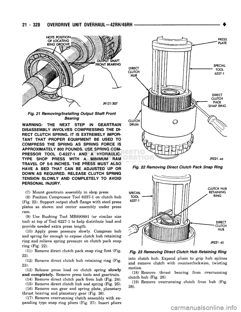
(8) Position Compressor Tool 6227-1 on clutch hub
(Fig. 22). Support output shaft flange with steel press
plates as shown and center assembly under press ram.
(9) Use Bushing Tool MB990891 (or similar size
tool) at top of Tool 6227-1 to help distribute load and
provide needed extra press length.
(10) Apply press pressure slowly. Compress hub
and spring far enough to expose clutch hub retaining
ring and relieve spring pressure on clutch pack snap
ring (Fig. 22).
(11) Remove direct clutch pack snap ring first (Fig.
22).
(12) Remove direct clutch hub retaining ring (Fig.
23).
(13) Release press load on clutch spring slowly
and completely. Remove press tools and geartrain. (14) Remove direct clutch pack from hub (Fig. 24). (15) Remove direct clutch hub and spring (Fig. 25).
(16) Remove sun gear and spring plate, planetary
thrust bearing and planetary gear (Fig. 26). (17) Remove overrunning clutch assembly with ex
panding type snap ring pliers (Fig. 27). Insert pliers
Fig.
22
Removing
Direct
Clutch
Pack
Snap
Ring
Fig.
23
Removing
Direct
Clutch
Hub Retaining
Ring
into clutch hub. Expand pliers to grip hub splines and remove clutch with counterclockwise, twisting
motion.
(18) Remove thrust bearing from overrunning
clutch hub (Fig. 28). (19) Remove overrunning clutch from hub (Fig.
28).