1993 DODGE TRUCK Neutral safety switch
[x] Cancel search: Neutral safety switchPage 31 of 1502

0 - 12
LUBRICATION
AND
MAINTENANCE
• A vehicle equipped with SAE approved sling-type
towing equipment can be used (Fig. 10). However,
many vehicles are equipped with air dams, spoilers, and/or ground effect panels. In this case a wheel-lift
towing vehicle or a flat-bed hauling vehicle is recom mended (Fig. 10). If a flat bed device is used, the ap
proach angle should not exceed 15 degrees.
GROUND CLEARANCE The lifted wheels of the disabled vehicle should be
a minimum of 10 cm (4 in.) off the ground. Make
sure there is enough clearance at the opposite end.
This is critical when towing over rough terrain. If necessary, the rear ground clearance can be increased by removing the wheels from the lifted end
and then towing with the lifted end closer to the
ground. If the rear wheels are removed, secure the
brake drums. A 20 cm (8 in.) ground clearance must
be maintained between brake drums or rotors and the ground.
SAFETY PRECAUTIONS The following safety precautions must be consid
ered when preparing for and during a vehicle towing operation:
• Remove exhaust pipe tips that interfere with the
tow sling and crossbar • Padding should be placed between the tow sling/
crossbar and any painted surfaces
• If the vehicle is damaged, secure the loose and pro
truding parts
• Always use a safety chain system that is indepen dent of the lifting and towing equipment
• When placing tow hooks on the rear axle, position them so they do not damage the brake tubing or
hoses
• Do not allow any of the towing equipment to con
tact the fuel tank
• Do not tow the vehicle by connecting to the front
or rear shock absorbers
• The operator should not go under a vehicle while
it is lifted by the towing equipment. The vehicle
should first be supported by safety stands
• Do not allow passengers in a vehicle being towed
• Observe all state and local laws involving warning signals, night illumination, speed, etc.
• Do not exceed a towing speed of 48 km/h (30 mph)
• Avoid towing distances of more than 24 km (15
miles) whenever possible • Do not attach tow chains or a tow sling to a
bumper, the steering linkage, the universal joints, or a drive shaft
REAR-END RAISED TOWING It is recommended that the rear-end raised towing
method be used. Vehicles can be towed with the front
wheels on the ground for extended distances at speeds not exceeding 48 km/h (30 mph) (Fig. 11). (1) Attach the J-hooks around the axle shaft tubes
outboard of the rear springs. (2) Position and center the sling under and for
ward of the rear bumper. (3) Attach safety chains (with pads) at each end of
the rear bumper.
(4) Turn the ignition switch to the OFF position to
unlock the steering wheel. (5) Clamp the steering wheel with the front wheels
in the straight ahead position.
CAUTION:
Do not use the steering
column
lock
to
secure
front
wheel
in the straight-ahead
position.
(6) Shift the transmission to NEUTRAL.
POSITION CENTER BAR FORWARD
OF
BUMPER
-
/
J-HOOKS OUTBOARD
OF
SPRINGS
RN967A
Fig. 11 Rear-End
Raised
Towing
FRONT'END RAISED TOWING If a vehicle cannot be towed from the rear, the
front-end raised towing method normally can be
used (Fig. 12). (1) Center the sling with the bumper and position
it at the frame front crossmember.
CAUTION:
Use tow
chains
with
J-hooks
for
con
necting
to the
disabled
vehicle's
lower
suspension
arms.
Never use
T-hooks.
(2) Route the J-hooks and tow chains over the
steering linkage outboard of the coil spring.
(3) Attach the J-hooks to the outer end of the
lower suspension arms.
(4) Raise the vehicle.
(5.) Attach the safety chains to the disabled vehicle
at the frame rails.
Vehicles equipped with a MANUAL TRANSMIS
SION can be towed with the rear wheels on the
Page 330 of 1502
•
ELECTRICAL
8A - 9
ENGINE STARTER MOTOR TEST PROCEDURES
GENERAL INFORMATION
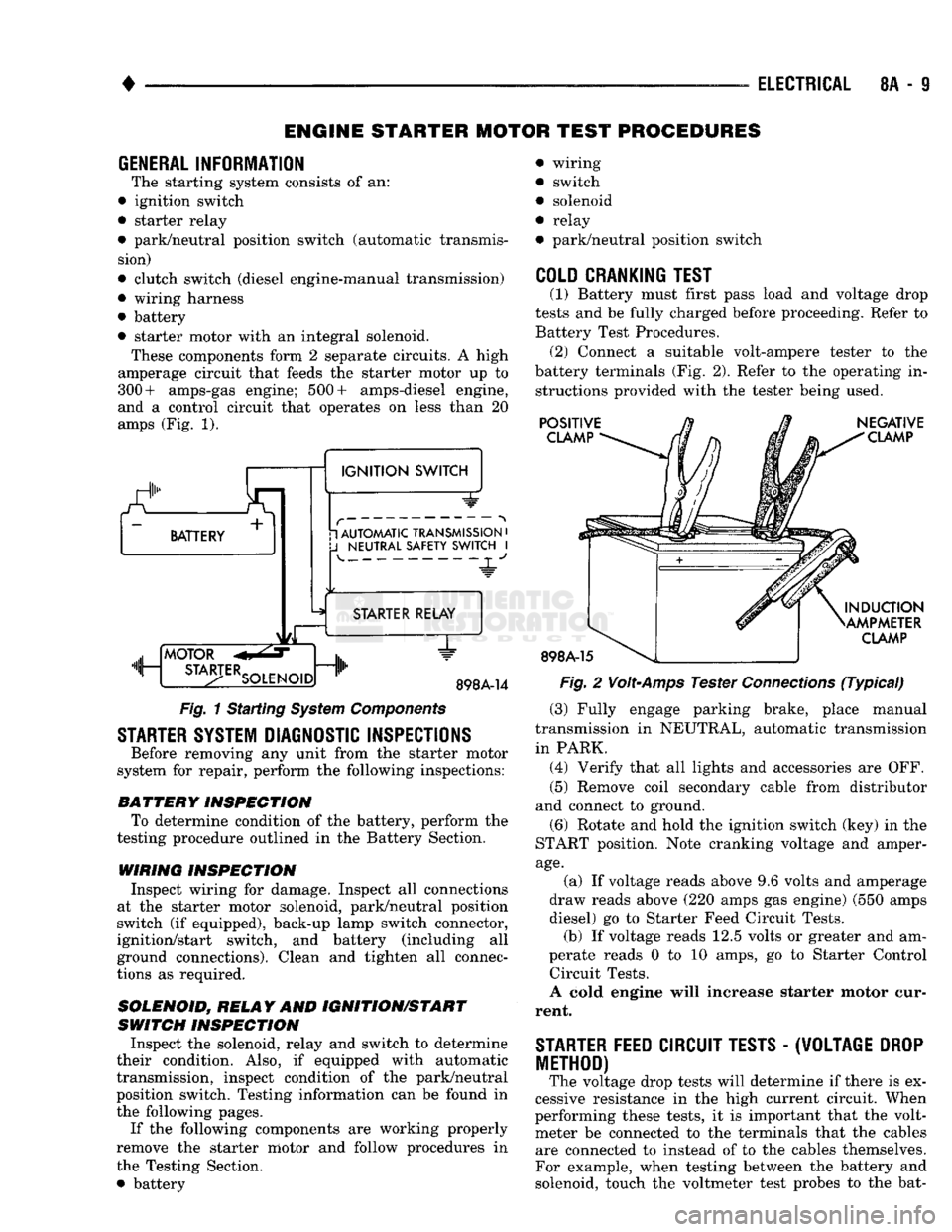
The starting system consists of an:
• ignition switch
• starter relay
• park/neutral position switch (automatic transmis sion)
• clutch switch (diesel engine-manual transmission)
• wiring harness
• battery
• starter motor with an integral solenoid. These components form 2 separate circuits. A high
amperage circuit that feeds the starter motor up to
300+ amps-gas engine; 500+ amps-diesel engine,
and a control circuit that operates on less than 20
amps (Fig. 1).
a.
BATTERY +
1
IGNITION
SWITCH 1 AUTOMATIC TRANSMISSION
•
J
NEUTRAL SAFETY SWITCH
I 4-
"JL"
MOTOR
m, ...
STA3-TERSOLENO,Dnlh
STARTER RELAY
1"
898A-14
Fig.
1 Starting
System
Components
STARTER SYSTEM DIAGNOSTIC INSPECTIONS
Before removing any unit from the starter motor
system for repair, perform the following inspections:
BATTERY
INSPECTION
To determine condition of the battery, perform the
testing procedure outlined in the Battery Section.
WIRING INSPECTION
Inspect wiring for damage. Inspect all connections
at the starter motor solenoid, park/neutral position
switch (if equipped), back-up lamp switch connector,
ignition/start switch, and battery (including all
ground connections). Clean and tighten all connec
tions as required.
SOLENOID, RELAY
AND
IGNITION/START
SWITCH
INSPECTION
Inspect the solenoid, relay and switch to determine
their condition. Also, if equipped with automatic
transmission, inspect condition of the park/neutral position switch. Testing information can be found in
the following pages.
If the following components are working properly
remove the starter motor and follow procedures in
the Testing Section. • battery wiring
switch
solenoid
relay
park/neutral position switch
COLD CRANKING TEST
(1) Battery must first pass load and voltage drop
tests and be fully charged before proceeding. Refer to Battery Test Procedures. (2) Connect a suitable volt-ampere tester to the
battery terminals (Fig. 2). Refer to the operating in structions provided with the tester being used.
POSITIVE
CLAMP
898A-15
NEGATIVE
CLAMP
INDUCTION
AMPMETER
CLAMP
Fig.
2
Volt-Amps
Tester
Connections
(Typical)
(3) Fully engage parking brake, place manual
transmission in NEUTRAL, automatic transmission
in PARK. (4) Verify that all lights and accessories are OFF. (5) Remove coil secondary cable from distributor
and connect to ground.
(6) Rotate and hold the ignition switch (key) in the
START position. Note cranking voltage and amper
age.
(a) If voltage reads above 9.6 volts and amperage
draw reads above (220 amps gas engine) (550 amps
diesel) go to Starter Feed Circuit Tests. (b) If voltage reads 12.5 volts or greater and am-
perate reads 0 to 10 amps, go to Starter Control Circuit Tests.
A cold engine will increase starter motor cur
rent.
STARTER
FEED
CIRCUIT TESTS
-
(W0LTAGE
DROP
METHOD)
The voltage drop tests will determine if there is ex
cessive resistance in the high current circuit. When
performing these tests, it is important that the volt meter be connected to the terminals that the cables are connected to instead of to the cables themselves.
For example, when testing between the battery and
solenoid, touch the voltmeter test probes to the bat-
Page 613 of 1502
9
- 8
ENGINES
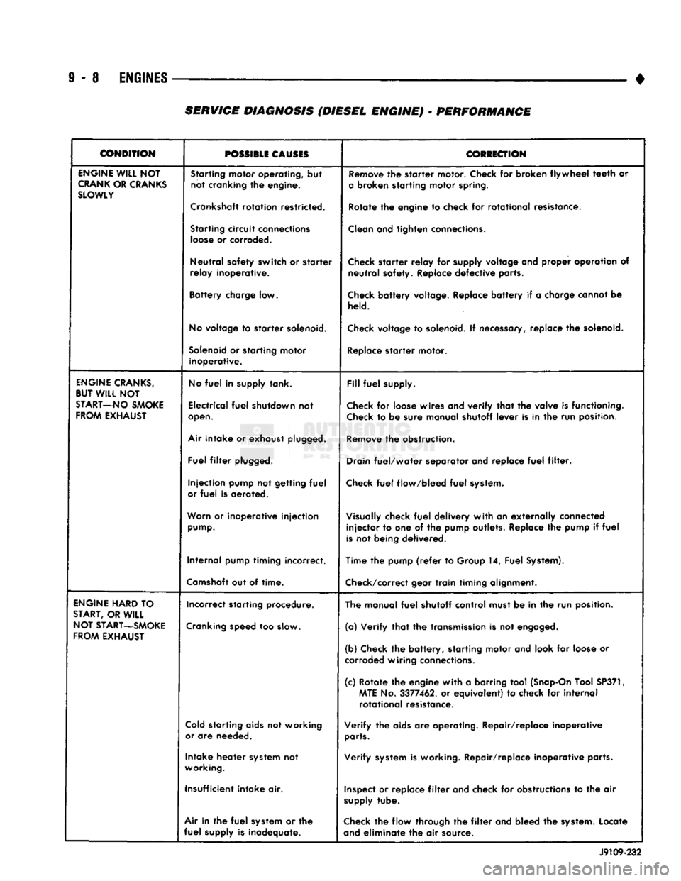
• SERVICE DIAGNOSIS (DIESEL ENGINE) - PERFORMANCE
CONDITION
POSSIBLE
CAUSES
COtiECTION
ENGINE
WILL
NOT
CRANK
OR
CRANKS
SLOWLY
Starting
motor operating, but
not cranking the engine.
Crankshaft
rotation restricted.
Starting
circuit
connections
loose
or corroded.
Neutral safety switch or starter
relay inoperative.
Battery charge low.
No
voltage to starter
solenoid.
Solenoid
or starting motor inoperative.
Remove
the starter motor. Check for broken flywheel
teeth
or
a
broken starting motor
spring.
Rotate the engine to check for rotational resistance.
Clean
and tighten
connections.
Check
starter relay for
supply
voltage and proper operation of neutral safety. Replace defective parts.
Check
battery voltage. Replace battery if a charge cannot be
held.
Check
voltage to
solenoid.
If
necessary,
replace the
solenoid.
Replace
starter motor.
ENGINE
CRANKS,
BUT
WILL
NOT
START—NO
SMOKE
FROM
EXHAUST
No
fuel
in supply tank.
Electrical
fuel
shutdown not
open.
Air
intake or exhaust
plugged.
Fuel
filter
plugged.
Injection pump not getting
fuel
or
fuel
is aerated.
Worn
or inoperative injection
pump.
Internal pump timing incorrect.
Camshaft
out of time.
Fill
fuel
supply.
Check
for
loose
wires and verify that the valve is functioning.
Check
to be sure manual shutoff lever is in the run position.
Remove
the obstruction.
Drain
fuel/water separator and replace
fuel
filter.
Check
fuel
flow/bleed
fuel
system.
Visually
check
fuel
delivery with an externally connected injector to one of the pump outlets. Replace the pump if
fuel
is
not being delivered.
Time the pump
(refer
to Group 14, Fuel
System).
Check/correct
gear train timing alignment.
ENGINE
HARD
TO
START,
OR
WILL
NOT
START—SMOKE
FROM
EXHAUST
Incorrect starting procedure.
Cranking
speed too
slow.
Cold
starting
aids
not working
or
are needed.
Intake heater
system
not
working.
Insufficient intake air.
Air
in the
fuel
system
or the
fuel
supply is inadequate. The manual
fuel
shutoff control must be in the run position.
(a) Verify that the
transmission
is not
engaged.
(b) Check the battery, starting motor and look for
loose
or
corroded
wiring
connections.
(c) Rotate the engine with a barring tool
(Snap-On
Tool
SP371,
MTE
No. 3377462, or equivalent) to check for internal rotational resistance.
Verify the
aids
are operating. Repair/replace inoperative
parts.
Verify
system
is working. Repair/replace inoperative parts.
Inspect
or replace
filter
and check for
obstructions
to the air
supply
tube.
Check
the flow through the
filter
and bleed the
system.
Locate
and
eliminate the air source. J9109-232
Page 898 of 1502
•
FUEL SYSTEM
14-79
OVERDRIVE/OVERRIDE SWITCH-PCM
INPUT
The overdrive/override switch is not used with
manual transmissions. On vehicles equipped with overdrive, the PCM reg
ulates the 3-4 overdrive upshift and downshift
through the overdrive solenoid. An override switch is located on the instrument panel. The overdrive/override switch is a momentary con
tact switch. The switch contacts are normally open. When the switch is activated, the PCM will receive a ground signal. The transmission will not enter over
drive when the operator presses the override switch.
The transmission downshifts if the operator presses
the override switch while in overdrive.
COOLANT TEMPERATURE SENSOR The coolant temperature sensor is not used with
manual transmissions.
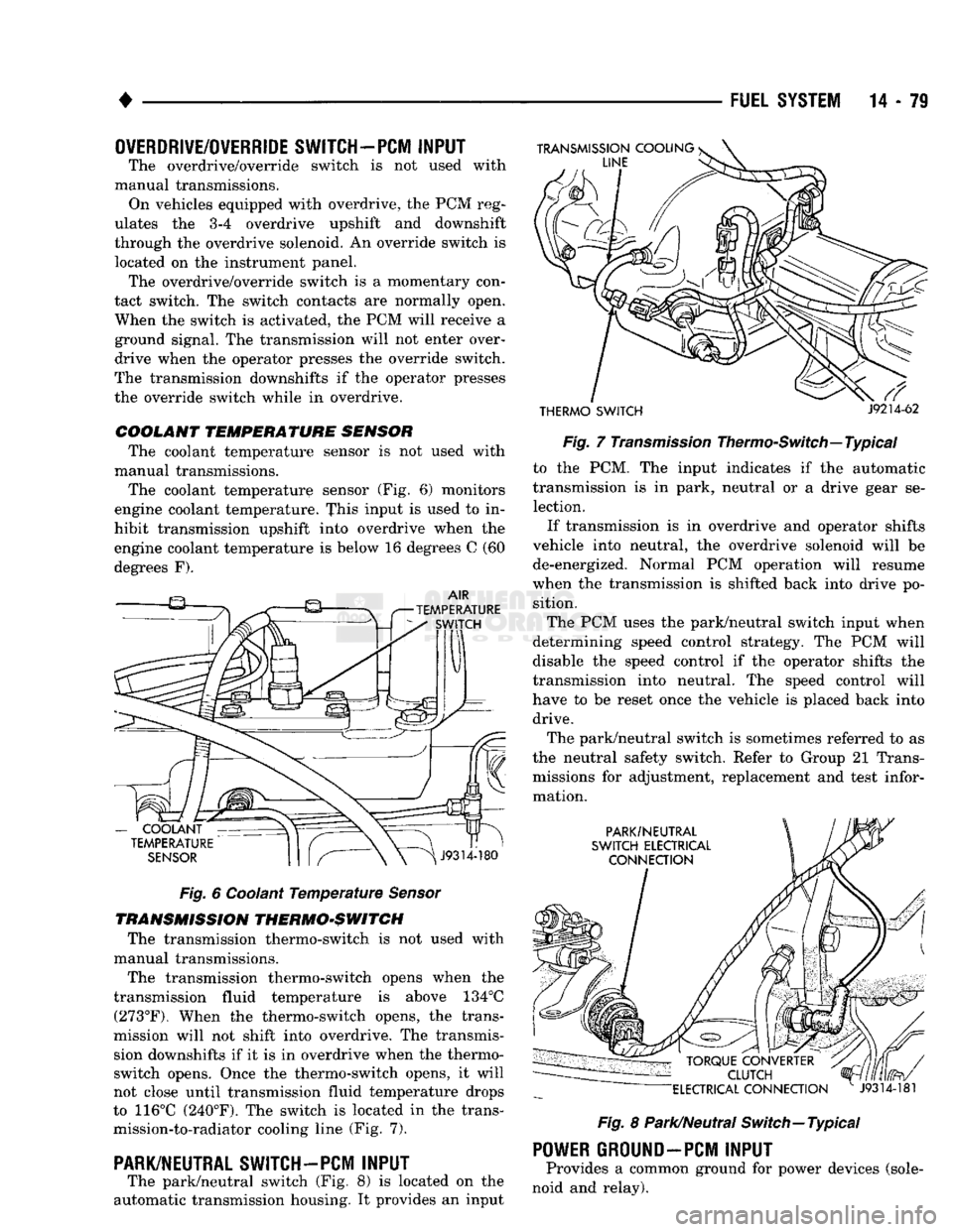
The coolant temperature sensor (Fig. 6) monitors
engine coolant temperature. This input is used to in
hibit transmission upshift into overdrive when the
engine coolant temperature is below 16 degrees C (60
degrees F).
Fig.
6 Coolant
Temperature
Sensor
TRANSMISSION THERMO-SWITCH The transmission thermo-switch is not used with
manual transmissions.
The transmission thermo-switch opens when the
transmission fluid temperature is above 134°C (273°F). When the thermo-switch opens, the trans
mission will not shift into overdrive. The transmis sion downshifts if it is in overdrive when the thermo-
switch opens. Once the thermo-switch opens, it will
not close until transmission fluid temperature drops
to 116°C (240°F). The switch is located in the trans mission-to-radiator cooling line (Fig. 7).
PARK/NEUTRAL SWITCH-PCM
INPUT
The park/neutral switch (Fig. 8) is located on the
automatic transmission housing. It provides an input
THERMO SWITCH
J9214-62
Fig.
7
Transmission
Thermo-Switch—Typical to the PCM. The input indicates if the automatic
transmission is in park, neutral or a drive gear se lection.
If transmission is in overdrive and operator shifts
vehicle into neutral, the overdrive solenoid will be de-energized. Normal PCM operation will resume
when the transmission is shifted back into drive po sition.
The PCM uses the park/neutral switch input when
determining speed control strategy. The PCM will
disable the speed control if the operator shifts the
transmission into neutral. The speed control will
have to be reset once the vehicle is placed back into drive.
The park/neutral switch is sometimes referred to as
the neutral safety switch. Refer to Group 21 Trans missions for adjustment, replacement and test infor
mation.
Fig.
8 Park/Neutral Switch—Typical
POWER
GROUND-PCM
INPUT
Provides a common ground for power devices (sole
noid and relay).
Page 1004 of 1502
•
NV4500 MANUAL
TRANSMISSION
21 - 3
PTO
COVER
J9221-14
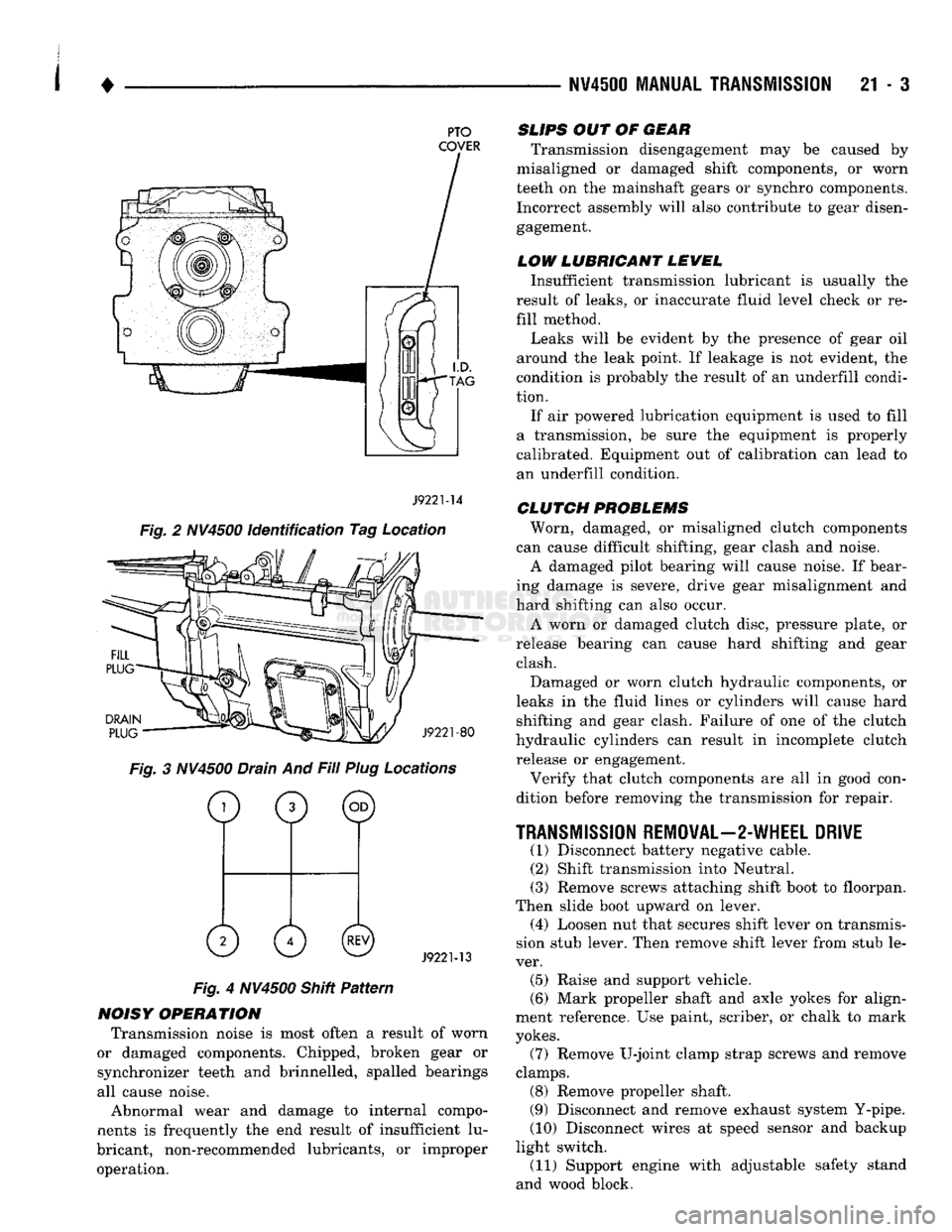
Fig. 2 NV4500 identification Tag Location
DRAIN
PLUG
J9221-80
Fig. 3 NV4500 Drain And Fill Plug Locations
o
0 ©
0 0©
J9221-13
Fig. 4 NV4500 Shitt Pattern
NOISY OPERATION Transmission noise is most often a result of worn
or damaged components. Chipped, broken gear or
synchronizer teeth and brinnelled, spalled bearings
all cause noise.
Abnormal wear and damage to internal compo
nents is frequently the end result of insufficient lu
bricant, non-recommended lubricants, or improper operation.
SLIPS
OUT OF
GEAR
Transmission disengagement may be caused by
misaligned or damaged shift components, or worn
teeth on the mainshaft gears or synchro components. Incorrect assembly will also contribute to gear disengagement.
LOW LUBRICANT LEWEL
Insufficient transmission lubricant is usually the
result of leaks, or inaccurate fluid level check or re
fill method.
Leaks will be evident by the presence of gear oil
around the leak point. If leakage is not evident, the
condition is probably the result of an underfill condi
tion.
If air powered lubrication equipment is used to fill
a transmission, be sure the equipment is properly
calibrated. Equipment out of calibration can lead to
an underfill condition.
CLUTCH
PROBLEMS
Worn, damaged, or misaligned clutch components
can cause difficult shifting, gear clash and noise.
A damaged pilot bearing will cause noise. If bear
ing damage is severe, drive gear misalignment and
hard shifting can also occur.
A worn or damaged clutch disc, pressure plate, or
release bearing can cause hard shifting and gear clash.
Damaged or worn clutch hydraulic components, or
leaks in the fluid lines or cylinders will cause hard shifting and gear clash. Failure of one of the clutch
hydraulic cylinders can result in incomplete clutch release or engagement.
Verify that clutch components are all in good con
dition before removing the transmission for repair.
TRANSMISSION
REMOVAL—2-WHEEL DRIVE
(1) Disconnect battery negative cable. (2) Shift transmission into Neutral.
(3) Remove screws attaching shift boot to floorpan.
Then slide boot upward on lever. (4) Loosen nut that secures shift lever on transmis
sion stub lever. Then remove shift lever from stub le
ver. (5) Raise and support vehicle.
(6) Mark propeller shaft and axle yokes for align
ment reference. Use paint, scriber, or chalk to mark
yokes.
(7) Remove U-joint clamp strap screws and remove
clamps. (8) Remove propeller shaft.
(9) Disconnect and remove exhaust system Y-pipe.
(10) Disconnect wires at speed sensor and backup
light switch. (11) Support engine with adjustable safety stand
and wood block.
Page 1005 of 1502
21
- 4
NV4500 MANUAL TRANSMISSION
(12) If transmission is to be disassembled for re
pair, remove drain plug and drain lubricant from transmission.
(13) move bolts/nuts attaching transmission to rear
mount.
(14) Support transmission with a transmission
jack. Secure transmission to jack with safety chains.
(15) Remove rear crossmember,
(16) Remove bolts attaching clutch slave cylinder
to clutch housing. Then move cylinder aside for
working clearance.
(17) Remove transmission harness wires from clips
on transmission shift cover. (18) Remove bolts attaching transmission to clutch
housing. (19) Slide transmission and jack rearward until
drive gear clears clutch housing. (20) Lower transmission jack and remove trans
mission from under vehicle. (21) If transmission will be overhauled, clean
transmission exterior with solvent or with steam gun.
TRANSMISSION
INSTALLATION—2-WHEEL DRIVE
(1) Apply light coat of Mopar high temperature
bearing grease to contact surfaces of following com
ponents: • drive gear splines and pilot bearing hub
• release bearing slide surface of front retainer
• pilot bearing • release bearing bore
• release fork
• release fork ball stud
• propeller shaft slip yoke (2) Fill transmission with recommended lubricant.
Correct fill level is bottom edge of fill plug hole. (3) Mount transmission on jack and position trans
mission under vehicle. (4) Raise transmission until drive gear is centered
in release bearing and clutch disc hub. (5) Move transmission forward and start drive gear
in release bearing, clutch disc and pilot bushing. (6) Work transmission forward until seated against
clutch housing. Do not allow transmission to remain
unsupported after drive gear has entered clutch disc. (7) Install and tighten transmission-to-clutch hous
ing bolts to 108 N*m (80 ft. lbs.) torque. (8) Install clutch slave cylinder. (9) Connect speed sensor and backup light switch
wires.
(10) Position transmission harness wires in clips
on shift cover. (11) Install transmission mount on transmission or
rear crossmember. (12) Install rear crossmember.
(13) Remove transmission jack and engine support
fixture. (14) Align and connect propeller shaft. (15) Fill transmission with required lubricant, if
necessary. (16) Lower vehicle.
(17) Install shift lever on transmission stub lever.
(18) Install shift boot and bezel. (19) Connect battery negative cable.
TRANSMISSION REMOVAL—4-WHEEL DRIVE
(1) Disconnect battery negative cable.
(2) Shift transmission into Neutral.
(3) Remove shift lever boot and bezel. (4) Loosen nut attaching shift lever to transmis
sion stub lever and remove shift lever from stub le
ver. (5) Raise- vehicle.
(6) Remove skid plate if equipped.
(7) If transmission will be disassembled for repair,
remove drain plug and drain lubricant from trans
mission. (8) Mark propeller shafts and yokes for assembly
reference. (9) Disconnect propeller shafts and remove propel
ler shafts. (10) Disconnect and remove exhaust system
Y-pipe. Then disconnect and lower remaining ex
haust pipes for clearance as necessary. (11) Support engine with adjustable safety stand.
(12) Disconnect speed sensor wires and disconnect
speedometer cable, if equipped. (13) Disconnect backup light switch wires.
(14) Disconnect transfer case shift linkage at
transfer case range lever. (15) Remove bolts/nuts attaching transmission to
rear support. (16) Remove crossmember bolts/nuts and remove
crossmember. (17) Support transfer case with transmission jack.
Secure transfer case to jack with safety chains. (18) Remove transfer case attaching nuts.
(19) Move transfer case rearward until input gear
clears transmission mainshaft. (20) Lower transfer case assembly and move it
from under vehicle. (21) If transmission is being removed for repair,
remove drain plug and drain lubricant from trans mission.
(22) Support transmission with transmission jack.
Secure transmission to jack with safety chains.
(23) Remove transmission harness from retaining
clips on transmission shift cover. (24) Remove bolts/nuts attaching transmission
mount to rear crossmember.
(25) Remove rear crossmember.
(26) Remove clutch slave cylinder splash shield, if
equipped.
(27) Loosen clutch slave cylinder attaching nuts
until cylinder piston rod is clear of release lever.
This reduces pressure on lever and release bearing
Page 1053 of 1502
21 - 52 G360
MANUAL
TRANSMISSION
• (12) Disconnect wires at vehicle speed sensor and
backup light switch.
(13) Disconnect transfer case shift lever from lever
on transfer case.
(14) Temporarily support transmission with adjust
able jack stand. Then support transfer case with
transmission jack.
(15) Remove nuts attaching transfer case to trans
mission adapter and move transfer case away from
transmission rear retainer.
(16) Lower transfer case and move it from under
vehicle. Remove transfer case from transmission jack and place transfer case on workbench.
(17) Support transmission with transmission jack.
Secure transmission to jack with safety chains. Then
remove jack stand previously used to support trans
mission.
(18) Spread clamps that secure switch wires to
transmission top cover and remove wires from clamps. Move wires aside to protect them and pro
vide working clearance.
(19) Remove bolts attaching transmission rear
mount to crossmember.
(20) On some models, it is necessary to remove
screws attaching fuel line clamps to driver side
frame rail. Three clamps must be removed to so fuel lines can be moved for access to crossmember bolts at
this side of frame rail.
(21) Remove left and right crossmember-to-frame
braces and remove crossmember.
(22) Remove clutch slave cylinder shield.
(23) Loosen clutch slave cylinder attaching nuts
until cylinder piston rod is clear of release lever (Fig.
20).
This reduces pressure on lever and release bear
ing making transmission removal/installation easier. Cylinder does not have to be removed completely.
(24) Remove bolts attaching transmission to clutch
housing and remove transmission. Rock transmission slightly to help free input shaft from clutch disc and
release bearing.
(25) Support engine with wood block and another
adjustable jack stand.
TRANSMISSION
INSTALLATION—4-WHEEL
DRIVE
(1) Mount transmission on jack stand. Secure
transmission to jack with safety chains.
(2) Apply light coat of Mopar high temperature
bearing grease to contact surfaces of input shaft (Fig. 20) and following components:
CAUTION:
Do not use
excessive
amounts
of
grease.
This
practice
could
result in contamination of the
clutch
disc.
• input shaft splines and pilot bearing hub
• release bearing slide surface of front retainer
• pilot bushing
• release bearing bore
• release fork
• release fork ball stud • propeller shaft slip yoke
(3) Align transmission and clutch housing. Move
transmission forward and start input shaft into re lease bearing and hub of clutch disc. (4) Rotate output shaft with socket or yoke to align
input shaft and clutch disc splines. If input shaft will
not rotate enough in neutral to align splines, it will
be necessary to shift transmission into third or fourth gear with screwdriver. (5) Seat transmission against clutch housing and
align bolt holes in transmission and housing. (6) Install and tighten transmission-to-clutch hous
ing bolts to 68 N-m (50 ft. lbs.). (7) Install rear crossmember and mount. Start all
crossmember bolts/nuts then tighten them to 68 N*m (50 ft. lbs.) torque. (8) Remove transmission jack.
(9) Install screws that attach fuel line clamps to
driver side frame rail. (10) Align clutch slave cylinder in housing and
tighten cylinder attaching nuts. (11) Install clutch slave cylinder shield.
(12) Secure backup light and vehicle speed sensor
wires in clips at top of transmission. Route wires across top of transmission to sensor and switch and
connect wires.
(13) Install gasket and transfer case on transmis
sion rear retainer. Tighten transfer case attaching
nuts to 47 N-m (35 ft. lbs.) torque. (14) Check transmission and transfer case lubri
cant levels. Add lubricant if necessary and install fill
plugs.
(15) Connect transfer case shift lever to lever on
transfer case.
(16) Align and install propeller shafts. Tighten
U-joint clamp bolts to 19 N-m (14 ft. lbs.). (17) Install skid plate and crossmember. Tighten
skid plate and crossmember bolts/nuts to 41 N—m
(30 ft. lbs.) torque.
(18) Lower vehicle.
(19) Shift transmission into neutral if necessary.
(20) Lubricate shift lever ball and collar with Mo
par all purpose grease. (21) Align notches in shift lever ball and collar
and insert shift lever in shift tower. (22) Press shift lever and collar downward and in
stall shift lever snap ring. (23) Install boot over shift lever and onto shift
tower and tighten boot clamp securely. (24) Install lower boot and plate assembly over
shift lever and onto floorpan. Position plate so large
notch is forward then install lower boot attaching screws. (25) Thread or bolt shift lever extension to shift le
ver. Slide upper boot down extension. Position boot on plate and install boot attaching screws. (26) Install shift knob on extension (if removed).
(27) Connect battery negative cable.
Page 1073 of 1502
21 - 72 G36Q
TRANSMISSION OVERHAUL
missions were not originally equipped with a cover
gasket, a gasket should be installed on these trans
missions).
(7)
Verify that synchronizer sleeves are in neutral
position. Shift cover cannot be installed otherwise.
(8)
Install shift cover. Align shift forks with syn
chro sleeves and alignment dowels and seat cover on
case. (9) Apply Mopar or Loctite thread locker to shift
cover bolts. Then install and tighten bolts to 22-30
N-m
(16-22
ft. lbs.) torque.
(10) Place transmission in level position and in
stall drain plug. Tighten plug to 47 N-m (35 ft. lbs.) (11) Fill transmission to bottom edge of fill plug
hole with Mopar 5W-30 engine oil.
(12) Install and tighten fill plug to 47 N-m (35 ft.
lbs.) torque.
(13) Install backup light switch in shift cover if re
moved. (14) Mount transmission on jack for installation in
vehicle.
(15) Secure transmission to jack with safety
chains.
(16) Apply thin coat of Mopar high temperature or
multi-purpose grease to pilot hub of input shaft.