1993 DODGE TRUCK Neutral safety switch
[x] Cancel search: Neutral safety switchPage 1143 of 1502
!1
- 142
AUTOMATIC TRANSMISSION REMOVAL
AND
INSTALLATION
• AUTOMATIC TRANSMISSION REMOWAL AND INSTALLATION
INDEX
page
Dverdrlve
Unit
Installation
150
Overdrive
Unit
Removal-42RH/46RH
........ 149
Pump
Oil
Seal
146
Starter
Ring Gear Replacement
144
Torque Converter
and
Drive
Plate
Service
..... 144
Transmission
and
Torque Converter
Installation—
2-Wheel Drive
146
page
Transmission
and
Torque Converter
Installation—
4-Wheel Drive
. . .' 148
Transmission
and
Torque Converter Removal— 2-Wheel Drive
142
Transmission
and
Torque Converter Removal
—
4-Wheel Drive
143
TRANSMISSION
AND
TORQUE CONVERTER REMOVAL—2-WHEEL DRIVE The
transmission and torque converter should
be removed as an assembly to avoid component damage. The converter drive plate, pump bush
ing, or oil seal can be damaged if the converter
is left attached to the driveplate during removal. Be sure to remove the transmission and con
verter as an assembly.
(1) Raise vehicle.
(2) Disconnect or remove exhaust components as
needed for service access.
(3) Remove engine-to-transmission struts, if
equipped. (4) Disconnect fluid cooler lines at transmission.
(5) Remove starter motor and cooler line bracket.
(6) Remove torque converter bolt access cover.
(7) Remove transmission oil pan, drain fluid and
reinstall pan. (8) Remove transmission fill tube bracket bolts and
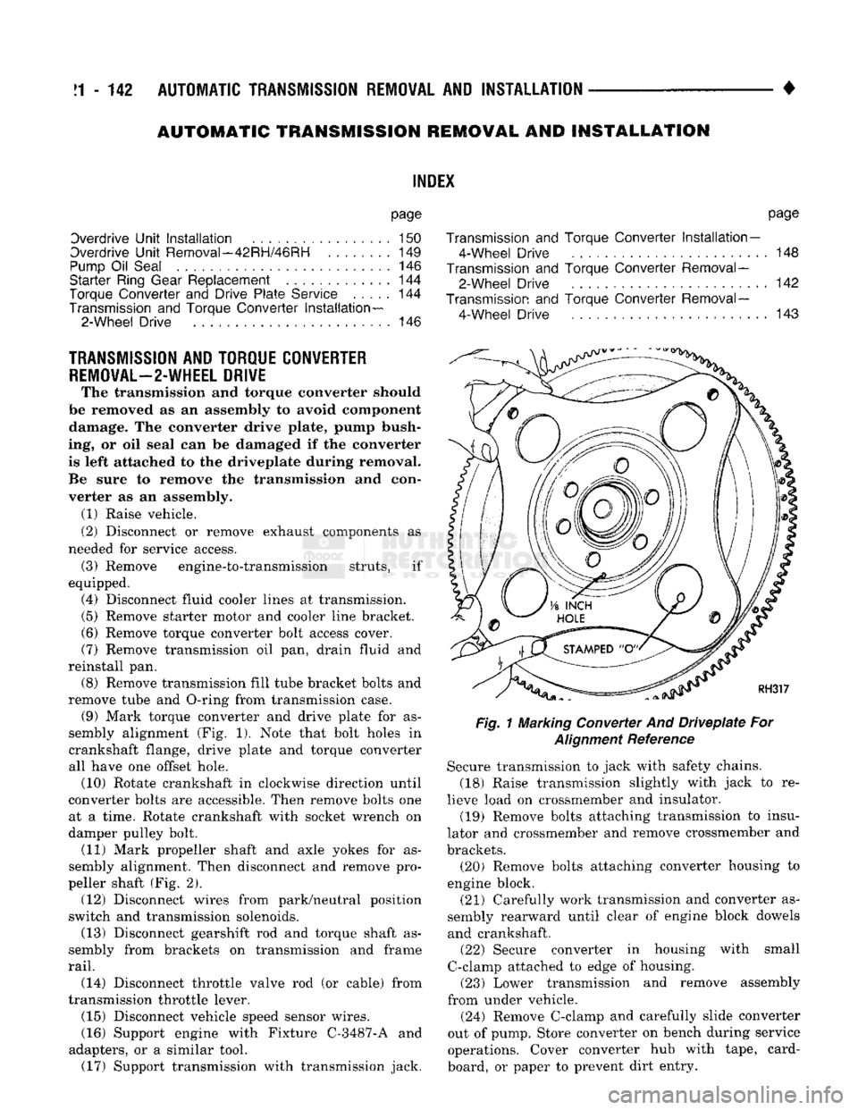
remove tube and O-ring from transmission case. (9) Mark torque converter and drive plate for as
sembly alignment (Fig. 1). Note that bolt holes in
crankshaft flange, drive plate and torque converter
all have one offset hole. (10) Rotate crankshaft in clockwise direction until
converter bolts are accessible. Then remove bolts one at a time. Rotate crankshaft with socket wrench on
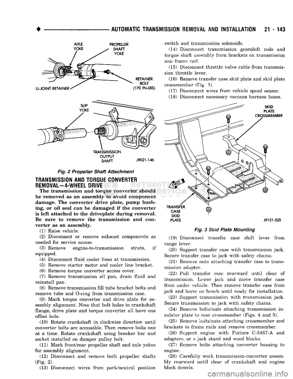
damper pulley bolt. (11) Mark propeller shaft and axle yokes for as
sembly alignment. Then disconnect and remove pro
peller shaft (Fig. 2). (12) Disconnect wires from park/neutral position
switch and transmission solenoids. (13) Disconnect gearshift rod and torque shaft as
sembly from brackets on transmission and frame
rail.
(14) Disconnect throttle valve rod (or cable) from
transmission throttle lever. (15) Disconnect vehicle speed sensor wires.
(16) Support engine with Fixture C-3487-A and
adapters, or a similar tool. (17) Support transmission with transmission jack.
Fig.
1 Marking Converter And
Driveplate
For
Alignment
Reference Secure transmission to jack with safety chains.
(18) Raise transmission slightly with jack to re
lieve load on crossmember and insulator. (19) Remove bolts attaching transmission to insu
lator and crossmember and remove crossmember and
brackets. (20) Remove bolts attaching converter housing to
engine block.
(21) Carefully work transmission and converter as
sembly rearward until clear of engine block dowels and crankshaft. (22) Secure converter in housing with small
C-clamp attached to edge of housing. (23) Lower transmission and remove assembly
from under vehicle.
(24) Remove C-clamp and carefully slide converter
out of pump. Store converter on bench during service
operations. Cover converter hub with tape, card
board, or paper to prevent dirt entry.
Page 1144 of 1502
•
AUTOMATIC TRANSMISSION REMOVAL
AND
INSTALLATION
21 - 143
AXLE
YOKE PROPELLER
SHAFT
YOKE
U-JOINT
RETAINER RETAINER
BOLT
(170
IN-LBS)
TRANSMISSION
OUTPUT
SHAFT
J9021-146
Fig.
2 Propeller Shaft Attachment
TRANSMISSION
AND TORQUE CONVERTER
REMOVAL—4-WHEEL
DRIVE
The transmission and torque converter should
be removed as an assembly to avoid component damage. The converter drive plate, pump bush
ing, or oil seal can be damaged if the converter
is left attached to the driveplate during removal.
Be sure to remove the transmission and con
verter as an assembly. (1) Raise vehicle.
(2) Disconnect or remove exhaust components as
needed for service access. (3) Remove engine-to-transmission struts, if
equipped. (4) Disconnect fluid cooler lines at transmission. (5) Remove starter motor and cooler line bracket.
(6) Remove torque converter access cover.
(7) Remove transmission oil pan, drain fluid and
reinstall pan. (8) Remove transmission fill tube bracket bolts and
remove tube and O-ring from transmission case. (9) Mark torque converter and drive plate for as
sembly alignment. Note that bolt holes in crankshaft
flange, drive plate and torque converter all have one
offset hole. (10) Rotate crankshaft in clockwise direction until
converter bolts are accessible. Then remove bolts one at a time. Rotate crankshaft using breaker bar and
socket installed on damper pulley bolt. (11) Mark front/rear propeller shaft and axle yokes
for assembly alignment. (12) Disconnect and remove both propeller shafts
(Fig. 2). (13) Disconnect wires from park/neutral position switch and transmission solenoids.
(14)
Disconnect transmission gearshift rods and
torque shaft assembly from brackets on transmission and frame rail.
(15) Disconnect throttle valve cable from transmis
sion throttle lever.
(16) Remove transfer case skid plate and skid plate
crossmember (Fig. 3). (17) Disconnect wires from vehicle speed sensor.
(18) Disconnect necessary vacuum harness hoses.
SKID
PLATE
CROSSMEMBER
TRANSFER
CASE
SKID
PLATE
J9121-525
Fig.
3
Skid
Plate
Mounting
(19) Disconnect transfer case shift lever from
range lever.
(20) Support transfer case with transmission jack.
Secure transfer case to jack with safety chains.
(21) Remove nuts attaching transfer case to trans
mission adapter.
(22) Pull transfer case rearward until clear of
transmission. Lower jack and move transfer case
from under vehicle. Then remove transfer case from
jack and leave on bench until ready for installation.
(23) Support transmission with transmission jack.
Secure transmission to jack with safety chains.
(24) Remove bolts/nuts attaching transmission in
sulator plate to rear crossmember (Figs. 4 and 5).
(25) Remove bolts/nuts attaching crossmember and
brackets to frame rails and remove crossmember.
(26) Support engine with Fixture C-3487-A and
adapters, or a jack stand and wood blocks.
(27) Remove bolts attaching converter housing to
engine. (28) Carefully work transmission-converter assem
bly rearward until clear of crankshaft and engine
block dowels.
Page 1150 of 1502
•
AUTOMATIC
TRANSMISSION
REMOVAL
AND
INSTALLATION
21 - 149
10).
Surface of converter lugs should be approxi
mately 13 mm (1/2 in.) to rear of straight edge when converter is fully seated.
(5) Temporarily secure converter in pump and
housing with C-clamp attached to housing edge, or
with metal strap attached across converter housing.
(6) Position transmission on jack. Secure transmis
sion to jack with safety chains.
(7) Check condition of converter driveplate. Re
place plate if cracked, distorted or damaged. If driveplate replacement was necessary, be sure
transmission dowel pins are seated in engine block and protrude far enough to held transmis sion in alignment.
(8) Coat pilot hub of torque converter with trans
mission fluid.
(9) Raise transmission and align converter with
drive plate and crankshaft.
(10) Move transmission forward. Then raise, lower
or tilt transmission to align converter housing with
dowels on engine block.
(11) Rotate converter to align marks scribed on
converter and driveplate. Offset holes in plate are
next to 1/8 in. hole in inner circle of plate (Fig. 1).
(12) Carefully work transmission forward and over
engine block dowels until converter hub is seated in crankshaft.
(13) Install bolts attaching converter housing to
engine.
(14) Install crossmember.
(15) Lower transmission onto crossmember and in
stall bolts attaching transmission and insulator to
crossmember (Figs. 4 and 5). (16) Remove fixture used to support engine.
(17) Connect vehicle speed sensor wires. (18) Install new plastic retainer grommet on any
shift linkage rod or lever that was disconnected. Old
grommets should not be reused. Use pry tool to re
move rod from grommet and cut away old grommet.
Use pliers to snap new grommet into lever and to snap rod into grommet. (19) Connect gearshift and throttle linkage to
transmission. (20) Connect wires to park/neutral position switch,
transmission solenoids and to oxygen sensor. Be sure
transmission harnesses are properly routed.
CAUTION:
It is essential
that
correct length
bolts
be
used
to
attach
the
converter
to the
driveplate.
Bolts
that
are too long
will
damage
the
clutch
surface
in
the converter. If new
bolts
are required, use the
bolts
specified in this procedure and in the parts
book
only.
(21) Verify converter bolt length. Bolt measure
ment is from bottom (underside) of bolt head to end
of bolt threads. • On 9.5 in., 3-lug converter, bolts should be 11.7
mm (0.46 in.) long.
• On 9.5 in., 4-lug converter, bolts should be 13.2
mm (0.52 in.) long.
• On 10.0 in., 4-lug converter, bolts should be 13.2
mm (0.52 in.) long.
• On 10.75 in., 4-lug converter, bolts should be 11.2
mm (0.44 in.) long.
(22) Install torque converter bolts. Tighten bolts as
follows:
• On models with 9.5 in., 3-lug converter, tighten
bolts to 54 Nnn (40 ft. lbs.).
• On models with 9.5 in., 4-lug converter, tighten
bolts to 74 Nnn (55 ft. lbs.).
• On models with 10.0 in., 4-lug converter, tighten
bolts to 74 Nnn (55 ft. lbs.) torque.
• On models with 10.75 in., 4-lug converter, tighten
bolts to 31 Nnn (270 in. lbs.).
• On diesel models with 12.2 in. converter, tighten
bolts to 47 Nnn (35 ft. lbs.) torque.
(23) Install converter housing access cover. (24) Install starter motor and cooler line bracket.
(25) Connect cooler lines to transmission.
(26) Install transmission fill tube. Install new
O-ring seal on tube before installation.
(27) Install any exhaust components removed for
service access. (28) Support transfer case on transmission jack.
Secure transfer case to jack with safety chains. (29) Install gasket on transmission adapter. Coat
gasket with Mopar perfect, seal, or silicone sealer be
forehand. (30) Install transfer case on transmission. Tighten
transfer case attaching nuts to 47 Nnn (35 ft. lbs.) torque. (31) Remove jack supporting transfer case.
(32) Connect transfer case shift lever to range le
ver. (33) Align and install propeller shafts. Tighten
clamp bolts to 19 Nnn 170 in. lbs.) torque. (34) Install transfer case skid plate and crossmem
ber. (35) Lower vehicle.
(36) Fill transmission with Mopar ATF Plus, Type
7176, or Mopar Dexron II if ATF Plus is not readily
available. (37) Check and adjust gearshift, throttle valve and
transfer case shift linkages if necessary.
OVERDRIVE
UNIT
REMOVAL—42RH/46RH
The following removal and installation procedures
apply to the 42RH/46RH overdrive unit only. If the
complete transmission assembly must be removed,
refer to the Transmission And Converter Removal and Installation procedures. (1) Shift transmission into Park.
(2) Raise vehicle.