1993 DODGE TRUCK compression ratio
[x] Cancel search: compression ratioPage 94 of 1502
•
FRONT
SUSPENSION
AND
AXLE
2 - 41
SPECIAL
TOOL
D-145
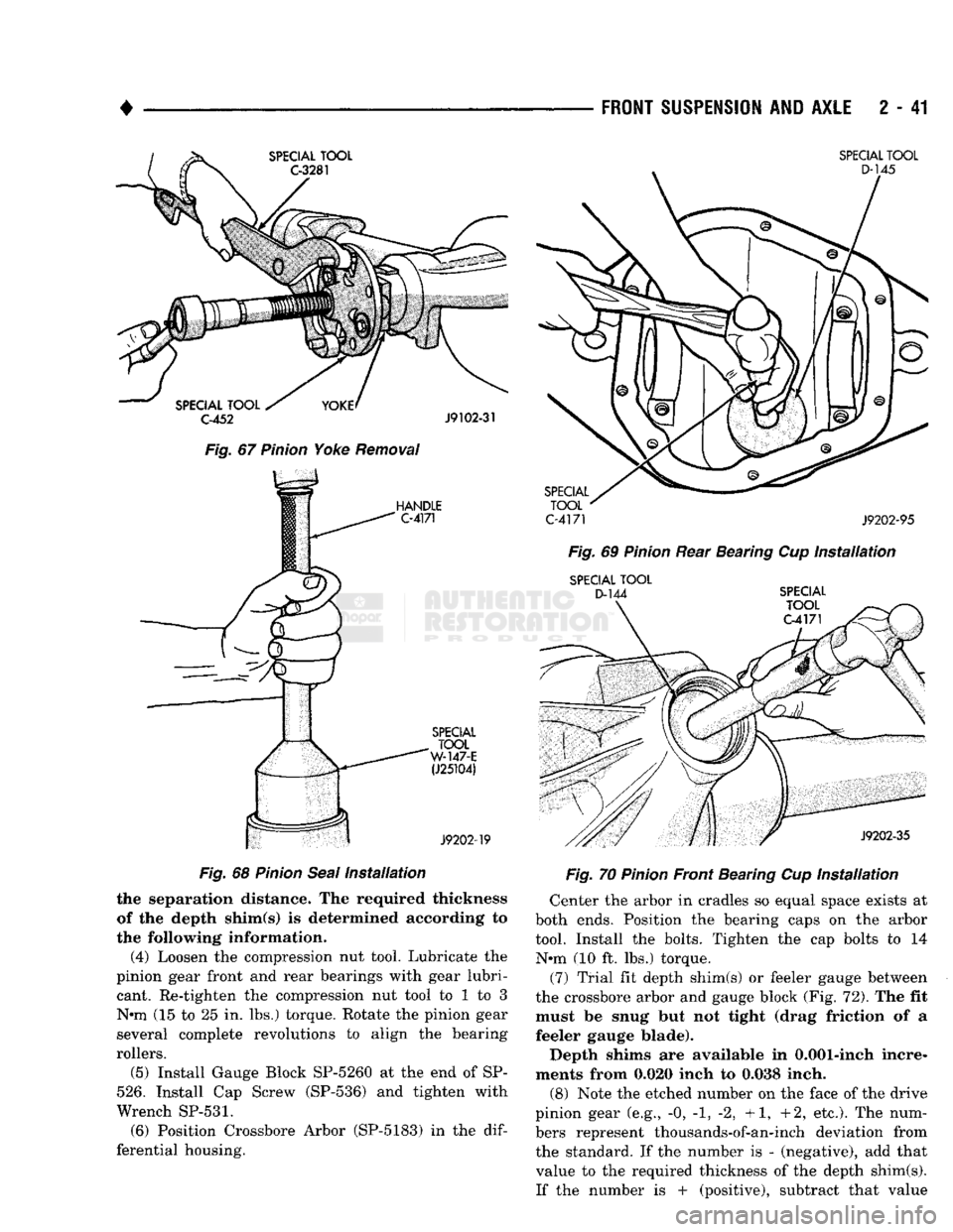
Fig.
67
Pinion
Yoke
Removal
HANDLE
C-4171
SPECIAL
TOOL
C-4171
J9202-95 Fig.
69
Pinion
Rear Bearing Cup
Installation
SPECIAL
TOOL
D-144
SPECIAL
TOOL
C-4171
SPECIAL
TOOL
W-147-E
(J25104)
J9202-19
Fig.
68
Pinion
Seal
Installation
the separation distance. The required thickness
of the depth shim(s) is determined according to
the following information.
(4) Loosen the compression nut tool. Lubricate the
pinion gear front and rear bearings with gear lubri cant. Re-tighten the compression nut tool to 1 to 3
N«m (15 to 25 in. lbs.) torque. Rotate the pinion gear
several complete revolutions to align the bearing
rollers.
(5) Install Gauge Block SP-5260 at the end of SP-
526.
Install Cap Screw (SP-536) and tighten with
Wrench
SP-531.
(6) Position Crossbore Arbor (SP-5183) in the
dif
ferential housing.
J9202-35
Fig.
70
Pinion
Front Bearing Cup
Installation
Center the arbor in cradles so equal space exists at
both ends. Position the bearing caps on the arbor
tool. Install the bolts. Tighten the cap bolts to 14 N*m (10 ft. lbs.) torque.
(7) Trial fit depth shim(s) or feeler gauge between
the crossbore arbor and gauge block (Fig. 72). The fit must be snug but not tight (drag friction of a
feeler gauge blade).
Depth shims are available in 0.001-inch incre
ments from 0.020 inch to 0.038 inch.
(8) Note the etched number on the face of the drive
pinion gear (e.g., -0, -1, -2, +1, +2, etc.). The num
bers represent thousands-of-an-inch deviation from
the standard. If the number is - (negative), add that value to the required thickness of the depth shim(s).
If the number is + (positive), subtract that value
Page 122 of 1502
•
.
C-4171 J9203-65
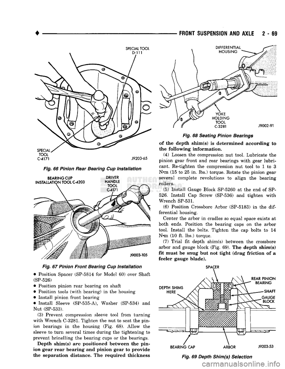
Fig.
66
Pinion
Rear Bearing Cup
Installation
BEARING
CUP DRIVER
INSTALLATION
TOOL
C-4203
HANDLE
Fig.
67
Pinion
Front Bearing Cup
Installation
•
Position Spacer (SP-5814 for Model 60) over Shaft
(SP-526)
•
Position pinion rear bearing on shaft
•
Position tools (with bearing) in the housing
•
Install pinion front bearing
•
Install Sleeve
(SP-535-A),
Washer (SP-534) and
Nut
(SP-533).
(3) Prevent compression sleeve tool from turning
with Wrench C-3281. Tighten the nut to seat the pin ion bearings in the housing (Fig. 68). Allow the
sleeve to turn several times during the tightening to
prevent brinelling the bearing cups or the bearings.
Depth shim(s) are positioned between the pin
ion gear rear bearing and pinion gear to provide
the separation distance. The required thickness
FRONT SUSPENSION
AND
AXLE
2 - 69
Fig.
68 Seating
Pinion
Bearings
of the depth shim(s) is determined according to
the following information.
(4) Loosen the compression nut tool. Lubricate the
pinion gear front and rear bearings with gear lubri cant. Re-tighten the compression nut tool to 1 to 3
Nnn (15 to 25 in. lbs.) torque. Rotate the pinion gear several complete revolutions to align the bearing
rollers.
(5) Install Gauge Block SP-5260 at the end of SP-
526.
Install Cap Screw (SP-536) and tighten with
Wrench
SP-531.
(6) Position Crossbore Arbor (SP-5183) in the
dif
ferential housing.
Center the arbor in cradles so equal space exists at
both ends. Position the bearing caps on the arbor
tool. Install the bolts. Tighten the cap bolts to 14 Nnn (10 ft. lbs.) torque.
(7) Trial fit depth shim(s) between the crossbore
arbor and gauge block (Fig. 69). The depth shim(s)
fit must be snug but not tight (drag friction of a
feeler gauge blade).
SPACER
BEARING CAP ARBOR
J9203-53
Fig.
69 Depth
Shim(s)
Selection
SPECIAL
TOOL
Page 147 of 1502
3
- 20
REAR SUSPENSION
AND
AXLE
•
SPECIAL
TOOL
C-4171
SPECIAL
TOOL
8-3/8-
C-4340
9.1/4-
C-4213
J9203-33
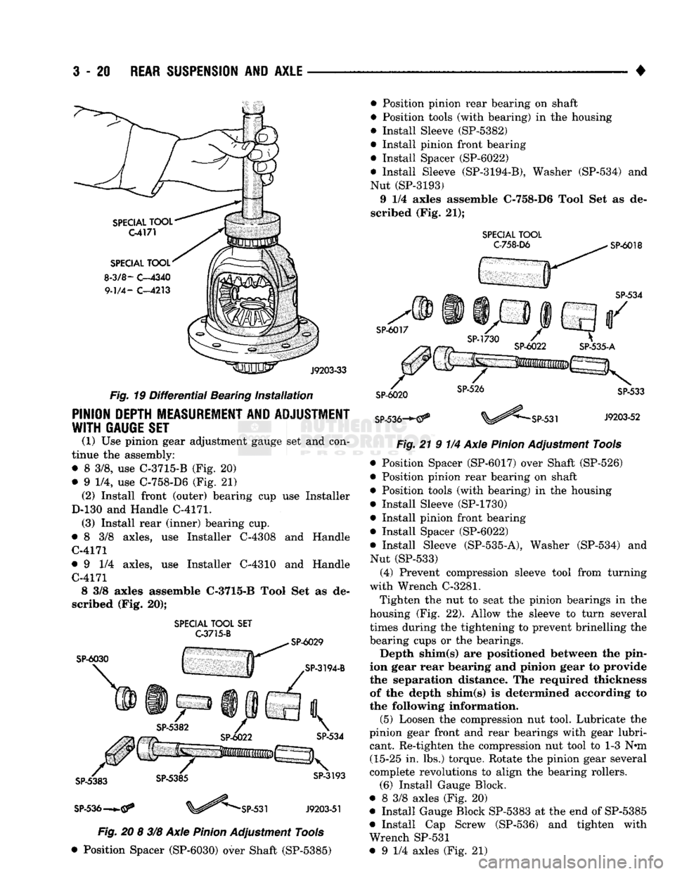
Fig.
19 Differential Bearing Installation
PINION DEPTH MEASUREMENT AND ADJUSTMENT
WITH
GAUGE SET
(1) Use pinion gear adjustment gauge set and con
tinue the assembly: • 8 3/8, use C-3715-B (Fig. 20)
• 9 1/4, use C-758-D6 (Fig. 21) (2) Install front (outer) bearing cup use Installer
D-130 and Handle C-4171. (3) Install rear (inner) bearing cup.
• 8 3/8 axles, use Installer C-4308 and Handle C-4171
• 9 1/4 axles, use Installer C-4310 and Handle C-4171 8 3/8 axles assemble C-3715-B Tool Set as de
scribed (Fig. 20);
SPECIAL
TOOL
SET
G3715-B
SP-6030
SP-536—
SP-531
J9203-51
Fig.
20 8 3/8 Axle
Pinion
Adjustment Tools
• Position Spacer (SP-6030) over Shaft (SP-5385) • Position pinion rear bearing on shaft
• Position tools (with bearing) in the housing
• Install Sleeve (SP-5382)
• Install pinion front bearing
• Install Spacer (SP-6022)
• Install Sleeve (SP-3194-B), Washer (SP-534) and
Nut (SP-3193) 9 1/4 axles assemble C-758-D6 Tool Set as de
scribed (Fig. 21);
SPECIAL TOOL C-758-D6
SP-6018
SP-536-*-
21 9 1/4 Axle
Pinion
Adjustment Tools and • Position Spacer (SP-6017) over Shaft (SP-526)
• Position pinion rear bearing on shaft
• Position tools (with bearing) in the housing
• Install Sleeve (SP-1730)
• Install pinion front bearing
• Install Spacer (SP-6022)
• Install Sleeve (SP-535-A), Washer (SP-534)
Nut (SP-533) (4) Prevent compression sleeve tool from turning
with Wrench C-3281.
Tighten the nut to seat the pinion bearings in the
housing (Fig. 22). Allow the sleeve to turn several
times during the tightening to prevent brinelling the
bearing cups or the bearings.
Depth shim(s) are positioned between the pin
ion gear rear bearing and pinion gear to provide the separation distance. The required thickness
of the depth shim(s) is determined according to
the following information. (5) Loosen the compression nut tool. Lubricate the
pinion gear front and rear bearings with gear lubri cant. Re-tighten the compression nut tool to 1-3 N*m (15-25 in. lbs.) torque. Rotate the pinion gear several
complete revolutions to align the bearing rollers. (6) Install Gauge Block.
• 8 3/8 axles (Fig. 20)
• Install Gauge Block SP-5383 at the end of SP-5385
• Install Cap Screw (SP-536) and tighten with
Wrench SP-531 • 9 1/4 axles (Fig. 21)
Page 171 of 1502
3
- 44
REAR SUSPENSION
AND
AXLE
— __—_ . _ •
SPECIAL
TOOL
SET
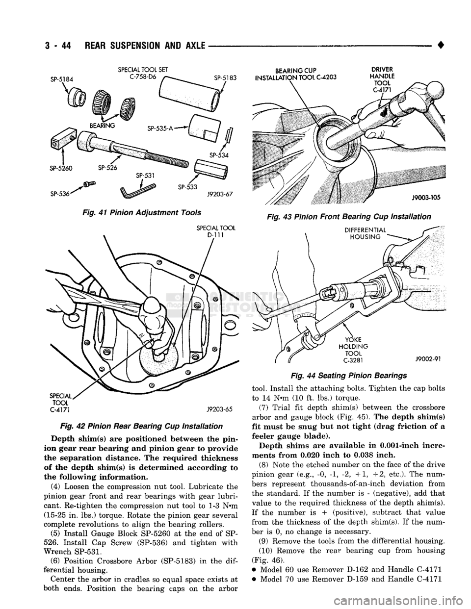
Fig.
41
Pinion
Adjustment Tools
SPECIAL
TOOL
C-4171
J9203-65
Fig.
42
Pinion
Rear Bearing Cup
Installation
Depth shim(s) are positioned between the pin
ion gear rear bearing and pinion gear to provide
the separation distance. The required thickness of the depth shim(s) is determined according to
the following information.
(4) Loosen the compression nut tool. Lubricate the
pinion gear front and rear bearings with gear lubri cant. Re-tighten the compression nut tool to 1-3 N-m (15-25 in. lbs.) torque. Rotate the pinion gear several
complete revolutions to align the bearing rollers.
(5) Install Gauge Block SP-5260 at the end of SP-
526.
Install Cap Screw (SP-536) and tighten with
Wrench
SP-531.
(6) Position Crossbore Arbor (SP-5183) in the
dif
ferential housing. Center the arbor in cradles so equal space exists at
both ends. Position the bearing caps on the arbor
BEARING
CUP DRIVER
INSTALLATION
TOOL
C-4203
HANDLE
Fig.
44 Seating
Pinion
Bearings
tool. Install the attaching bolts. Tighten the cap bolts
to 14 N-m (10 ft. lbs.) torque.
(7) Trial fit depth shim(s) between the crossbore
arbor and gauge block (Fig. 45). The depth shim(s)
fit must be snug but not tight (drag friction of a
feeler gauge blade).
Depth shims are available in 0.001-inch incre
ments from 0.020 inch to 0.038 inch.
(8) Note the etched number on the face of the drive
pinion gear (e.g., -0, -1, -2, +1, +2, etc.). The num
bers represent thousands-of-an-inch deviation from the standard. If the number is - (negative), add that
value to the required thickness of the depth shim(s).
If the number is + (positive), subtract that value
from the thickness of the depth shim(s). If the num
ber is 0, no change is necessary.
(9) Remove the tools from the differential housing.
(10) Remove the rear bearing cup from housing
(Fig. 46),
* Model 60 use Remover D-162 and Handle C-4171 *> Model 70 use Remover D-159 and Handle C-4171
Page 611 of 1502

9
- 6
ENGINES
•
SERVICE DIAGNOSIS (GASOLINE ENGINES)
•
PERFORMANCE (CONT.)
1
CONDITION
POSSIBLE
CAUSES
^
CORRECTION
1
ENGINE
LOSS
OF
POWER
1.
Incorrect ignition timing.
2. Worn or burned distributor
rotor.
3. Worn distributor shaft.
4.
Dirty
or
incorrectly
gapped
spark
plugs.
5.
Dirt
or
water
in
fuel
system.
6.
Faulty
fuel
pump.
7.
Incorrect valve timing.
8.
Blown
cylinder head
gasket.
9.
Low
compression.
10.
Burned,
warped or
pitted
valves.
11.
Plugged
or
restricted
exhaust
system.
12. Faulty ignition
cables.
13. Faulty coil.
1.
Refer
to
Group
8D, Ignition
System.
2. install new distributor
rotor.
3.
Remove
and
repair
distributor
(refer
to
Group
8D, Ignition
System).
4.
Clean
plugs
and
set gap
(refer
to
Group
8D, Ignition
System).
5. Clean
system
and replace
fuel
filter.
6. Install new
fuel
pump.
7.
Correct
valve
timing.
8. Install new cylinder head
gasket.
9.
Test
compression
of
each
cylinder.
10.
Install new
valves.
11.
Install new
parts,
as
necessary.
12.
Replace
any cracked or
shorted
cables.
13.
Test
and
replace,
as
necessary
(refer
to
Group
8D, Ignition
System).
ENGINE
MISSES
ON
ACCELERATION
1.
Dirty
or
gap set
too
wide
in spark
plug.
2. Incorrect ignition timing.
3.
Dirt
in
fuel
system.
4.
Burned,
warped or
pitted
valves.
5. Faulty coil.
1.
Clean spark
plugs
and set gap
(refer
to
Group
8D, Ignition
System).
2. Refer to
Group
8D, Ignition
System.
3. Clean
fuel
system.
4.
Install new
valves.
5.
Test
and
replace,
if
necessary,
(refer
to
Group
8D, Ignition
System).
ENGINE
MISSES
AT HIGH
SPEED
1.
Dirty
or
gap set too
wide
in spark
plug.
2. Worn distributor shaft.
3. Worn or burned distributor
rotor.
4. Faulty
coil.
5. Incorrect ignition timing.
6.
Dirty
injector
in
throttle
body.
7.
Dirt
or
water
in
fuel
system.
1.
Clean
spark
plugs
and
set gap
(refer
to
Group
8D, Ignition
System).
2.
Remove
and
repair
distributor
(refer
to
Group
8D,
Ignition
System).
3. Install new distributor
rotor.
4.
Test
and replace,
as
necessary
(refer
to
Group
8D, Ignition
System).
5.
Refer
to
Group
8D, Ignition
System.
6.
Clean
injector.
7.
Clean
system
and replace
fuel
filter.
J9309-106
Page 617 of 1502
9
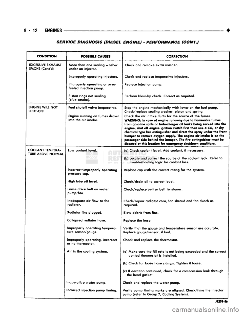
- 12
ENGINES
•
CONDITION
POSSIBLE
CAUSES
CORRECTION
EXCESSIVE
EXHAUST
SMOKE
(Cont'd)
More
than
one
sealing washer
under an injector.
Check
and remove
extra
washer.
Improperly operating injectors.
Check
and replace inoperative injectors.
Improperly operating or over-
fueled injection pump.
Replace
injection pump.
Piston
rings
not sealing
(blue smoke). Perform blow-by check. Correct as required.
ENGINE
WILL
NOT
SHUT-OFF
Fuel shutoff valve inoperative.
Engine
running on fumes drawn into the air intake.
Stop
the engine mechanically
with
lever on the
fuel
pump.
Check/replace
sealing washer, piston and
spring.
Check
the air intake ducts for the source of the fumes.
WARNING:
In
ease
of engine runaway due to flammable
fumes
from gasoline spills or turbocharger oil leaks
being
sucked
into the
engine,
shut off engine ignition switch first then use a CO* or dry
chemical type
fire
extinguisher
and direct the
spray
under
the
front
bumper to
remove
oxygen
supply. The engine air
intake
is on the
passenger
side
behind the bumper. The
fire
extinguisher
must
bo
directed at this location for emergency shutdown conditions.
COOLANT
TEMPERA
TURE
ABOVE
NORMAL
Low
coolant level.
(a) Check coolant level. Add coolant, if necessary.
(b) Locate and correct the source of the coolant leak. Refer to
troubleshooting
logic for coolant
loss.
Incorrect/improperly operating
pressure
cap.
Replace
cap
with
the correct rating for the
system.
High
lube oil level.
Check/drain
oil to correct level.
Loose
drive belt on water
pump/fan.
Check/replace
belt or belt tensioner.
Inadequate air flow to the radiator. Check/repair radiator core, fan shroud and fan clutch as
required.
Radiator
fins
plugged.
Blow
debris from fins.
Collapsed
radiator
hose.
Replace
the
hose.
Improperly operating tempera
ture
sensor/gauge.
Verify
that
the
gauge
and temperature
sensor
are accurate.
Replace
gauge/sensor,
if bad.
Improperly operating, incorrect
or
no thermostat.
Check
and replace the thermostat.
Air
in the cooling
system.
(a) Make sure the
fill
rate
is not being exceeded and the correct
vented thermostat is installed.
(b) Check for loose hose
clamps.
Tighten if
loose.
(c) If aeration continued, check for a
compression
leak through the head gasket.
Inoperative water pump.
Check
and replace the water pump.
incorrect injection pump timing. Verify pump timing marks are aligned. Check/time the injector
pump
(refer
to Group 7,
Cooling
System).
J9209-56
SERVICE DIAGNOSIS (DIESEL ENGINE) - PERFORMANCE (CONT.)
Page 622 of 1502
•
3.9L ENGINE
9 - 17
3.9L
ENGINE SERVICE PROCEDURES
INDEX
page
Camshaft
31
Crankshaft
38
Crankshaft Main Bearings
39
Crankshaft Rear
Oil
Seals
. 40
Cylinder Block
41
Cylinder Head Cover
. , 21
Cylinder Heads
. 22
Distributor
33
Engine
Assembly .........................
20
Engine
Front Mounts
17
Engine
Rear Mount
18
Front Crankshaft
Oil
Seal Replacement ........
31
GENERAL INFORMATION
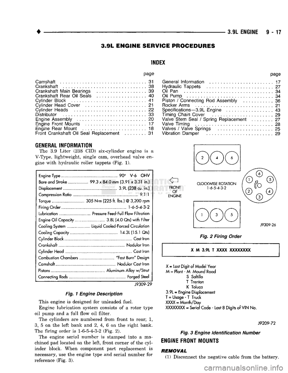
The 3.9 Liter (238 CID) six-cylinder engine is a
V-Type, lightweight, single cam, overhead valve en gine with hydraulic roller tappets (Fig. 1).
Engine
Type
90° V-6 OHV
Bore
and Stroke 99.3
x
84.0 mm (3.91 x3.31
in.)
Displacement 3.9L (238 cu.
in.)
Compression
Ratio
9.1:1
Torque 305 N-m (225
ft.
lbs.)
@
3,200
rpm
Firing Order.... 1-6-5-4-3-2
Lubrication
Pressure
Feed-Full Flow
Filtration
Engine
Oil
Capacity 3.8L (4.0 Qts)
with Filter
Cooling
System
Liquid Cooled-Forced
Circulation
Cooling Capacity 14.3L
(15.1
Qts)
Cylinder Block Cast Iron
Crankshaft Nodular Iron
Cylinder Head
Cast
Iron
Combustion Chambers "Fast
Burn"
Design
Camshaft Nodular
Cast
Iron
Pistons
Aluminum Alloy
w/Strut
Connecting
Rods
Forged Steel
J9309-29
Fig.
1
Engine
Description
This engine is designed for unleaded fuel. Engine lubrication system consists of a rotor type
oil pump and a full flow oil filter.
The cylinders are numbered from front to rear; 1,
3,
5 on the left bank and 2, 4, 6 on the right bank.
The firing order is
1-6-5-4-3-2
(Fig. 2).
The engine serial number is stamped into a ma
chined pad located on the left, front corner of the cyl
inder block. When component part replacement is
necessary, use the engine type and serial number for
reference (Fig. 3).
page
General
Information
17
Hydraulic Tappets
27
Oil
Pan 34
Oil Pump
34
Piston
/
Connecting
Rod
Assembly
36
Rocker
Arms
21
Specifications—3.9L Engine
43
Timing Chain Cover
29
Valve Stem Seal
/
Spring Replacement ........
27
Valve Timing
28
Valves
/
Valve Springs
25
Vibration
Damper
29
J9309-26
Fig.
2 Firing Order i M 3.9L T xxxx
XXXXXXXX
X
=
Last Digit
of
Model Year
M
=
Plant -
M
Mound
Road
S
Sabillo
T Trenton
K
Toluca
3.9L
=
Engine Displacement
T
=
Usage
-
T Truck
XXXX
=
Month/Day
XXXXXXXX
- Serial Code -
Last
8
Digits of
VIN
No.
J9209-72
Fig.
3
Engine
identification
Number
ENGINE FRONT MOUNTS
REMOVAL (1) Disconnect the negative cable from the battery.
Page 632 of 1502
•
3.9L
ENGINE
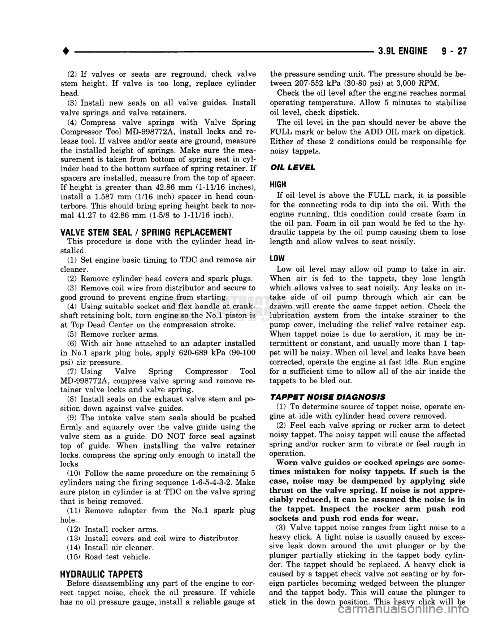
9 - 27 (2) If valves or seats are reground, check valve
stem height. If valve is too long, replace cylinder
head.
(3) Install new seals on all valve guides. Install
valve springs and valve retainers.
(4) Compress valve springs with Valve Spring
Compressor Tool MD-998772A, install locks and re
lease tool. If valves and/or seats are ground, measure
the installed height of springs. Make sure the mea surement is taken from bottom of spring seat in cyl
inder head to the bottom surface of spring retainer. If
spacers are installed, measure from the top of spacer.
If height is greater than 42.86 mm (1-11/16 inches), install a 1.587 mm (1/16 inch) spacer in head coun-
terbore. This should bring spring height back to nor
mal 41.27 to 42.86 mm (1-5/8 to
1-11/16
inch).
VALVE STEM SEAL
/
SPRING REPLACEMENT
This procedure is done with the cylinder head in
stalled. (1) Set engine basic timing to TDC and remove air
cleaner. (2) Remove cylinder head covers and spark plugs.
(3) Remove coil wire from distributor and secure to
good ground to prevent engine from starting. (4) Using suitable socket and flex handle at crank
shaft retaining bolt, turn engine so the No.l piston is
at Top Dead Center on the compression stroke. (5) Remove rocker arms.
(6) With air hose attached to an adapter installed
in No.l spark plug hole, apply 620-689 kPa (90-100
psi) air pressure. (7) Using Valve Spring Compressor Tool
MD-998772A, compress valve spring and remove re
tainer valve locks and valve spring. (8) Install seals on the exhaust valve stem and po
sition down against valve guides. (9) The intake valve stem seals should be pushed
firmly and squarely over the valve guide using the valve stem as a guide. DO NOT force seal against
top of guide. When installing the valve retainer
locks,
compress the spring only enough to install the
locks.
(10) Follow the same procedure on the remaining 5
cylinders using the firing sequence
1-6-5-4-3-2.
Make sure piston in cylinder is at TDC on the valve spring
that is being removed. (11) Remove adapter from the No.l spark plug
hole.
(12) Install rocker arms.
(13) Install covers and coil wire to distributor.
(14) Install air cleaner.
(15) Road test vehicle.
HYDRAULIC
TAPPETS
Before disassembling any part of the engine to cor
rect tappet noise, check the oil pressure. If vehicle
has no oil pressure gauge, install a reliable gauge at the pressure sending unit. The pressure should be be
tween 207-552 kPa (30-80 psi) at 3,000 RPM.
Check the oil level after the engine reaches normal
operating temperature. Allow 5 minutes to stabilize
oil level, check dipstick.
The oil level in the pan should never be above the
FULL mark or below the ADD OIL mark on dipstick.
Either of these 2 conditions could be responsible for
noisy tappets.
OIL
LEWEL
HIGH
If oil level is above the FULL mark, it is possible
for the connecting rods to dip into the oil. With the engine running, this condition could create foam in
the oil pan. Foam in oil pan would be fed to the hy draulic tappets by the oil pump causing them to lose
length and allow valves to seat noisily.
LOW
Low oil level may allow oil pump to take in air.
When air is fed to the tappets, they lose length
which allows valves to seat noisily. Any leaks on in
take side of oil pump through which air can be drawn will create the same tappet action. Check the
lubrication system from the intake strainer to the
pump cover, including the relief valve retainer cap.
When tappet noise is due to aeration, it may be in
termittent or constant, and usually more than 1 tap
pet will be noisy. When oil level and leaks have been corrected, operate the engine at fast idle. Run engine
for a sufficient time to allow all of the air inside the
tappets to be bled out.
TAPPET
NOISE DIAGNOSIS
(1) To determine source of tappet noise, operate en
gine at idle with cylinder head covers removed. (2) Feel each valve spring or rocker arm to detect
noisy tappet. The noisy tappet will cause the affected
spring and/or rocker arm to vibrate or feel rough in
operation.
Worn valve guides or cocked springs are some
times mistaken for noisy tappets. If such is the
case, noise may be dampened by applying side
thrust on the valve spring. If noise is not appre ciably reduced, it can be assumed the noise is in
the tappet. Inspect the rocker arm push rod sockets and push rod ends for wear.
(3) Valve tappet noise ranges from light noise to a
heavy click. A light noise is usually caused by exces sive leak down around the unit plunger or by the
plunger partially sticking in the tappet body cylin der. The tappet should be replaced. A heavy click is
caused by a tappet check valve not seating or by for
eign particles becoming wedged between the plunger
and the tappet body. This will cause the plunger to
stick in the down position. This heavy click will be