1993 DODGE TRUCK compression ratio
[x] Cancel search: compression ratioPage 643 of 1502
9
- 38 3.9L
ENGINE
•
OIL
RING
SPACER
GAP
TOP
COMPRESSION
RING
GAP
SECOND
COMPRESSION
RING
GAP
OIL
RING
RAiL
GAP (TOP) OIL
RING
RAIL
GAP
(BOTTOM)
J9309-80
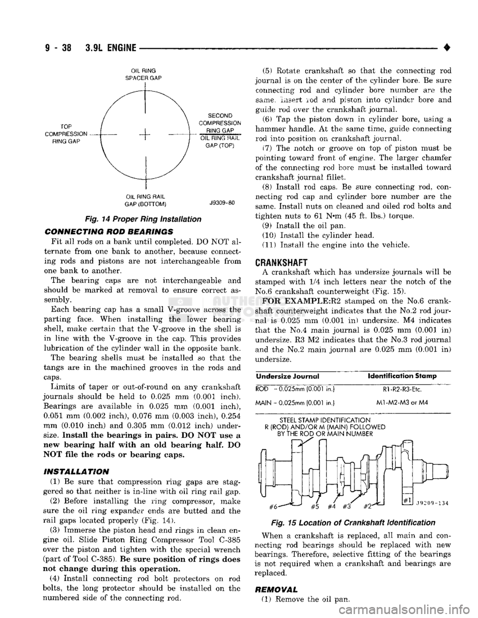
Fig.
14 Proper
Ring
Installation
CONNECTING ROD BEARINGS Fit all rods on a bank until completed. DO NOT al
ternate from one bank to another, because connect ing rods and pistons are not interchangeable from
one bank to another.
The bearing caps are not interchangeable and
should be marked at removal to ensure correct as sembly.
Each bearing cap has a small V-groove across the
parting face. When installing the lower bearing shell, make certain that the V-groove in the shell is
in line with the V-groove in the cap. This provides
lubrication of the cylinder wall in the opposite bank.
The bearing shells must be installed so that the
tangs are in the machined grooves in the rods and
caps.
Limits of taper or out-of-round on any crankshaft
journals should be held to 0.025 mm (0.001 inch). Bearings are available in 0.025 mm (0.001 inch), 0.051 mm (0.002 inch), 0.076 mm (0.003 inch), 0.254
mm (0.010 inch) and 0.305 mm (0.012 inch) under-
size.
Install the bearings in pairs. DO NOT use a
new bearing half with an old bearing
half.
DO
NOT file the rods or bearing caps.
INSTALLATION (1) Be sure that compression ring gaps are stag
gered so that neither is in-line with oil ring rail gap. (2) Before installing the ring compressor, make
sure the oil ring expander ends are butted and the
rail gaps located properly (Fig. 14).
(3) Immerse the piston head and rings in clean en
gine oil. Slide Piston Ring Compressor Tool C-385
over the piston and tighten with the special wrench (part of Tool C-385). Be sure position of rings does
not change during this operation.
(4) Install connecting rod bolt protectors on rod
bolts,
the long protector should be installed on the numbered side of the connecting rod. (5) Rotate crankshaft so that the connecting rod
journal is on the center of the cylinder bore. Be sure connecting rod and cylinder bore number are the
same. Insert rod and piston into cylinder bore and
guide rod over the crankshaft journal.
(6) Tap the piston down in cylinder bore, using a
hammer handle. At the same time, guide connecting
rod into position on crankshaft journal.
(7) The notch or groove on top of piston must be
pointing toward front of engine. The larger chamfer
of the connecting rod bore must be installed toward
crankshaft journal fillet.
(8) Install rod caps. Be sure connecting rod, con
necting rod cap and cylinder bore number are the same. Install nuts on cleaned and oiled rod bolts and
tighten nuts to 61 N»m (45 ft. lbs.) torque.
(9) Install the oil pan. (10) Install the cylinder head.
(11) Install the engine into the vehicle.
CRANKSHAFT
A crankshaft which has undersize journals will be
stamped with 1/4 inch letters near the notch of the
No.6 crankshaft counterweight (Fig. 15). FOR EXAMPLE:R2 stamped on the No.6 crank
shaft counterweight indicates that the No.2 rod jour
nal is 0.025 mm (0.001 in) undersize. M4 indicates
that the No.4 main journal is 0.025 mm (0.001 in) undersize. R3 M2 indicates that the No.3 rod journal
and the No.2 main journal are 0.025 mm (0.001 in) undersize.
Undersize
Journal Identification
Stamp
ROD
-
0.025mm
(0.001
in.)
Rl-R2-R3-Etc.
MAIN -
0.025mm
(0.001
in.)
M1-M2-M3
or M4
STEEL
STAMP
IDENTIFICATION
R
(ROD)
AND/OR
M
(MAIN)
FOLLOWED
BY THE ROD
OR
MAIN
NUMBER
Fig.
15 Location of Crankshaft
Identification
When a crankshaft is replaced, all main and con
necting rod bearings should be replaced with new
bearings. Therefore, selective fitting of the bearings is not required when a crankshaft and bearings are
replaced.
REMOVAL (1) Remove the oil pan.
Page 652 of 1502
5.2L
ENGINE
9 - 47
S.2L ENGINE
SERVICE
PROCEDURES
INDEX
page
Camshaft
. , . 61
Crankshaft
68
Crankshaft Main Bearings
69
Crankshaft Rear
Oil
Seals
...... ........
70
Cylinder Block ...........................
71
Cylinder Head Cover
. . . . 51
Cylinder Heads
52
Distributor
62
Engine
Assembly
. 50
Engine
Front Mounts
47
Engine
Rear Mount ...............
48
Front Crankshaft
Oil
Seal Replacement
. . 61
GENERAL
INFORMATION
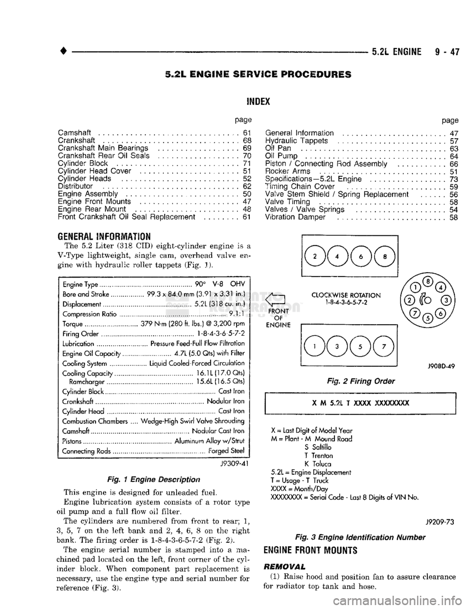
The 5.2 Liter (318 CID) eight-cylinder engine is a
V-Type lightweight, single cam, overhead valve en gine with hydraulic roller tappets (Fig. J).
Engine
Type ....
90° V-8 OHV
Bore
and Stroke .....
99.3
x
84.0 mm
(3.91
x
3.31
in.)
Displacement................
5.2L(318cu.
in.)
Compression
Ratio ....... .
9.1:1
Torque .. 379 N-m (280
ft.
lbs.)
@
3,200
rpm
Firing Order .... 1-8-4-3-6-5-7-2
Lubrication
.......
Pressure
Feed-Full Flow
Filtration
Engine
Oil
Capacity......
4.7L
(5.0 Qts)
with Filter
Cooling System ...... Liquid Cooled-Forced
Circulation
Cooling Capacity..........
16.1L(17.0Qts)
Ramcharger
15.6L
(16.5 Qts)
Cylinder Block
,
Cast
Iron
Crankshaft Nodular Iron
Cylinder Head ..............
Cast
Iron
Combustion Chambers
..
Wedge-High
Swirl Valve Shrouding
Camshaft Nodular Cast Iron
Pistons
Aluminum Alloy
w/Strut
Connecting
Rods...........
Forged
Steel
J9309-41
Fig. 1
Engine
Description
This engine is designed for unleaded fuel.
Engine lubrication system consists of a rotor type
oil pump and a full flow oil filter.
The cylinders are numbered from front to rear; 1?
3,
5, 7 on the left bank and 2, 4, 6, 8 on the right
bank. The firing order is 1-8-4-3-6-5-7-2 (Fig. 2).
The engine serial number is stamped into a ma
chined pad located on the left, front corner of the cyl
inder block. When component part replacement is
necessary, use the engine type and serial number for
reference (Fig. 3).
page
General
Information
.......................
47
Hydraulic Tappets
57
Oil
Pan . 63
Oil Pump
. 64
Piston
/
Connecting
Rod
Assembly
66
Rocker
Arms
51
Specifications—5.2L Engine
73
Timing Chain Cover ................
59
Valve Stem Shield
/
Spring Replacement
56
Valve Timing
. 58
Valves
/
Valve Springs
54
Vibration
Damper
. . 58
J908D-49
Fig.
2 Firing Order
X
M 5.2L T
XXXX
XXXXXXXX
X
~
Last Digit of
Model
Year
M
=
Plant
- M
Mound
Road
S
Saltillo
T
Trenton
K
Toluca
5.2L
=
Engine Displacement
T
=
Usage
-
T Truck
XXXX
=
Month/Day
XXXXXXXX
=
Serial Code
-
Last
8
Digits
of
VIN
No.
J9209-73
Fig.
3
Engine
Identification
Number
ENGINE
FRONT
MOUNTS
REMOVAL
(1) Raise hood and position fan to assure clearance
for radiator top tank and hose.
Page 673 of 1502
9
- 68 5.2L
ENGINE
• INSTALLATION
(1) Be sure that compression ring gaps are stag
gered so that neither is in-line with oil ring rail gap.
(2) Before installing the ring compressor, make
sure the oil ring expander ends are butted and the
rail gaps located properly (Fig. 14).
(3) Immerse the piston head and rings in clean en
gine oil. Slide Piston Ring Compressor Tool C-385
over the piston and tighten with the special wrench (part of Tool C-385). Be sure position of rings does
not change during this operation.
(4) Install connecting rod bolt protectors on rod
bolts,
the long protector should be installed on the numbered side of the connecting rod. (5) Rotate crankshaft so that the connecting rod
journal is on the center of the cylinder bore. Be sure connecting rod and cylinder bore number are the same. Insert rod and piston into cylinder bore and
guide rod over the crankshaft journal.
(6) Tap the piston down in cylinder bore, using a
hammer handle. At the same time, guide connecting rod into position on crankshaft journal.
(7) The notch or groove on top of piston must be
pointing toward front of engine. The larger chamfer
of the connecting rod bore must be installed toward
crankshaft journal fillet.
(8) Install rod caps. Be sure connecting rod, con
necting rod cap and cylinder bore number are the same. Install nuts on cleaned and oiled rod bolts and
tighten nuts to 61 N®m (45 ft. lbs.) torque.
(9) Install the oil pan.
(10) Install the cylinder head.
(11) Install the engine into the vehicle.
CRANKSHAFT
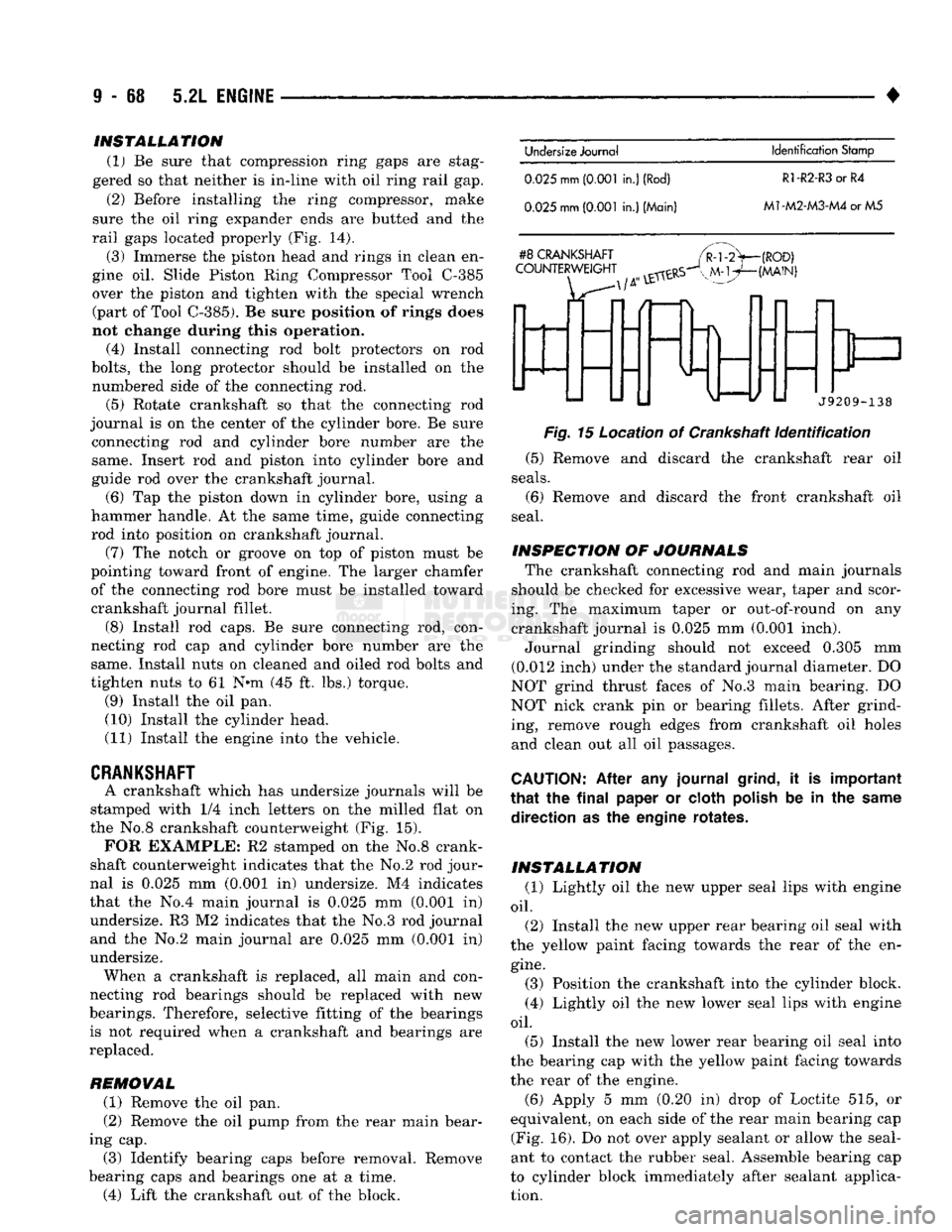
A crankshaft which has undersize journals will be
stamped with 1/4 inch letters on the milled flat on
the No.8 crankshaft counterweight (Fig. 15).
FOR
EXAMPLE: R2 stamped on the No.8 crank
shaft counterweight indicates that the No.2 rod jour
nal is 0.025 mm (0.001 in) undersize. M4 indicates
that the No.4 main journal is 0.025 mm (0.001 in) undersize. R3 M2 indicates that the No.3 rod journal and the No.2 main journal are 0.025 mm (0.Q01 in)
undersize. When a crankshaft is replaced, all main and con
necting rod bearings should be replaced with new
bearings. Therefore, selective fitting of the bearings is not required when a crankshaft and bearings are
replaced.
REMOVAL (1) Remove the oil pan.
(2) Remove the oil pump from the rear main bear
ing cap. (3) Identify bearing caps before removal. Remove
bearing caps and bearings one at a time. (4) Lift the crankshaft out of the block.
Undersize
Journal
Identification
Stamp
0.025
mm
(0.001
in.)
(Rod)
R1-R2-R3
or R4
0.025
mm
(0.001
in.) (Main)
M1-M2-M3-M4
or M5
#8
CRANKSHAFT
COUNTERWEIGHT
(ROD)
(MAIN)
f
J9209-138
Fig.
15 Location of Crankshaft
Identification
(5) Remove and discard the crankshaft rear oil
seals.
(6) Remove and discard the front crankshaft oil
seal.
INSPECTION OF JOURNALS The crankshaft connecting rod and main journals
should be checked for excessive wear, taper and scor
ing. The maximum taper or out-of-round on any crankshaft journal is 0.025 mm (0.001 inch). Journal grinding should not exceed 0.305 mm
(0.012 inch) under the standard journal diameter. DO
NOT grind thrust faces of No.3 main bearing. DO
NOT nick crank pin or bearing fillets. After grind ing, remove rough edges from crankshaft oil holes
and clean out all oil passages.
CAUTION:
After any journal
grind,
it is important
that
the
final
paper or cloth
polish
be in the
same
direction as the engine rotates.
INSTALLATION (1) Lightly oil the new upper seal lips with engine
oil.
(2) Install the new upper rear bearing oil seal with
the yellow paint facing towards the rear of the en
gine.
(3) Position the crankshaft into the cylinder block.
(4) Lightly oil the new lower seal lips with engine
oil.
(5) Install the new lower rear bearing oil seal into
the bearing cap with the yellow paint facing towards
the rear of the engine.
(6)
Apply 5 mm (0.20 in) drop of Loctite 515, or
equivalent, on each side of the rear main bearing cap (Fig. 16). Do not over apply sealant or allow the seal
ant to contact the rubber seal. Assemble bearing cap
to cylinder block immediately after sealant applica tion.
Page 682 of 1502
5.9L
ENGINE SERVICE PROCEDURES
INDEX
page
Camshaft
91
Crankshaft
98
Crankshaft Main Bearings
99
Crankshaft Rear
Oil
Seals
100
Cylinder
Block
101
Cylinder
Head Cover
81
Cylinder
Heads
82
Distributor
92
Engine Assembly
80
Engine
Front
Mounts
77
Engine Rear Mount
78
Front
Crankshaft
Oil
Seal Replacement
91
page
General
Information
77
Hydraulic
Tappets
87
Oil
Pan 93
Oil Pump
. 94
Piston
/
Connecting
Rod
Assembly
96
Rocker Arms
81
Specifications—5.9L
Engine
103
Timing
Chain Cover
89
Valve Stem Shield
/
Spring Replacement
86
Valve
Timing
. 88
Valves
/
Valve Springs
84
Vibration
Damper
88
GENERAL
INFORMATION
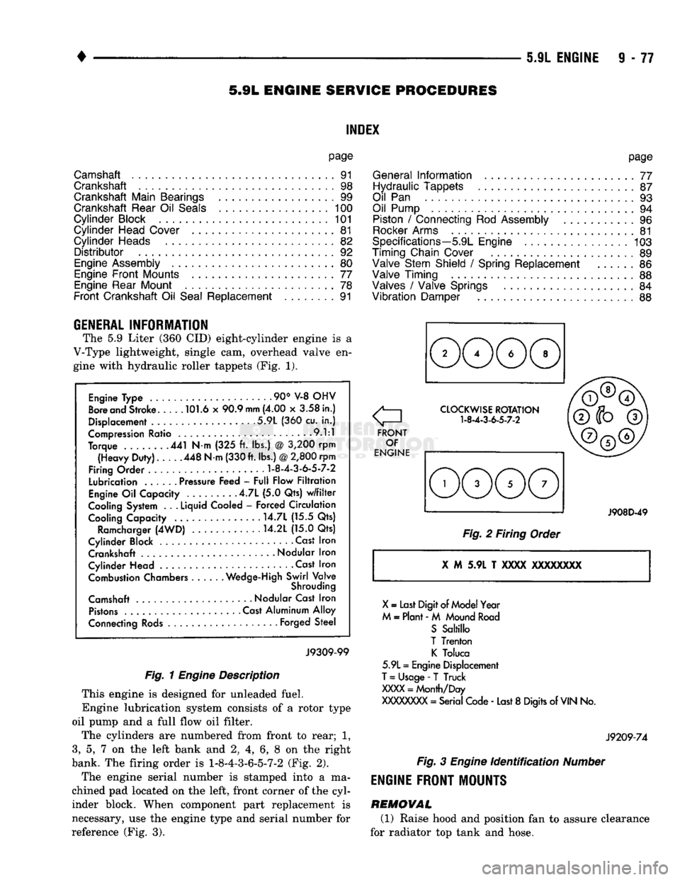
The 5.9 Liter (360 CID) eight-cylinder engine is a
V-Type lightweight, single cam, overhead valve en
gine with hydraulic roller tappets (Fig. 1).
Engine Type .90° V-8 OHV
Bore and Stroke 101.6 x 90.9
mm
(4.00 x 3.58 in.)
Displacement 5.9L (360 cu. in.)
Compression Ratio 9.1:1
Torque 441 N-m (325 ft. lbs.) @ 3,200 rpm (Heavy Duty). 448 N-m (330 ft. lbs.)
@
2,800 rpm
Firing Order
1-8-4-3-6-5-7-2
Lubrication ...... Pressure Feed - Full Flow Filtration
Engine Oil Capacity .4.7L (5.0 Qts) w/filter
Cooling System . .
.
Liquid Cooled - Forced Circulation Cooling Capacity ..... . . 14.7L (15.5 Qts)
Ramcharger (4WD) 14.2L (15.0 Qts)
Cylinder Block Cast Iron Crankshaft
-
Nodular Iron
Cylinder Head • . Cast Iron Combustion Chambers Wedge-High Swirl Valve
Shrouding
Camshaft Nodular Cast Iron Pistons Cast Aluminum Alloy
Connecting Rods Forged Steel
J9309-99
Fig. 1
Engine
Description
This engine is designed for unleaded fuel.
Engine lubrication system consists of a rotor type
oil pump and a full flow oil filter.
The cylinders are numbered from front to rear; 1,
3,
5, 7 on the left bank and 2, 4, 6, 8 on the right
bank. The firing order is
1-8-4-3-6-5-7-2
(Fig. 2).
The engine serial number is stamped into a ma
chined pad located on the left, front corner of the cyl
inder block. When component part replacement is
necessary, use the engine type and serial number for
reference (Fig. 3).
o
FRONT OF
ENGINE CLOCKWISE ROTATION
1-8-4-3-6-5-7-2
J908D-49
Fig. 2 Firing Order
X
M 5.9L T
XXXX
XXXXXXXX
X
= Last Digit of Model Year
M = Plant - M Mound Road S Saltillo
T Trenton K Toluca
5.9L = Engine Displacement
T
= Usage -
T
Truck
XXXX
= Month/Day
XXXXXXXX
= Serial Code - Last 8 Digits of
VIN
No.
J9209-74
Fig.
3
Engine
identification
Number
ENGINE
FRONT MOUNTS
REMOVAL (1) Raise hood and position fan to assure clearance
for radiator top tank and hose.
Page 712 of 1502
•
5.9L
(DIESEL)
ENGINE
9 -
107
5.9L
(DIESEL)
ENGINE
SERVICE
PROCEDURES
INDEX
page
Camshaft
127
Crankshaft
138
Cylinder
Block
129
Cylinder
Head
113
Engine
Assembly
. 109
Engine
Front
Mounts
(Insulators
/
Brackets)
... 107
Engine
Rear Support
108
Gear
Housing
/
Cover
122
General
Information
107
Oil Cooler Element
/
Gasket
. 149
Oil
Filter
148
page
Oil
Filter
Bypass
Valve
. 148
Oil Pan
/
Suction Tube
146
Oil Pressure Regulator Valve
/
Spring
148
Oil Pump
146
Piston
/
Connecting
Rod
Assembly
134
Rocker
Levers
/
Push
Rods
112
Specifications—5.9L Diesel Engines
151
Tappet
125
Timing
Pin
123
Valve Clearance
Adjustment
...............
121
Valves
and
Valve Springs
116
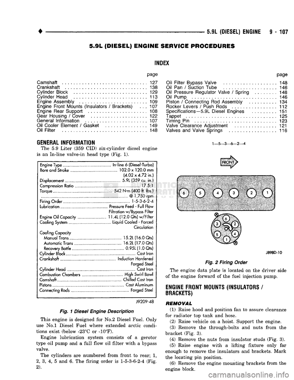
GENERAL INFORMATION The
5.9
Liter
(359 CID)
six-cylinder diesel engine
is
an
In-line valve-in head type
(Fig. 1).
Fig.
1
Diesel
Engine
Description
This engine
is
designed
for No.2
Diesel Fuel. Only
use
No.l
Diesel Fuel where extended arctic condi
tions exist (below -23°C
or -10°F).
Engine lubrication system consists
of a
gerotor
type
oil
pump
and a
full flow
oil
filter with
a
bypass valve.
The cylinders
are
numbered from front
to
rear;
1,
2,
3, 4, 5 and 6. The
firing order
is
1-5-3-6-2-4
(Fig.
2).
J898D-10
Fig.
2
Firing Order
The engine data plate
is
located
on the
driver side
of
the
engine forward
of the
fuel injection pump.
ENGINE FRONT MOUNTS (INSULATORS
/
BRACKETS)
REMOVAL (1) Raise hood
and
position
fan to
assure clearance
for radiator
top
tank
and
hose.
(2) Raise vehicle
on a
hoist. Support
the
engine.
(3) Remove
the
through-bolts
and
nuts from
the
bracket
(Fig. 3).
(4) Remove
the
nuts from insulator studs
(Fig. 3).
(5) Raise engine with
a
lifting fixture only
far
enough
to
remove
the
insulators
and
brackets. Mark
the locating
pin
position.
(6) Remove
the
engine mounting brackets from
the
engine block.
Engine Type
In-line
6
(Diesel-Turbo)
Bore and Stroke 102.0 x 120.0 mm
(4.02x4.72 in.)
Displacement 5.9L (359 cu.
in.)
Compression Ratio 17.5:1
Torque 542 N-m (400 ft. lbs.)
@
1,750 rpm
Firing Order
1-5-3-6-2-4
Lubrication Pressure Feed - Full Flow
Filtration w/Bypass Filter
Engine Oil Capacity
11.4L
(12.0 Qts) w/Filter
Cooling System Liquid Cooled
-
Forced
Circulation
Cooling Capacity
Manual Trans 15.2L (16.0 Qts)
Automatic Trans 16.2L (17.0 Qts)
Recovery Bottle 0.95L(1.0Qts)
Cylinder Block.... Cast Iron
Crankshaft Induction Hardened
Forged Steel
Cylinder Head Cast Iron
Combustion Chambers High Swirl Bowl
Camshaft.... Chilled Cast Iron
Pistons Cast Aluminum
Connecting Rods Forged Steel
J9209-48
Page 878 of 1502
•
FUEL SYSTEM
14 - 59
fill
DHADn
HIAf5MflCTipQ
/f|Rn
The powertrain control module (PCM) has been
programmed to monitor many different circuits of the
fuel injection system. If a problem is sensed in a monitored circuit often enough to indicate an actual
problem, a diagnostic trouble code (DTC) is stored.
The DTC will be stored in the PCM memory for eventual display to the service technician. If the
problem is repaired or ceases to exist, the PCM can cels the DTC after 51 engine starts.
Certain criteria must be met for a diagnostic trou
ble code (DTC) to be entered into PCM memory. The criteria may be a specific range of engine rpm, en
gine temperature and/or input voltage to the PCM.
It is possible that a DTC for a monitored circuit
may not be entered into memory even though a mal
function has occurred. This may happen because one
of the DTC criteria for the circuit has not been met. Example: assume that one of the criteria for the
MAP sensor circuit is that the engine must be oper ating between 750 and 2000 rpm to be monitored for
a DTC. If the MAP sensor output circuit shorts to
ground when the engine rpm is above 2400 rpm, a 0
volt input will be seen by the PCM. A DTC will not
be entered into memory because the condition does not occur within the specified rpm range.
A DTC indicates that the powertrain control mod
ule (PCM) has recognized an abnormal signal in a
circuit or the system. A DTC may indicate the result
of a failure, but never identify the failed component
directly.
There are several operating conditions that the
PCM does not monitor and set a DTC for. Refer to
the following Monitored Circuits and Non-Monitored Circuits in this section.
MONITORED
CIRCUITS
The powertrain control module (PCM) can detect
certain problems in the fuel injection system.
Open or Shorted Circuit - The PCM can deter
mine if sensor output (which is the input to PCM) is
within proper range. It also determines if the circuit is open or shorted.
Output Device Current Flow - The PCM senses
whether the output devices are hooked up.
If there is a problem with the circuit, the PCM
senses whether the circuit is open, shorted to ground
(-), or shorted to
(
+
)
voltage.
Oxygen Sensor - The PCM can determine if the
oxygen sensor is switching between rich and lean.
This is, once the system has entered Closed Loop. Re fer to Open Loop/Closed Loop Modes Of Operation in
the Component Description/System Operation section
for an explanation of Closed (or Open) Loop opera tion.
NON-MONITORED CIRCUITS
The PCM does not monitor the following circuits,
systems or conditions that could have malfunctions
that result in driveability problems. A diagnostic trouble code (DTC) may not be displayed for these
conditions.
Fuel Pressure: Fuel pressure is controlled by the
vacuum assisted fuel pressure regulator. The PCM
cannot detect a clogged fuel pump inlet filter, clogged
in-line fuel filter, or a pinched fuel supply or return
line.
However, these could result in a rich or lean
condition causing an oxygen sensor DTC to be stored in the PCM.
Secondary Ignition Circuit: The PCM cannot de
tect an inoperative ignition coil, fouled or worn spark
plugs,
ignition cross firing, or open circuited spark
plug cables.
Engine Timing: The PCM cannot detect an incor
rectly indexed timing chain, camshaft sprocket or crankshaft sprocket. The PCM also cannot detect an
incorrectly indexed distributor. However, these could
result in a rich or lean condition causing an oxygen
sensor DTC to be stored in the PCM.
Cylinder Compression: The PCM cannot detect
uneven, low, or high engine cylinder compression.
Exhaust System: The PCM cannot detect
a
plugged, restricted or leaking exhaust system.
Fuel Injector Malfunctions: The PCM cannot de
termine if the fuel injector is clogged, or the wrong injector is installed. However, these could result in a
rich or lean condition causing an oxygen sensor DTC
to be stored in the PCM.
Excessive Oil Consumption: Although the PCM
monitors exhaust stream oxygen content through ox
ygen sensor (closed loop), it cannot determine exces sive oil consumption.
Throttle Body Air Flow: The PCM cannot detect
a clogged or restricted air cleaner inlet or air filter
element.
Evaporative System: The PCM will not detect a
restricted, plugged or loaded EVAP canister. Vacuum Assist: Leaks or restrictions in the vac
uum circuits of vacuum assisted engine control sys
tem devices are not monitored by the PCM. However, a vacuum leak at the MAP sensor will be monitored
and a diagnostic trouble code (DTC) will be gener
ated by the PCM.
Powertrain Control Module (PCM) System
Ground: The PCM cannot determine a poor system
ground. However, a DTC may be generated as a re
sult of this condition.
Powertrain Control Module (PCM) Connector
Engagement: The PCM cannot determine spread or
damaged connector pins. However, a DTC may be generated as a result of this condition.
Page 921 of 1502
14
- 102
FUEL
SYSTEM
—
•
SYMPTOM
CAUSI
ACTION
lupin*
mimes under Im4 Incorrect
injection
pump
timing
Adjust
injection
pump
timing
Restricted
or
damaged
injector
nozzle
Replace
or
repair
as
necessary
Restricted
or
blocked
fuel
injection
lines Install
fittings
proper positions
Fuel
Injection
pump malfunction
or
not adjustable
Replace
fuel
injection
pump
lew power Improper
fuel
Drain
fuel
tank, flush
system,
fill
with
proper
fuel
Empty
fuel
tank or
fuel
tank vent blocked
Fill
tank, bleed
system,
check tank vent
Control lever not going
to full throttle
position Adjust
throttle
linkage
Clogged
fuel
filter
Replace
fuel
filter
Intercooler
internally
blocked
or
leaking
Check
pressure
drop
across
intercooler.
If
pressure
drop is more than
4
in.
Hg,
clean
or replace
as
necessary.
Restricted
or
blocked
fuel
supply lines
Remove
restrictions
or
replace lines
Injection
pump overflow
fitting
switched
with
inlet
fitting
Install
fittings
in
proper positions
Leaking
injection
lines, damaged lines
or
loose
connections
Replace
damaged
lines
or
tighten
connections
as
necessary.
Bleed
fuel
system
Incorrect
injection
pump
to
engine
timing
Adjust
injection
pump
timing
Restricted or
damaged
injector
nozzle
Repair
or replace as
necessary
Clogged
or
restricted
air filter
Remove
restrictions
or
replace
filter if
necessary
Air
fuel
control
tube broken
or
leaking
Repair
or replace
as
necessary
Low
manifold pressure
Check
and repair turbocharger operation.
Check
intercooler and
air
pipes
for
blockage
Injection
sequence
does
not correspond
with
firing
order Install
fuel
injection
lines in correct
order
Low
or
uneven
engine
compression
Repair
as
necessary
Restricted or blocked
fuel
injection
lines
Remove
restrictions
or
replace lines
Incorrect
injection
pump
to
engine
timing
Check
injection
pump
to
engine
timing
Fuel
injection
pump malfunction
or
not adjustable
Replace
fuel
injection
pump J9114-253
DIESEL
FUEL
INJECTION
SYSTEM
DIAGNOSIS-CONTINUED
Page 922 of 1502
FUEL
SYSTEM
14-103
DIESEL FUEL
INJECTION
SYSTEM DIAGNOSIS-CONTINUED
SYMPTOM
CAUSE
ACTION
Excessive
fuel
consumption improper diesel
fuel
Use
correct
fuel
for conditions. Refer
to
owner's manual
Incorrect injection pump timing
Adjust
injection pump timing
Restricted or damaged
injector
nozzle Repair or replace as necessary
Clogged
or
restricted air
filter
Remove
restrictions or replace air
filter
if
necessary
Injection sequence does not correspond
with
firing order install
fuel
injection lines in correct order
Intercooler internally blocked
or
leaking
Check
pressure drop
across
intercooler.
If
pressure drop
is
more than
4
in. Hg,
clean or replace as necessary
Low
idle misadjusted
Adjust
idle stop screw
Malfunctioning
KSB
valve
Replace
injection pump
Incorrect injection pump to engine timing
Adjust
injection pump to engine timing
Fuel injection pump malfunction or
not adjustable
Replace
fuel
injection pump
Unabie to shut engine off Voltage to
fuel
solenoid
interrupted
or
fuel
solenoid
inoperative Correct voltage supply problem or
replace
solenoid
Either poor
performance,
black moke
or
low power Improper
fuel
Drain
fuel
tank, flush
system,
fill
with
proper
fuel
for conditions. Refer to owner's
manual
Air
in
fuel
system
Bleed
fuel
system
Intercooler internally blocked
or
leaking
Check
pressure drop
across
intercooler.
If
pressure drop is more than
4
in. Hg,
clean
or
replace
as
necessary
Restricted or blocked
fuel
injection lines
Remove
restrictions or replace lines
Incorrect injection pump timing
Adjust
injection pump timing
Restricted or damaged
injector
nozzle
Repair
or replace as necessary
Clogged
or restricted air
filter
Remove
restrictions or replace
filter
if
necessary
Air
fuel
control tube leaking or broken Repair or replace as necessary
Low
manifold pressure
Check
and repair turbocharger operation
Injection sequence does not correspond
with
firing order Install
fuel
injection lines in correct order
—
Low
or uneven engine compression
Repair as necessary
J9114-255