•
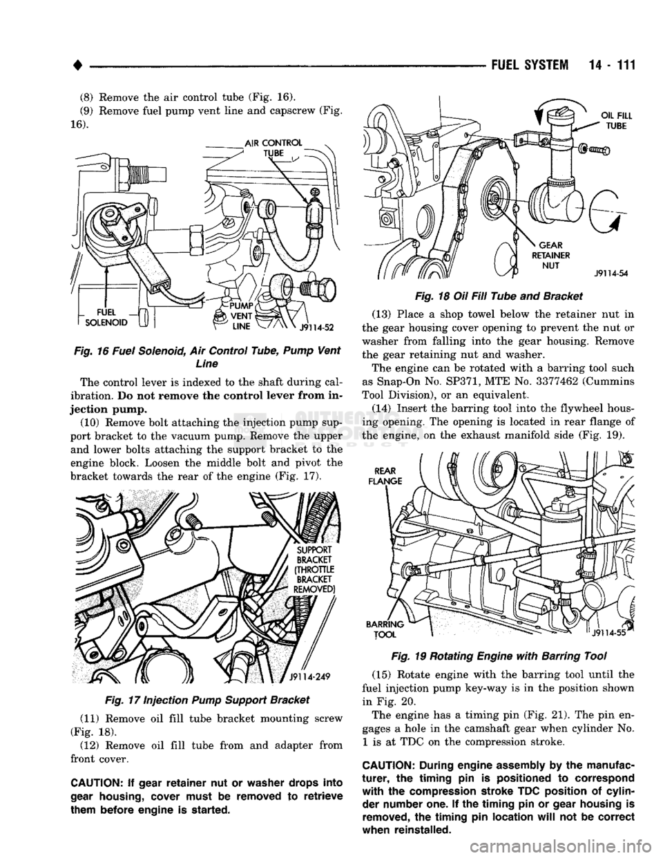
(8) Remove the air control tube (Fig. 16).
(9) Remove fuel pump vent line and capscrew (Fig.
16).
Fig.
16 Fuel Solenoid, Air Control Tube,
Pump
Vent Line
The control lever is indexed to the shaft during cal
ibration. Do not remove the control lever from in
jection pump. (10) Remove bolt attaching the injection pump sup
port bracket to the vacuum pump. Remove the upper and lower bolts attaching the support bracket to the
engine block. Loosen the middle bolt and pivot the
bracket towards the rear of the engine (Fig. 17).
Fig.
17 Injection
Pump
Support
Bracket
(11) Remove oil fill tube bracket mounting screw
(Fig. 18). (12) Remove oil fill tube from and adapter from
front cover.
CAUTION:
If
gear
retainer
nut or
washer drops into
gear
housing,
cover must
be
removed
to
retrieve
them before engine
is
started. FUEL
SYSTEM
14-111
Fig.
18 Oil Fill Tube and Bracket (13) Place a shop towel below the retainer nut in
the gear housing cover opening to prevent the nut or
washer from falling into the gear housing. Remove
the gear retaining nut and washer.
The engine can be rotated with a barring tool such
as Snap-On No.
SP371,
MTE No. 3377462 (Cummins
Tool Division), or an equivalent.
(14) Insert the barring tool into the flywheel hous
ing opening. The opening is located in rear flange of
the engine, on the exhaust manifold side (Fig. 19).
Fig.
19 Rotating
Engine
with
Barring Tool
(15) Rotate engine with the barring tool until the
fuel injection pump key-way is in the position shown in Fig. 20.
The engine has a timing pin (Fig. 21). The pin en
gages a hole in the camshaft gear when cylinder No. 1 is at TDC on the compression stroke.
CAUTION:
During
engine
assembly
by the
manufac
turer,
the
timing
pin is
positioned
to
correspond
with
the
compression stroke TDC position
of
cylin der number one.
If the
timing
pin or
gear housing
is
removed,
the
timing
pin
location
will
not be
correct
when reinstalled.
•
PROPELLER SHAFTS
16 - 7 ADJUSTMENT AT AXLE WITH LEAF SPRINGS
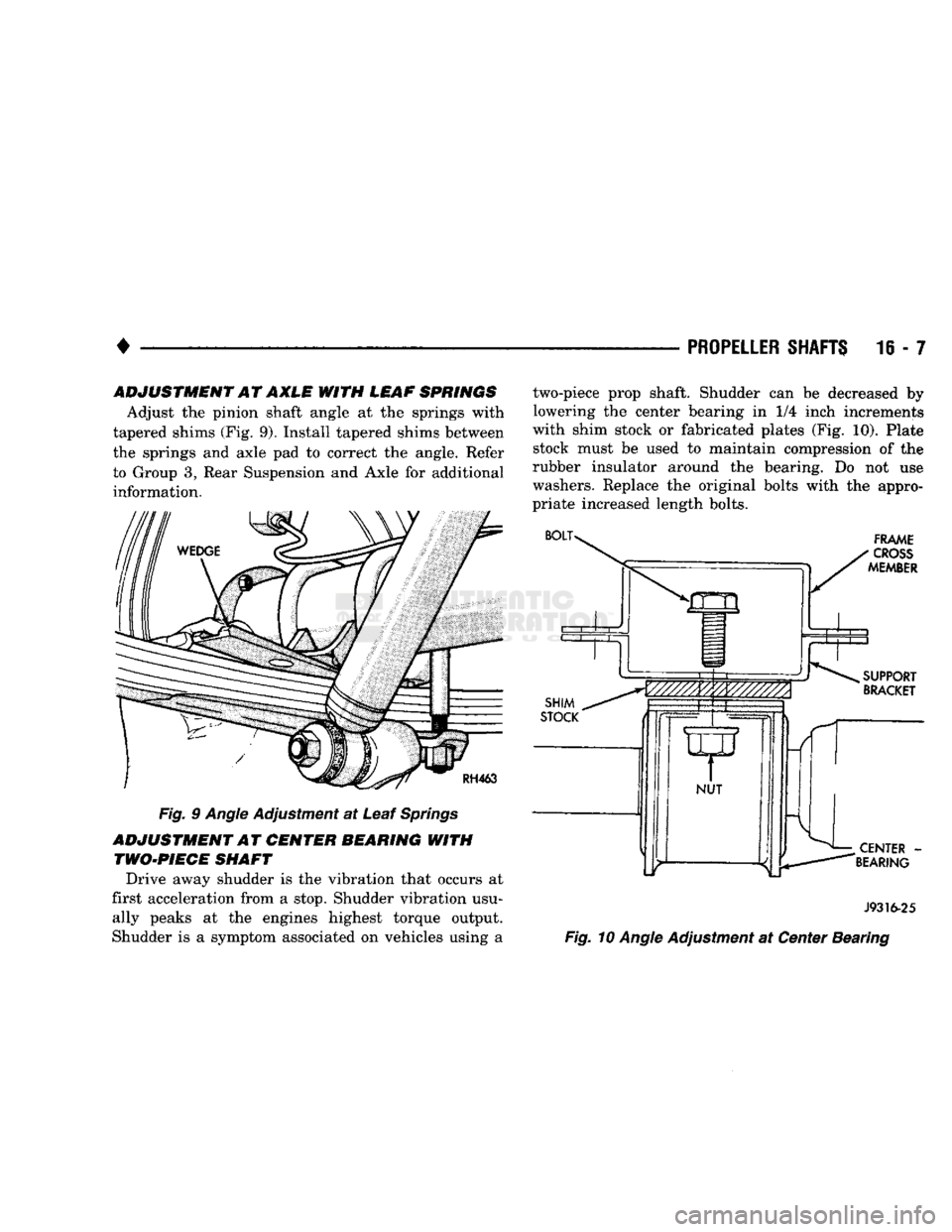
Adjust the pinion shaft angle at the springs with
tapered shims (Fig. 9). Install tapered shims between
the springs and axle pad to correct the angle. Refer to Group 3, Rear Suspension and Axle for additional information.
Fig. 9 Angle Adjustment at Leaf Springs
ADJUSTMENT AT CENTER BEARING WITH TWO-PIECE SHAFT
Drive away shudder is the vibration that occurs at
first acceleration from a stop. Shudder vibration usu ally peaks at the engines highest torque output.
Shudder is a symptom associated on vehicles using a two-piece prop shaft. Shudder can be decreased by
lowering the center bearing in 1/4 inch increments
with shim stock or fabricated plates (Fig. 10). Plate stock must be used to maintain compression of the
rubber insulator around the bearing. Do not use
washers. Replace the original bolts with the appro
priate increased length bolts.
J9316-25
Fig. 10 Angle Adjustment at Center Bearing