1993 DODGE TRUCK clock
[x] Cancel search: clockPage 34 of 1502

•
LUBRICATION
AND
MAINTENANCE
0 - 15
DIESEL
ENGINES
The Diesel engine oil level indicator is located at
the left center of the engine, above the
fuel
injection
pump (Fig. 3).
Fig.
3
Diesel
Engine
Oil
Dipstick
ACCEPTABLE
OIL
LEVEL
To maintain proper lubrication of an engine, the
engine oil must be maintained at an acceptable level.
For gasoline engines, the acceptable levels are indi cated between the ADD and
FULL
marks on oil
dip
stick. For Diesel engines, the acceptable levels are
indicated between the L (low) and H
(high) marks
on
oil dipstick. The oil level should be checked periodically. The
vehicle should be on a level surface. Wait for
five
minutes after stopping the engine. For gasoline en
gines,
add oil only when the level indicated on the
dipstick is at or below the ADD mark. For Diesel en
gines,
add oil only when the level indicated on the
dipstick is between the L and H marks.
Never oper
ate a Diesel
engine when
the oil
level
is below
the L mark. The distance between the L and H
marks represents 1.9L (2 Qts) engine oil.
CAUTION:
Do not
overfill
an
engine crankcase
with
oil. This
will
cause
oil
aeration
and
result
in a de
crease
in the
engine
oil
pressure.
ENGINE
OIL
CHANGE AND FILTER REPLACEMENT
WARNING: PROTECTIVE CLOTHING
AND
GLOVES SHOULD
BE
WORN. EXPOSED SKIN SHOULD
BE
WASHED
WITH
SOAP
AND
WATER
TO
REMOVE
USED
ENGINE
OIL.
DO NOT
USE
GASOLINE, THIN
NER,
OR
SOLVENTS
TO
REMOVE ENGINE
OIL
FROM
SKIN.
DO NOT
POLLUTE. DISPOSE
OF
USED
ENGINE
OIL
PROPERLY.
ENGINE
OIL
FILTER
All engines are equipped with a throw-away type
oil filter. The same type of filter is recommended
when the filter is changed.
OIL CHANGE
AND
FILTER
REPLACEMENT
Bring engine up to normal operating temperature.
A more complete drainage of oil will result.
(1) Remove the drain hole plug and drain the en
gine oil from the crankcase.
(2) Install the drain hole plug with a replacement
gasket. For gasoline engines, the oil filter should be
replaced during every second engine oil change.
For Diesel engines, the oil filter should be re
placed during every engine oil change.
(3) Rotate the oil filter counterclockwise to remove
it.
(4) Clean the engine cylinder block oil filter boss. (5) Apply a light coat of new engine oil to the rub
ber seal on the oil filter.
(6) Install and hand tighten the oil filter 1/2 to 3/4
of a turn clockwise. (7) Add new engine oil at the fill hole location on
top of the engine cylinder head cover. Wipe off any spilled oil.
(8) Observe the oil level on the dipstick.
CAUTION:
Do not
overfill
the
engine crankcase
with
oil.
(9)
Start the engine. Observe the oil pressure
gauge or warning lamp (as applicable). If the oil
pressure does not increase, stop the engine immedi ately. Check oil level.
COOLING SYSTEM
WARNING:
USE
EXTREME CAUTION WHEN
THE
ENGINE
IS
OPERATING.
DO NOT PUT
YOUR
HANDS NEAR
THE
DRIVE BELT(S), PULLEYS
OR
FAN BLADE.
DO NOT
STAND
IN A
DIRECT LINE
WITH
THE FAN
BLADE.
INSPECTION SCHEDULE
Determine the coolant level. Inspect the cooling
system hoses/clamps after each service interval has
elapsed.
COOLANT LEVEL
It is recommended that the engine coolant level be
inspected at least once a month during periods of hot
weather.
With the engine at normal operating temperature,
check the coolant level in the coolant reserve tank.
The coolant level must be at least above the ADD mark. Add coolant to the coolant reserve tank only.
Page 35 of 1502
0-18
LUBRICATION
AND
MAINTENANCE
•
COOLANT FREEZE PROTECTION
Cooling systems contain a 50/50 mixture of anti
freeze (ethylene glycol) and distilled water. This is
the recommended coolant mixture.
It is recommended that the degree of coolant pro
tection be tested every 12 months. If the coolant is
contaminated or rusty, the cooling system should be
drained, flushed. Refill with a 50/50 mixture of fresh
coolant. Refer to Group 7—Cooling Systems for addi
tional information.
SYSTEM
INSPECTION
WARNING:
IF THE
ENGINE
HAS
BEEN RECENTLY
OPERATED,
DO NOT
REMOVE
THE
RADIATOR
CAP.
THIS WILL AVOID
YOU
BEING SCALDED
WITH
HOT, PRESSURIZED COOLANT.
(1) Test the radiator cap for proper sealing and op
eration. Use caution when removing the radiator cap
to avoid contact with hot coolant. Place a heavy rag
or towel over the cap and turn to the first stop. Do
not press down. Pause to allow the pressure to re
lease through the overflow tube. Then press down
and turn counterclockwise to remove the cap.
(2) Inspect the coolant overflow tubing and the
connections at the coolant reserve tank and at the
radiator.
(3) Inspect the entire cooling system for leaks. A
black-light detector can be used as an aid in detect ing the source of coolant leaks.
(4) Inspect the radiator and air conditioner con
denser fins for debris, etc. (5) If necessary, refer to Group 7—Cooling Systems
for additional information and service procedures.
RADIATOR CAP
The radiator cap must be completely tightened to
provide proper pressure. Inspect and test radiator cap
when cooling system service is performed.
MAIN,
FLUSH
AND
FILL
WARNING: ANTI-FREEZE (ETHYLENE GLYCOL)
IS
POISONOUS.
KEEP
OUT OF THE
REACH
OF
CHIL
DREN.
Drain, flush, and fill the cooling system at the in
terval specified in maintenance schedule. For proper service instructions see Group 7, Cooling System.
HOSES AND
FITTINGS
It is recommended that rubber hoses be periodi
cally inspected. Inspect all hose fittings for looseness and corrosion.
ENGINE
AIR
CLEANER
FILTER
ELEMENT
MAINTENANCE
SCHEDULE
With normal driving conditions, the engine air
cleaner filter element should be replaced:
• Light-Duty Cycle-after each 48 000 km (30,000
miles) interval has elapsed
• Heavy-Duty Cycle-after
each
38 000 km (24,000
miles) interval has elapsed
When the vehicle is operated in dusty areas, the
filter element should be replaced more often.
For Diesel engines, the air filter canister should be
cleaned at the same time the filter is replaced.
SERVICE/REPLACEMENT
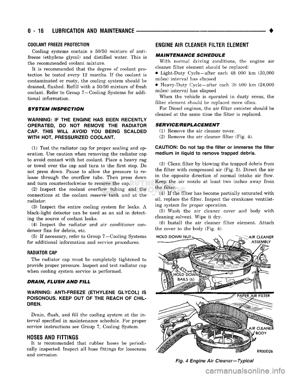
(1) Remove the air cleaner cover.
(2) Remove the air cleaner filter (Fig. 4).
CAUTION:
Do not tap the filter or immerse the filter medium in liquid to remove trapped debris.
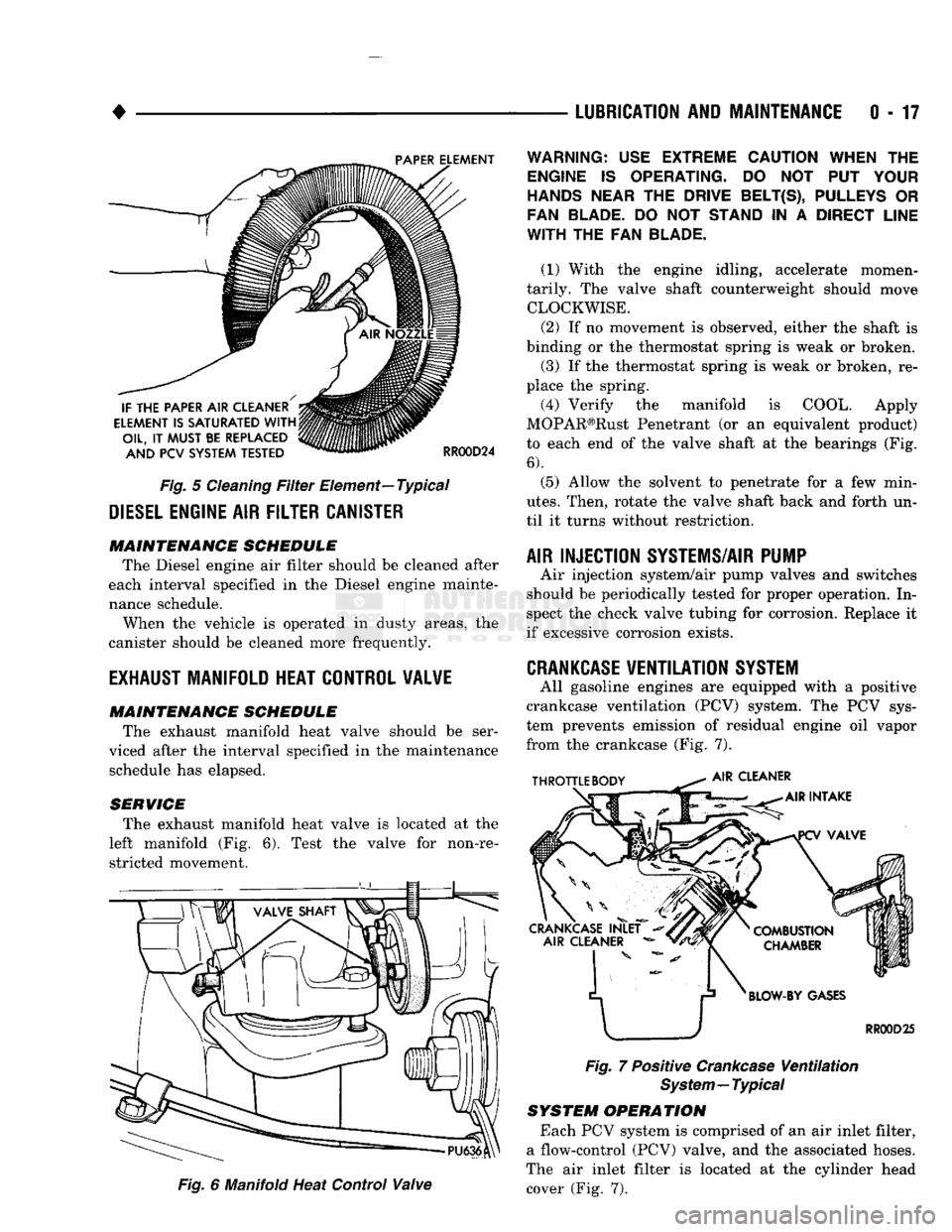
(3) Clean filter by blowing the trapped debris from
the filter with compressed air (Fig. 5). Direct the air in the opposite direction of normal intake air flow.
Keep the air nozzle at least two inches away from
the filter.
(4) If the filter has become partially saturated with
oil,
replace the filter. Inspect the crankcase ventilat
ing system for proper operation.
(5) Wash the air cleaner cover and body with
cleaning solvent. Wipe it dry.
(6) Install the air cleaner filter element. Attach
the cover to the body (Fig. 4).
Fig,
4
Engine
Air Oeaner—
Typical
Page 36 of 1502
•
Fig.
5
Cleaning
Filter
Element—Typical
DIESEL
ENGINE
AIR
FILTER CANISTER MAINTENANCE SCHEDULE
The Diesel engine air filter should be cleaned after
each interval specified in the Diesel engine mainte
nance schedule.
When the vehicle is operated in dusty areas, the
canister should be cleaned more frequently.
EXHAUST
MANIFOLD HEAT CONTROL VALVE
MAINTENANCE SCHEDULE
The exhaust manifold heat valve should be ser
viced after the interval specified in the maintenance schedule has elapsed.
SERVICE The exhaust manifold heat valve is located at the
left manifold (Fig. 6). Test the valve for non-re stricted movement.
Fig.
6 Manifold Heat Control
Valve
LUBRICATION
AND
MAINTENANCE
0 - 17
Fig.
7 Positive
Crankcase
Ventilation
System—Typical
SYSTEM OPERATION
Each PCV system is comprised of an air inlet filter,
a flow-control (PCV) valve, and the associated hoses.
The air inlet filter is located at the cylinder head cover (Fig. 7).
WARNING:
USE
EXTREME CAUTION WHEN
THE
ENGINE
IS
OPERATING.
DO NOT PUT
YOUR
HANDS NEAR
THE
DRIVE BELT(S), PULLEYS
OR
FAN BLADE.
DO NOT
STAND
IN A
DIRECT LINE
WITH
THE FAN
BLADE.
(1) With the engine idling, accelerate momen
tarily. The valve shaft counterweight should move CLOCKWISE.
(2) If no movement is observed, either the shaft is
binding or the thermostat spring is weak or broken. (3) If the thermostat spring is weak or broken, re
place the spring.
(4) Verify the manifold is COOL. Apply
MOPAR®Rust Penetrant (or an equivalent product)
to each end of the valve shaft at the bearings (Fig.
6).
(5) Allow the solvent to penetrate for a few min
utes.
Then, rotate the valve shaft back and forth un
til it turns without restriction.
AIR INJECTION SYSTEMS/AIR PUMP
Air injection system/air pump valves and switches
should be periodically tested for proper operation. In
spect the check valve tubing for corrosion. Replace it
if excessive corrosion exists.
CRANKCASE
VENTILATION
SYSTEM
All gasoline engines are equipped with a positive
crankcase ventilation (PCV) system. The PCV sys
tem prevents emission of residual engine oil vapor
from the crankcase (Fig. 7).
Page 56 of 1502
FRONT SUSPENSION
AND
AXLE
2 - 3
FRONT
WHEEL
ALIGNMENT
GENERAL
INFORMATION
Front wheel alignment involves
the
correct posi
tioning
of the
tire contact patch
in
relation
to the
pavement.
The
positioning
is
accomplished through
the suspension
and
steering linkage adjustments.
An
alignment
is
essential
for
efficient steering
and
direc
tional stability.
The
most important factors
of
front
end alignment
are
camber, caster
and toe
position. Routine inspection
of
the front
suspension
and
steering components
is a
good
preventative
maintenance practice.
Inspection
also
helps
to
ensure
safe operation
of the
vehicle.
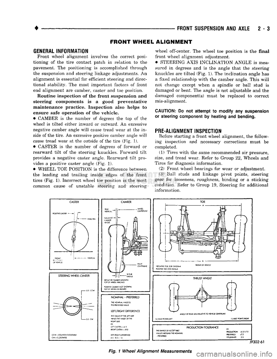
• CAMBER
is the
number
of
degrees
the top of the
wheel
is
tilted either inward
or
outward.
An
excessive
negative camber angle will cause tread wear
at the in
side
of
the tire.
An
excessive positive camber angle will
cause tread wear
at the
outside
of
the tire (Fig.
1),
• CASTER
is the
number
of
degrees
of
forward
or
rearward tilt
of the
steering knuckles. Forward tilt
provides
a
negative caster angle. Rearward tilt pro vides
a
positive caster angle
(Fig. 1).
• WHEEL
TOE
POSITION
is the
difference between
the leading
and
trailing inside edges
of the
front
tires (Fig.
1).
Incorrect wheel
toe
position
is the
most common cause
of
unstable steering
and
steering wheel off-center.
The
wheel
toe
position
is the
final
front wheel alignment adjustment. • STEERING AXIS INCLINATION ANGLE
is
mea
sured
in
degrees
and is the
angle that
the
steering
knuckles
are
tilted (Fig. 1).
The
inclination angle
has
a fixed relationship with
the
camber angle. This will
not change except when
a
spindle
or
ball stud
is
damaged
or
bent.
The
angle
is not
adjustable
and the
damaged component(s) must
be
replaced
to
correct
mis-alignment.
CAUTION:
Do not
attempt to modify
any
suspension
or steering
component
by
heating
and
bending.
PRE-ALIGNMENT INSPECTION
Before starting
a
front wheel alignment,
the
follow
ing inspection
and
necessary corrections must
be
completed.
(1)
Tires with
the
same recommended
air
pressure,
size,
and
tread wear. Refer
to
Group
22,
Wheels
and
Tires
for
diagnosis information. (2) Front wheel bearings
for
wear
or
adjustment.
(3) Ball studs
and
linkage pivot points, steering
gear
for
looseness, roughness, binding
or a
sticking
condition. Refer
to
Group
19,
Steering
for
additional information.
CASTER
POSITIVE CASTER
STEERING
WHEEL CENTER
i 0.5
CCW
0
5
CW
CCW
=
COUNTER CLOCKWISE
CW
-
CLOCKWISE
CAMBER
NEGATIVE CAMBER (SHOWN)
TOP
OF
WHEEL INBOARD
POSITIVE CAMBER
(NOT
SHOWN)
TOP
OF
WHEEL OUTBOARD
NOMINAL-PREFERRED
THE NOMINAL VALUE
IS
THE
PREFERRED
VALUE
LEFT/RIGHT
DIFFERENCE
THE VALUE
Of
THE LEFT SIDE
MINUS THE VALUE
OF
THE
RIGHT SIDE
EX.
If
FT CASTER
- +6 5
RIGHT
CASTER
»
+8.0
LEFT/RIGHT DIFFERENCE
65 8.0
=
1
5
TOE
NEGATIVE TOE (TOE
OUT)
B>A
POSITIVE TOE (TOE
IN) 6
FRONT
Of
VEHICLE
ft
THRUST
ANGLE
ANGLE
OF
REAR
AXLE RELATIVE
TO
VEHICLE CENTERUNE
(+)
AXLE POINTS LEFT
(-)
AXLE POINTS RIGHT
PRODUCTION
TOLERANCE
THE RANGE
Of
ACCEPTABLE
VALUES
AROUND THE NOMINAL
-
PREFERRED PRODUCTION
+6.5A7.5
PREFERRED:
+7.0
TOLERANCE:
0.5
J9302-61
Fig.
1
Wheel
Alignment
Measurements
Page 195 of 1502
i - 8
BRAKES
•
BRAKE
SHOE'S
Fig. 2 Adjusting Brakeshoes To Gauge standstill at each stop. Incomplete, rolling stops will
not activate the automatic adjusters.
ADJUSTMENT
WITH
TOOL
C-3784
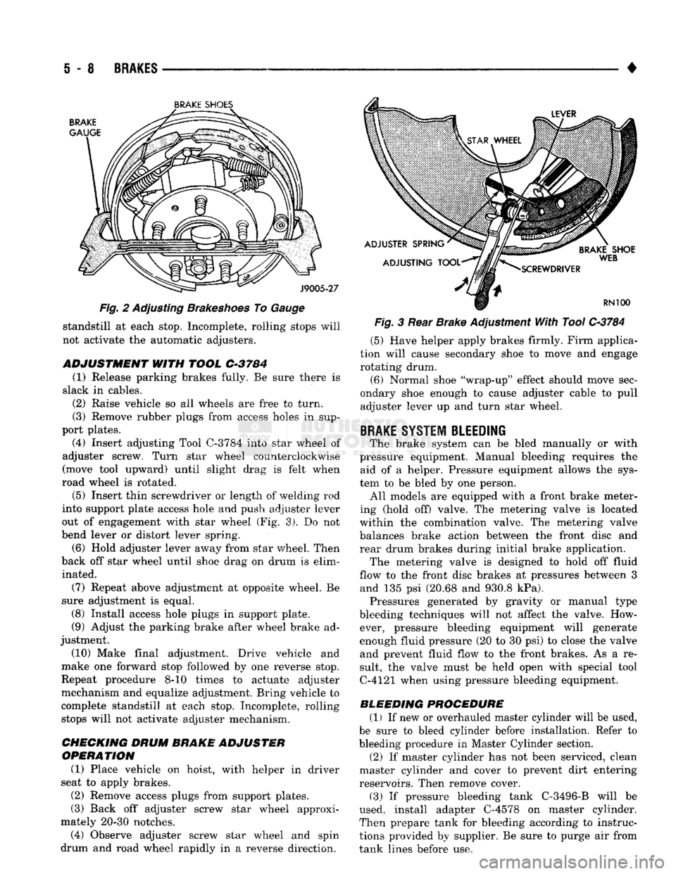
(1) Release parking brakes fully. Be sure there is
slack in cables. (2) Raise vehicle so all wheels are free to turn.
(3) Remove rubber plugs from access holes in sup
port plates. (4) Insert adjusting Tool
0-3784
into star wheel of
adjuster screw. Turn star wheel counterclockwise
(move tool upward) until slight drag is felt when
road wheel is rotated.
(5)
Insert thin screwdriver or length of welding rod
into support plate access hole and push adjuster lever
out of engagement with star wheel (Fig. 3). Do not
bend lever or distort lever spring.
(6) Hold adjuster lever away from star wheel. Then
back off star wheel until shoe drag on drum is elim inated.
(7) Repeat above adjustment at opposite wheel. Be
sure adjustment is equal. (8) Install access hole plugs in support plate.
(9) Adjust the parking brake after wheel brake ad
justment.
(10) Make final adjustment. Drive vehicle and
make one forward stop followed by one reverse stop.
Repeat procedure 8-10 times to actuate adjuster
mechanism and equalize adjustment. Bring vehicle to
complete standstill at each stop. Incomplete, rolling stops will not activate adjuster mechanism.
CHECKING DRUM
BRAKE ADJUSTER
OPERATION
(1) Place vehicle on hoist, with helper in driver
seat to apply brakes.
(2) Remove access plugs from support plates.
(3) Back off adjuster screw star wheel approxi
mately 20-30 notches. (4) Observe adjuster screw star wheel and spin
drum and road wheel rapidly in a reverse direction. Fig. 3 Rear Brake Adjustment With Tool
C-3784
(5) Have helper apply brakes firmly. Firm applica
tion will cause secondary shoe to move and engage rotating drum.
(6) Normal shoe "wrap-up" effect should move sec
ondary shoe enough to cause adjuster cable to pull adjuster lever up and turn star wheel.
BRAKE
SYSTEM BLEEDING
The brake system can be bled manually or with
pressure equipment. Manual bleeding requires the aid of a helper. Pressure equipment allows the sys
tem to be bled by one person. All models are equipped with a front brake meter
ing (hold off) valve. The metering valve is located
within the combination valve. The metering valve balances brake action between the front disc and
rear drum brakes during initial brake application. The metering valve is designed to hold off fluid
flow to the front disc brakes at pressures between 3 and 135 psi (20.68 and 930.8 kPa). Pressures generated by gravity or manual type
bleeding techniques will not affect the valve. How ever, pressure bleeding equipment will generate
enough fluid pressure (20 to 30 psi) to close the valve and prevent fluid flow to the front brakes. As a re
sult, the valve must be held open with special tool
C-4121 when using pressure bleeding equipment.
BLEEDING PROCEDURE (1) If new or overhauled master cylinder will be used,
be sure to bleed cylinder before installation. Refer to
bleeding procedure in Master Cylinder section. (2) If master cylinder has not been serviced, clean
master cylinder and cover to prevent dirt entering
reservoirs. Then remove cover.
(3) If pressure bleeding tank C-3496-B will be
used, install adapter C-4578 on master cylinder.
Then prepare tank for bleeding according to instruc
tions provided by supplier. Be sure to purge air from
tank lines before use.
Page 257 of 1502
e - 4
CLUTCH
•
7/16 - 20
THREAD
NUT
10 INCHES LONG J9006-25
CLUTCH
HOUSING
BORE
J9006-26
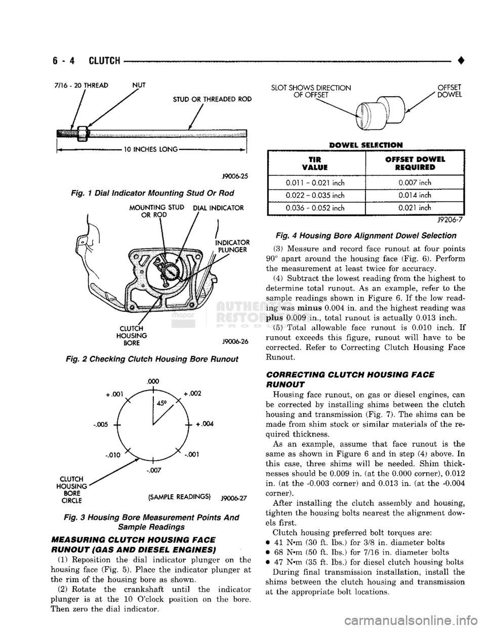
Fig.
2 Checking Clutch Housing Bore Runout
.000
CLUTCH
HOUSING
qroe {Smm READINGS) J9006-27
Fig.
3
Housing
Bore Measurement Points And Sample Readings
MEASURING
CLUTCH
HOUSING FACE
RUNOUT (GAS AND DIESEL ENGINES) (1) Reposition the dial indicator plunger on the
housing face (Fig. 5). Place the indicator plunger at
the rim of the housing bore as shown.
(2) Rotate the crankshaft until the indicator
plunger is at the 10 O'clock position on the bore.
Then zero the dial indicator.
SLOT SHOWS DIRECTION OFFSET
DOWEL
DOWEL SELECTION
TIR
VALUE OFFSET DOWEL
REQUIRED
0.011
-0.021
inch
0.007
inch
0.022
-
0.035
inch
0.014
inch
0.036
-
0.052
inch
0.021
inch
J9206-7
Fig.
4
Housing
Bore
Alignment
Dowel
Selection
(3)
Measure and record face runout at four points
90° apart around the housing face (Fig. 6). Perform
the measurement at least twice for accuracy.
(4)
Subtract the lowest reading from the highest to
determine total runout. As an example, refer to the
sample readings shown in Figure 6. If the low read
ing was minus
0.004
in. and the highest reading was
plus
0.009
in., total runout is actually
0.013
inch.
(5)
Total allowable face runout is 0.010 inch. If
runout exceeds this figure, runout will have to be
corrected. Refer to Correcting Clutch Housing Face
Runout.
CORRECTING CLUTCH HOUSING FACE
RUNOUT
Housing face runout, on gas or diesel engines, can
be corrected by installing shims between the clutch
housing and transmission (Fig. 7). The shims can be made from shim stock or similar materials of the re
quired thickness.
As an example, assume that face runout is the
same as shown in Figure 6 and in step (4) above. In
this case, three shims will be needed. Shim thick
nesses should be
0.009
in. (at the
0.000
corner),
0.012
in. (at the
-0.003
corner) and
0.013
in. (at the
-0.004
corner).
After installing the clutch assembly and housing,
tighten the housing bolts nearest the alignment dow els first.
Clutch housing preferred bolt torques are:
• 41 N-m (30 ft. lbs.) for 3/8 in. diameter bolts
• 68 Nnn (50 ft. lbs.) for 7/16 in. diameter bolts
• 47 Nth (35 ft. lbs.) for diesel clutch housing bolts During final transmission installation, install the
shims between the clutch housing and transmission at the appropriate bolt locations.
Page 268 of 1502
•
CLUTCH
6 - 15
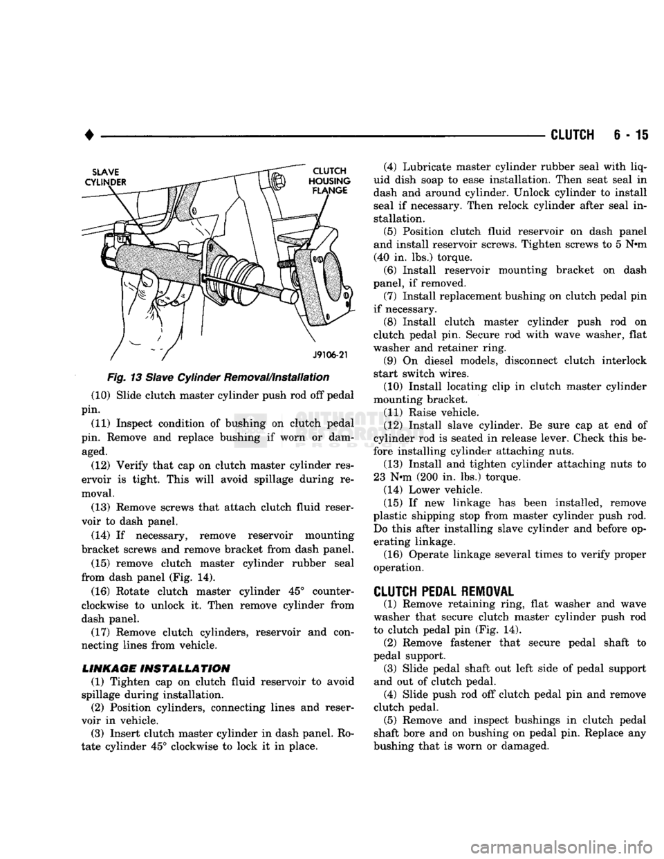
Fig.
13
Slave
Cylinder Removal/Installation (10) Slide clutch master cylinder push rod off pedal
pin.
(11) Inspect condition of bushing on clutch pedal
pin. Remove and replace bushing if worn or dam aged.
(12) Verify that cap on clutch master cylinder res
ervoir is tight. This will avoid spillage during re
moval.
(13) Remove screws that attach clutch fluid reser
voir to dash panel.
(14) If necessary, remove reservoir mounting
bracket screws and remove bracket from dash panel.
(15) remove clutch master cylinder rubber seal
from dash panel (Fig. 14).
(16) Rotate clutch master cylinder 45° counter
clockwise to unlock it. Then remove cylinder from
dash panel. (17) Remove clutch cylinders, reservoir and con
necting lines from vehicle.
LINKAGE
INSTALLATION
(1) Tighten cap on clutch fluid reservoir to avoid
spillage during installation. (2) Position cylinders, connecting lines and reser
voir in vehicle.
(3) Insert clutch master cylinder in dash panel. Ro
tate cylinder 45° clockwise to lock it in place. (4) Lubricate master cylinder rubber seal with liq
uid dish soap to ease installation. Then seat seal in
dash and around cylinder. Unlock cylinder to install
seal if necessary. Then relock cylinder after seal in stallation.
(5) Position clutch fluid reservoir on dash panel
and install reservoir screws. Tighten screws to 5 N»m (40 in. lbs.) torque.
(6) Install reservoir mounting bracket on dash
panel, if removed.
(7) Install replacement bushing on clutch pedal pin
if necessary. (8) Install clutch master cylinder push rod on
clutch pedal pin. Secure rod with wave washer, flat
washer and retainer ring.
(9) On diesel models, disconnect clutch interlock
start switch wires.
(10) Install locating clip in clutch master cylinder
mounting bracket.
(11) Raise vehicle.
(12) Install slave cylinder. Be sure cap at end of
cylinder rod is seated in release lever. Check this be
fore installing cylinder attaching nuts. (13) Install and tighten cylinder attaching nuts to
23 N*m (200 in. lbs.) torque.
(14) Lower vehicle.
(15) If new linkage has been installed, remove
plastic shipping stop from master cylinder push rod. Do this after installing slave cylinder and before operating linkage.
(16) Operate linkage several times to verify proper
operation.
CLUTCH
PEDAL REMOVAL
(1) Remove retaining ring, flat washer and wave
washer that secure clutch master cylinder push rod
to clutch pedal pin (Fig. 14). (2) Remove fastener that secure pedal shaft to
pedal support. (3) Slide pedal shaft out left side of pedal support
and out of clutch pedal. (4) Slide push rod off clutch pedal pin and remove
clutch pedal. (5) Remove and inspect bushings in clutch pedal
shaft bore and on bushing on pedal pin. Replace any
bushing that is worn or damaged.
Page 286 of 1502
•
COOLING SYSTEM
7 - 15
SERVICE
PROCEDURES
INDEX
page
Coolant
26
Coolant Reserve/Overflow System
30
Cooling System Cleaning/Reverse Flushing
28
Cooling System Fan—Diesel Engine
. 37
Cooling System
Fan—Gas
Engines
36
Cooling System
Hoses
34
Draining Cooling System
27
Pressure
Testing
Radiator
Caps
............. 32
Radiator Pressure
Cap 31
Radiators
32
Refilling
the
Cooling System
28
WATER PUMPS—EXCEPT DIESEL
A centrifugal water pump circulates coolant
through the water jackets, passages, intake manifold,
radiator core, cooling system hoses and heater core.
The pump is driven from the engine crankshaft by a drive belt. The water pump impeller is pressed onto the rear
of a shaft that rotates in a bearing pressed into the
water pump body. The body has a small hole for ven
tilation. The water pump seals are lubricated by an
tifreeze in the coolant mixture. Additional lubrication is not necessary. A quick test to determine if pump is working is to
check if heater warms properly. A defective water
pump will not be able to circulate heated coolant
through the long heater hose to the heater core. The water pump on all models can be removed
without discharging the air conditioning system (if equipped).
REMOVAL The water pump on all gas powered engines is
bolted directly to the engine timing chain case/cover.
A gasket is used as a seal between the water pump
and timing chain case/cover.
If water pump is replaced because of bearing/shaft
damage or leaking shaft seal, the mechanical cooling
fan assembly should also be inspected. Inspect for fa tigue cracks, loose blades or loose rivets that could
have resulted from excessive vibration. Replace fan if any of these conditions are found. Also check condi
tion of the thermal viscous fan drive. Refer to Vis
cous Fan Drive in this group. (1) Disconnect negative battery cable from battery.
(2) Drain cooling system. Refer to Draining Cool
ing System in this group. Do not waste reusable coolant. If solution is clean,
drain coolant into a clean container for reuse.
(3)
Disconnect throttle cable from clip at top of fan
shroud.
page
Testing
Cooling System
for
Leaks
. 29
Thermostat
22
Transmission
Oil
Cooler—Diesel
35
Transmission
Oil
Cooler—Except Diesel
35
Transmission Oil-To-Air Cooler
36
Viscous
Fan
Drive
38
Water
Pump
Bypass
Hose—All
Gas
Powered
Engines
.............................. 19
Water
Pumps—5.9L Diesel
18
Water
Pumps—Except Diesel
15
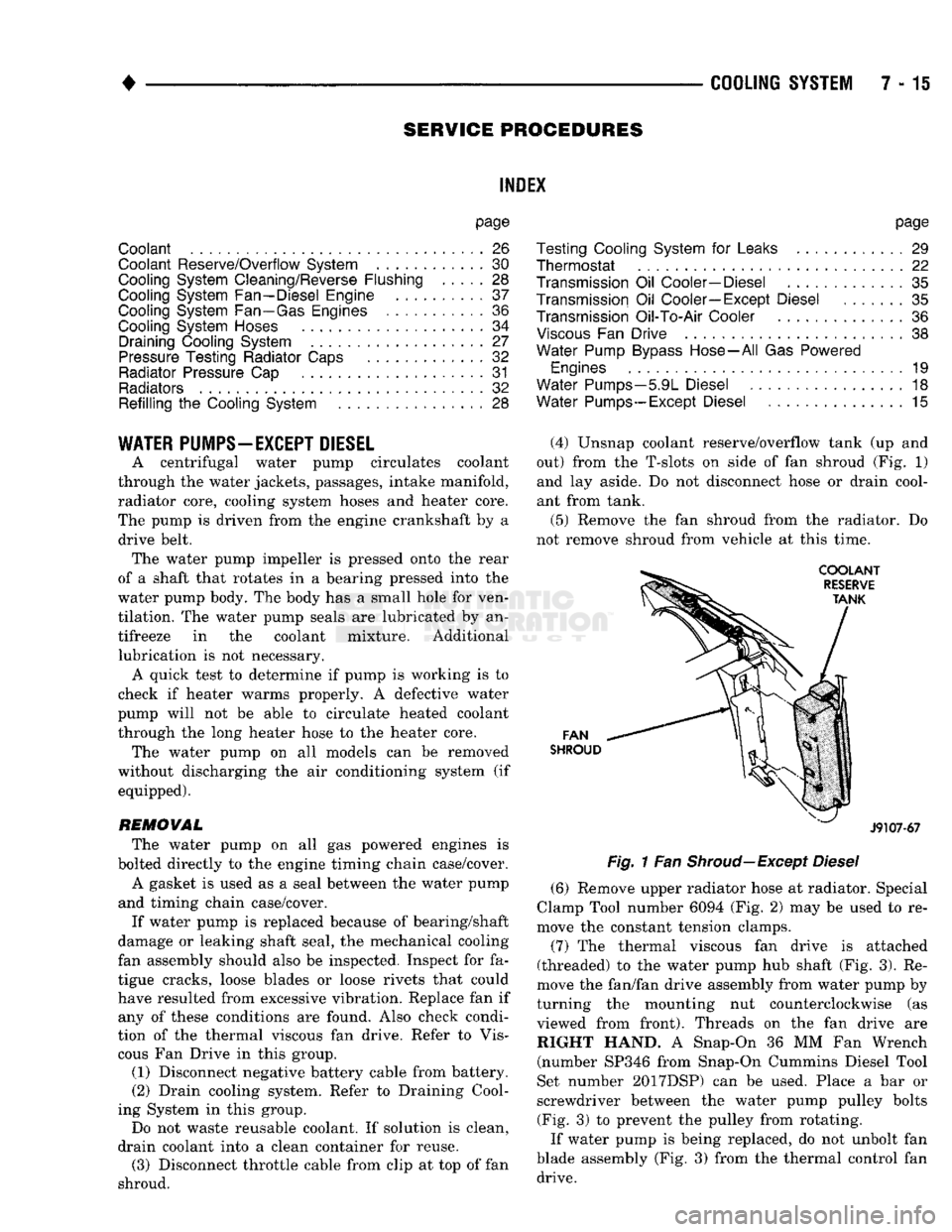
(4) Unsnap coolant reserve/overflow tank (up and
out) from the T-slots on side of fan shroud (Fig. 1) and lay aside. Do not disconnect hose or drain cool
ant from tank.
(5) Remove the fan shroud from the radiator. Do
not remove shroud from vehicle at this time.
FAN
SHROUD
J9107-67
Fig.
1 Fan
Shroud—Except
Diesel
(6) Remove upper radiator hose at radiator. Special
Clamp Tool number 6094 (Fig. 2) may be used to re
move the constant tension clamps.
(7) The thermal viscous fan drive is attached
(threaded) to the water pump hub shaft (Fig. 3). Re
move the fan/fan drive assembly from water pump by
turning the mounting nut counterclockwise (as viewed from front). Threads on the fan drive are RIGHT HAND. A Snap-On 36 MM Fan Wrench (number SP346 from Snap-On Cummins Diesel Tool
Set number 2017DSP) can be used. Place a bar or
screwdriver between the water pump pulley bolts (Fig. 3) to prevent the pulley from rotating.
If water pump is being replaced, do not unbolt fan
blade assembly (Fig. 3) from the thermal control fan drive.