1993 DODGE TRUCK clock
[x] Cancel search: clockPage 437 of 1502
8K
- 6
WINDSHIELD WIPER
AND
WASHER SYSTEMS
• INTERMITTENT WINDSHIELD WIPER FUNCTION
AND
SWITCH TESTING
PROCEDURES
INTERMITTENT
WIPER
FUNCTION
TESTING
PROCEDURES
The intermittent wipe and standard two speed mo
tors are identical. Refer to previous sections for diag
nosis of system problems which do not involve the
DELAY function. If problem occurs only in the DE LAY mode, the following tests are to be performed.
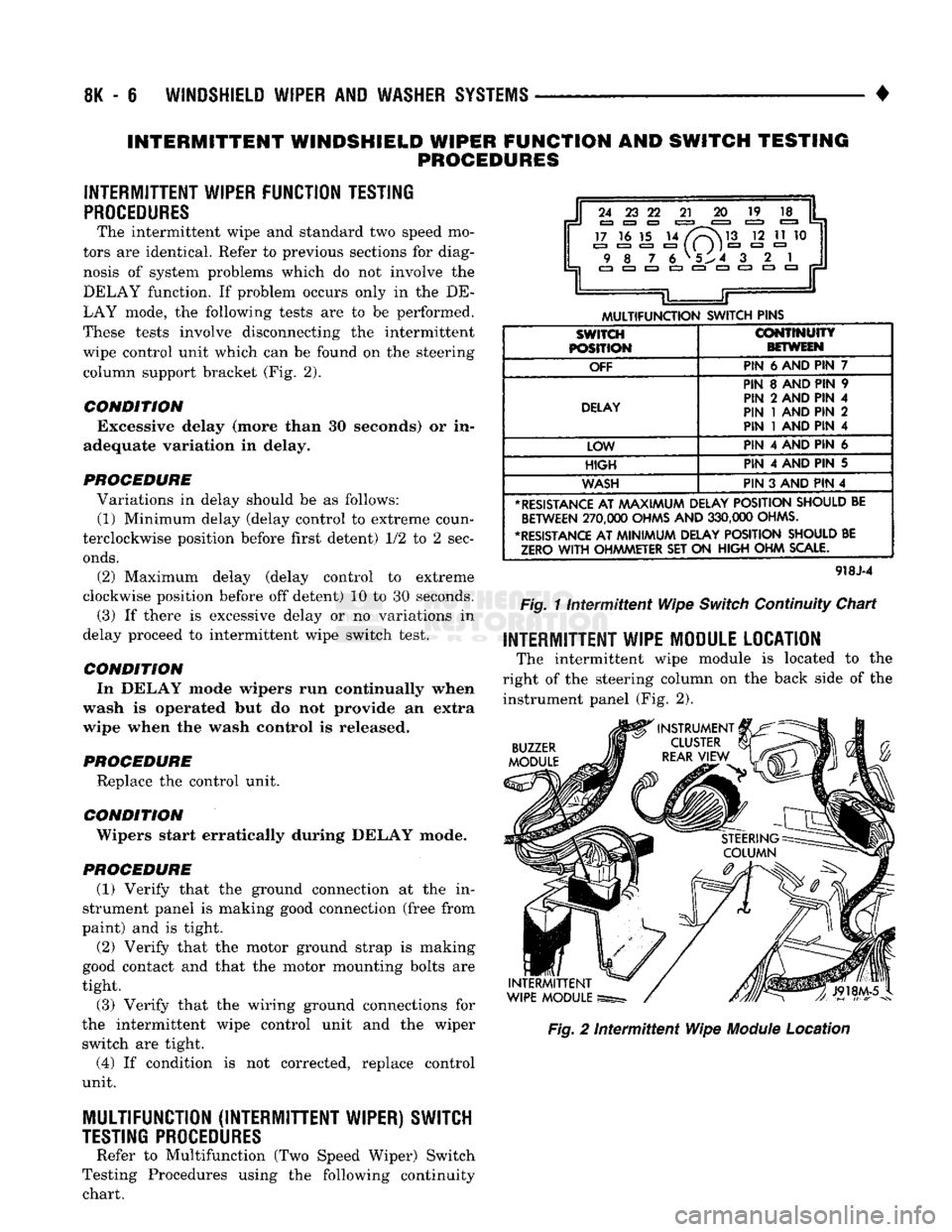
These tests involve disconnecting the intermittent wipe control unit which can be found on the steering column support bracket (Fig. 2).
CONDITION Excessive delay (more than 30 seconds) or in
adequate variation in delay.
PROCEDURE Variations in delay should be as follows: (1) Minimum delay (delay control to extreme coun
terclockwise position before first detent) 1/2 to 2 sec
onds.
(2) Maximum delay (delay control to extreme
clockwise position before off detent) 10 to 30 seconds.
(3) If there is excessive delay or no variations in
delay proceed to intermittent wipe switch test.
CONDITION In DELAY mode wipers run continually when
wash is operated but do not provide an extra
wipe when the wash control is released.
PROCEDURE Replace the control unit.
CONDITION ' Wipers start erratically during DELAY mode.
PROCEDURE (1) Verify that the ground connection at the in
strument panel is making good connection (free from
paint) and is tight.
(2) Verify that the motor ground strap is making
good contact and that the motor mounting bolts are
tight.
(3) Verify that the wiring ground connections for
the intermittent wipe control unit and the wiper switch are tight.
(4) If condition is not corrected, replace control
unit.
MULTIFUNCTION (INTERMITTENT WIPER) SWITCH
TESTING
PROCEDURES
Refer to Multifunction (Two Speed Wiper) Switch
Testing Procedures using the following continuity chart.
i
24 23 22
21 20 19
17 16 15 14
/V~\M3
12 11 10 9 8
7
6 V5^4 3
.
2 1
EZJ
CZ3 CZ3 C3 Jr
L
JT
MULTIFUNCTION
SWITCH
PINS
SWITCH
POSITION
CONTINUITY
BETWEEN
OFF
PIN
6 AND PIN 7
DELAY
PIN 8 AND PIN 9
PIN 2 AND PIN 4
PIN
1
AND PIN 2
PIN
1
AND PIN 4
LOW PIN 4 AND PIN 6
HIGH
PIN 4 AND PIN 5
WASH
PIN 3 AND PIN 4
*
RESISTANCE
AT
AAAXIMUM
DELAY
POSITION
SHOULD
BE
BETWEEN
270,000
OHMS
AND
330,000
OHMS.
•RESISTANCE
AT
MINIMUM
DELAY
POSITION
SHOULD
BE
ZERO
WITH
OHMMETER
SET ON
HIGH
OHM
SCALE.
918J-4
Fig.
11ntermittent
Wipe
Switch
Continuity Chart
INTERMITTENT WIPE MODULE LOCATION
The intermittent wipe module is located to the
right of the steering column on the back side of the instrument panel (Fig. 2).
BUZZER
MODULE
INTERMITTENT
WIPE
MODULE
Fig.
2
Intermittent
Wipe
Module
Location
Page 451 of 1502
8L
- 8
LAMPS
CONNECTOR
CUP
FRONT
LAMP
ASSEMBLY
LICENSE
PLATE
SCREW
LAMP
ASSEMBLY
LICENSE
PLATE
RR8LD24
Fig.
15
License
Plate
Lamps
-
Step
Bumper
TO
TAIL,
STOP,
TURN
SIG. AND
BACK
UP
LAMPS
LICENSE
PLATE
LICENSE
PLATE
LAMP
AND
LAMP
CONNECTOR
BRACKET
ASSEMBLY
J908L-74
Fig.
16
License
Plate
Lamp
Without Rear
Bumper
UNDERHOOD
LAMP
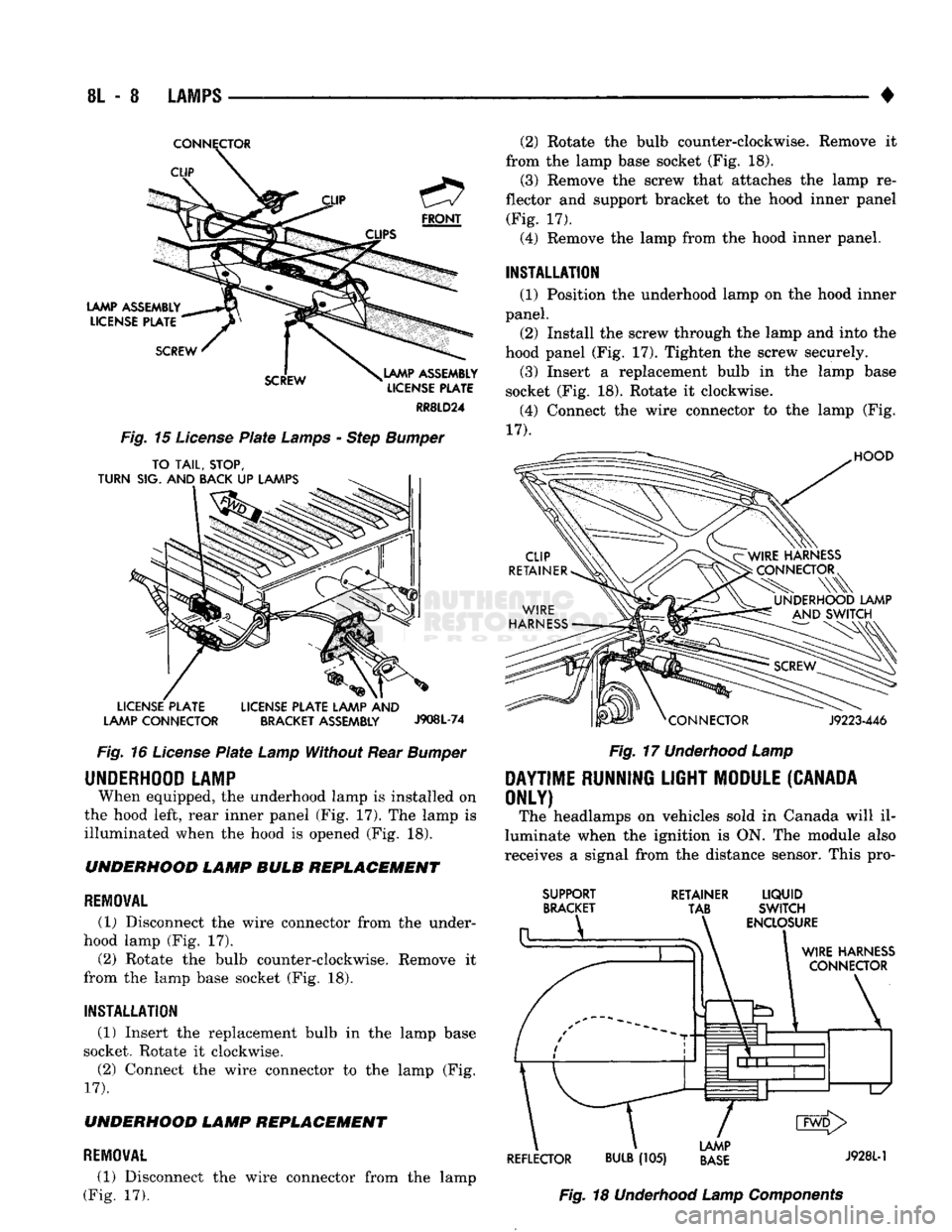
When equipped, the underhood lamp is installed on
the hood left, rear inner panel (Fig, 17). The lamp is
illuminated when the hood is opened (Fig. 18). UNDERHOOD LAMP BULB REPLACEMENT
REMOVAL
(1) Disconnect the wire connector from the under
hood lamp (Fig. 17).
(2) Rotate the bulb counter-clockwise. Remove it
from the lamp base socket (Fig. 18).
INSTALLATION
(1) Insert the replacement bulb in the lamp base
socket. Rotate it clockwise.
(2) Connect the wire connector to the lamp (Fig.
17).
UNDERHOOD LAMP REPLACEMENT
REMOVAL
(1) Disconnect the wire connector from the lamp
(Fig. 17). (2) Rotate the bulb counter-clockwise. Remove it
from the lamp base socket (Fig. 18). (3) Remove the screw that attaches the lamp re
flector and support bracket to the hood inner panel (Fig. 17).
(4) Remove the lamp from the hood inner panel.
INSTALLATION (1) Position the underhood lamp on the hood inner
panel. (2) Install the screw through the lamp and into the
hood panel (Fig. 17). Tighten the screw securely. (3) Insert a replacement bulb in the lamp base
socket (Fig. 18). Rotate it clockwise. (4) Connect the wire connector to the lamp (Fig.
17).
HOOD
J9223-446
Fig.
17
Underhood
Lamp
DAYTIME
RUNNING
LIGHT
MODULE
(CANADA
ONLY)
The headlamps on vehicles sold in Canada will il
luminate when the ignition is ON. The module also
receives a signal from the distance sensor. This pro-
SUPPORT
BRACKET RETAINER
LIQUID
TAB SWITCH
ENCLOSURE
WIRE
HARNESS
CONNECTOR
\
1
d1^—1—l
L/
CMD>
LAMP
REFLECTOR
BULB
(105)
BASE
J9281"1
Fig.
18
Underhood
Lamp
Components
Page 468 of 1502
POWER
MIRRORS
CONTENTS
page
SERVICE PROCEDURES
2
GENERAL
INFORMATION
Electrically-operated remote control mirrors are
available as an option on D-body vehicles. The mir
rors are controlled by a single switch assembly lo
cated on the instrument panel to the right of the
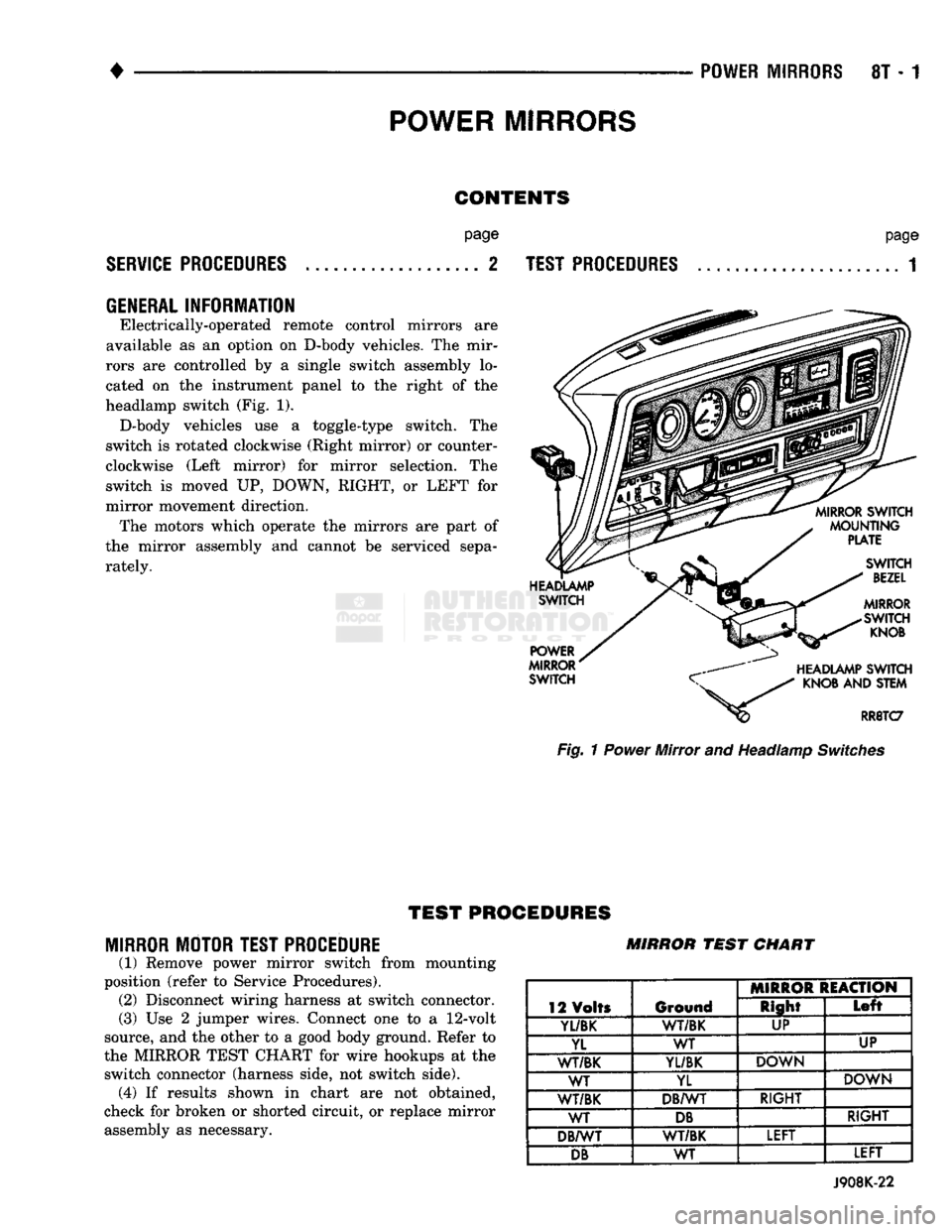
headlamp switch (Fig. 1). D-body vehicles use a toggle-type switch. The
switch is rotated clockwise (Right mirror) or counter
clockwise (Left mirror) for mirror selection. The
switch is moved UP, DOWN, RIGHT, or LEFT for
mirror movement direction. The motors which operate the mirrors are part of
the mirror assembly and cannot be serviced sepa
rately.
page
TEST PROCEDURES
...................... 1 Fig. 1 Power Mirror and Headlamp Switches
TEST
PROCEDURES
MIRROR MOTOR TEST PROCEDURE
(1) Remove power mirror switch from mounting
position (refer to Service Procedures). (2) Disconnect wiring harness at switch connector.
(3) Use 2 jumper wires. Connect one to a
12-volt
source, and the other to a good body ground. Refer to
the MIRROR TEST CHART for wire hookups at the switch connector (harness side, not switch side), (4) If results shown in chart are not obtained,
check for broken or shorted circuit, or replace mirror assembly as necessary. MIRROR
TEST
CHART
12 Volts Ground MIRROR REACTION
12 Volts Ground Right
Left
Yl/BK
1
WT/BK UP
YL WT UP
WT/BK
YL/BK
DOWN
WT YL DOWN
WT/BK DB/WT RIGHT
WT
DB
RIGHT
DB/WT WT/BK LEFT
DB
WT LEFT
J908K-22
Page 474 of 1502
•
CHIME/BUZZER
WARNING
SYSTEMS
8U - 3
KEY-IN
SWITCH REPLACEMENT
REMOVAL
(1) Disconnect negative cable from battery.
(2) Tilt column only—remove tilt lever (counter
clockwise).
(3) Carefully remove both upper and lower steer
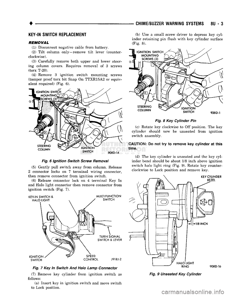
ing column covers. Requires removal of 3 screws (torx T-20). (4) Remove 3 ignition switch mounting screws
(tamper proof torx bit Snap On TTXR15A2 or equiv
alent required) (Fig. 6).
STEERING
COLUMN IGNITION
SWITCH
908D-14
Fig.
6 Ignition
Switch
Screw
Removal
(5) Gently pull switch away from column. Release
2 connector locks on 7 terminal wiring connector,
then remove connector from ignition switch.
(6) Release connector lock on 4 terminal Key In
and Halo light connector then remove connector from
ignition switch (Fig. 7).
KEY-IN SWITCH
&
HALO
LIGHT
MULTIFUNCTION
SWITCH
IGNITION SWITCH TURN SIGNAL
SWITCH
&
LEVER
SPEED
CONTROL
J918J-2
Fig.
7 Key In
Switch
And Halo
Lamp
Connector
(7) Remove key cylinder from ignition switch as
follows:
(a) Insert key in ignition switch and move switch
to Lock position. (b) Use a small screw driver to depress key cyl
inder retaining pin flush with key cylinder surface (Fig. 8).
IGNITION SWITCH MOUNTING
SCREWS
(3)
STEERING
COLUMN IGNITION
SWITCH
938 D-1
Fig.
8 Key Cylinder Pin
(c) Rotate key clockwise to Off position. The key
cylinder should now be unseated from ignition
switch assembly.
CAUTION:
Do not try to remove key cylinder at this
time.
(d) The key cylinder is unseated and the key cyl
inder bezel should be about 1/8 inch above ignition
switch halo light ring (Fig. 9). Rotate key counter
clockwise to Lock position and remove key.
KEY
CYLINDER
BEZEL
HALO
LIGHT
RING
908D-16
Fig.
9 Unseated Key Cylinder
Page 475 of 1502
8U
- 4
CHIME/BUZZER WARNING
SYSTEMS
•
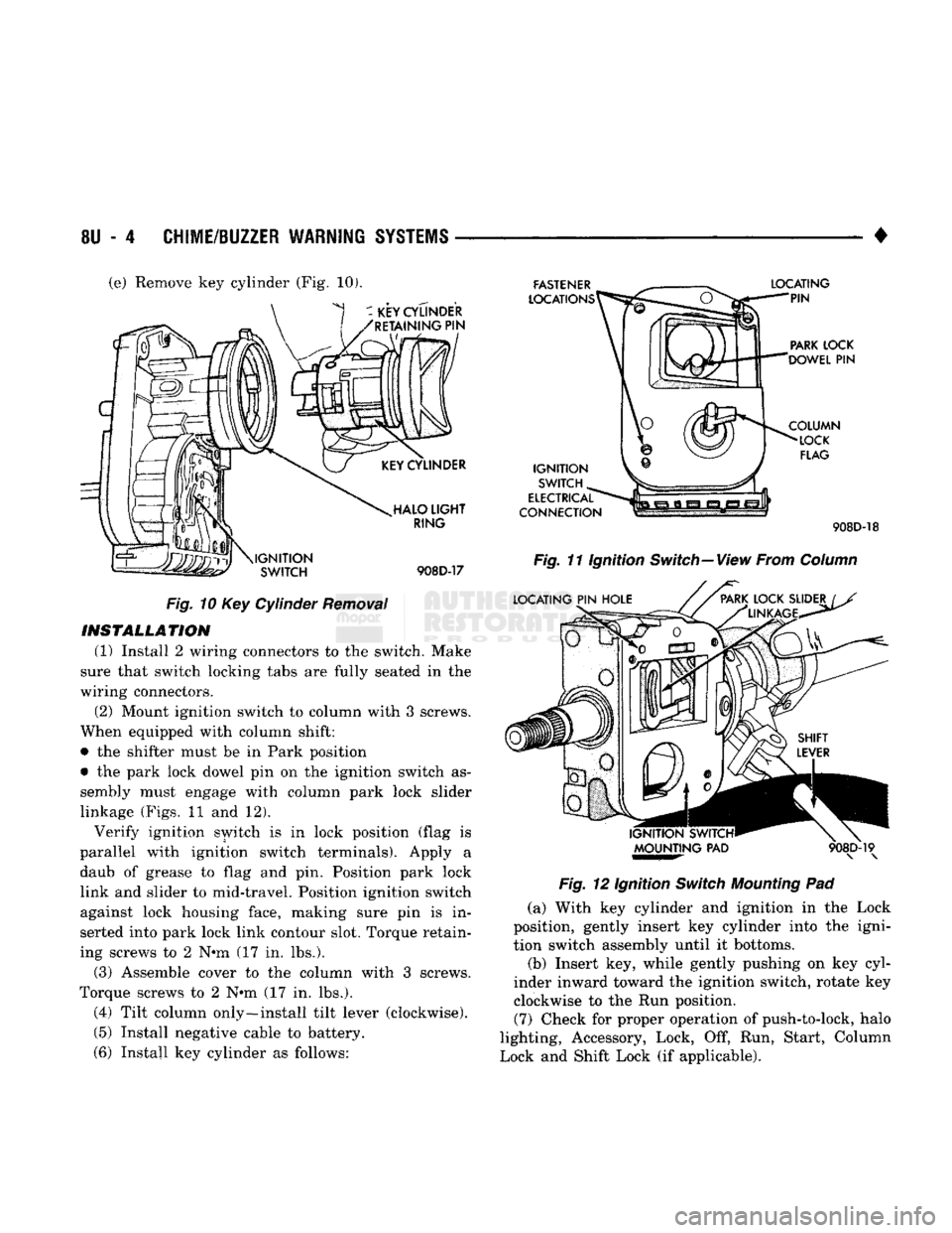
(e) Remove key cylinder (Fig, 10).
Fig.
10 Key Cylinder
Removal
INSTALLATION
(1) Install 2 wiring connectors to the switch. Make
sure that switch locking tabs are fully seated in the
wiring connectors.
(2) Mount ignition switch to column with 3 screws.
When equipped with column shift:
• the shifter must be in Park position
• the park lock dowel pin on the ignition switch as
sembly must engage with column park lock slider
linkage (Figs. 11 and 12). Verify ignition switch is in lock position (flag is
parallel with ignition switch terminals). Apply a daub of grease to flag and pin. Position park lock link and slider to mid-travel. Position ignition switch
against lock housing face, making sure pin is in
serted into park lock link contour slot. Torque retain
ing screws to 2 N*m (17 in. lbs.).
(3) Assemble cover to the column with 3 screws.
Torque screws to 2 N*m (17 in. lbs.).
(4) Tilt column only—install tilt lever (clockwise). (5) Install negative cable to battery.
(6) Install key cylinder as follows: 908D-18
Fig.
11 Ignition Switch—View From
Column
Fig.
12 Ignition
Switch
Mounting
Pad
(a) With key cylinder and ignition in the Lock
position, gently insert key cylinder into the igni
tion switch assembly until it bottoms.
(b) Insert key, while gently pushing on key cyl
inder inward toward the ignition switch, rotate key clockwise to the Run position. (7) Check for proper operation of push-to-lock, halo
lighting, Accessory, Lock, Off, Run, Start, Column
Lock and Shift Lock (if applicable).
Page 476 of 1502
•
WIRING DIAGRAMS
8W
- 1
CONTENTS
page page
COMPONENT IDENTIFICATION
.............
9
SPLICE LOCATIONS
29
GENERAL
INFORMATION
1
WIRING DIAGRAMS AD-BODY
37
GENERAL
INFORMATION
INDEX
page
Circuit
Identification
2
Component
Identification
3
Connectors
3
Fusible Links
3
Harness
Repair
3
Locating
A
System
or
Component
2
page
Secondary
Ignition
Wiring
1
Splice Locations
3
Symbols
and
Fuses
5
Troubleshooting
Wiring
Problems
3
Wire Code
Identification
2
Wiring
Diagram Sheets
and
Indexes
1
The wiring diagrams contain
the
latest information
available
at
time
of
publication. Throughout
out
this
group references
may
be
made
to a
particular vehicle
by letter
or
number designation.
A
chart showing
the
breakdown
of
these designations
is
included
in the
Introduction Section
of
this service manual.
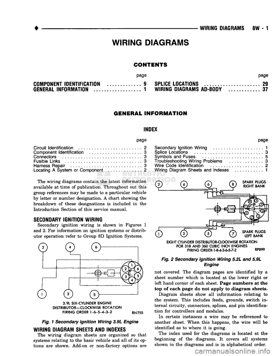
SECONDARY
IGNITION WIRING
Secondary ignition wiring
is
shown
in
Figures
1
and 2.
For
information
on
ignition systems
or
distrib
utor operation refer
to
Group
8D
Ignition Systems.
SPARK
PLUGS
RIGHT
BANK
3.9L
SIX-CYLINDER
ENGINE
DISTRIBUTOR—CLOCKWISE
ROTATION
FIRING
ORDER
1-6-5-4-3-2
RN755
Fig.
1
Secondary
Ignition Wiring 3.9L
Engine
WIRING DIAGRAM SHEETS AND INDEXES
The wiring diagram sheets
are
organized
so
that
systems relating
to the
basic vehicle
and all of
its op
tions
are
shown. Add-on
or
non-factory options
are
SPARK
PLUGS
LEFT
BANK
EIGHT
CYLINDER
DISTRIBUTOR-CLOCKWISE
ROTATION
FOR
318
AND
360
CUBIC
INCH
ENGINES
FIRING
ORDER-1-8^-3-63-7-2 RP899 Fig.
2
Secondary
Ignition Wiring 5.2L and 5.9L
Engine
not covered.
The
diagram pages
are
identified
by a
sheet number which
is
located
at the
lower right
or
left hand corner
of
each sheet. Page numbers
at the
top
of
each page
do not
apply
to
diagram sheets.
Diagram sheets show
all
information relating
to
the system. This includes feeds, grounds, switch
in
ternal circuity, connectors, splices,
and
pin
identifica
tion
for
controllers
and
modules.
In certain instances
a
wire
may be
referenced
to
another sheet. When this happens,
the
wire will
be
identified
as to
where
it is
going.
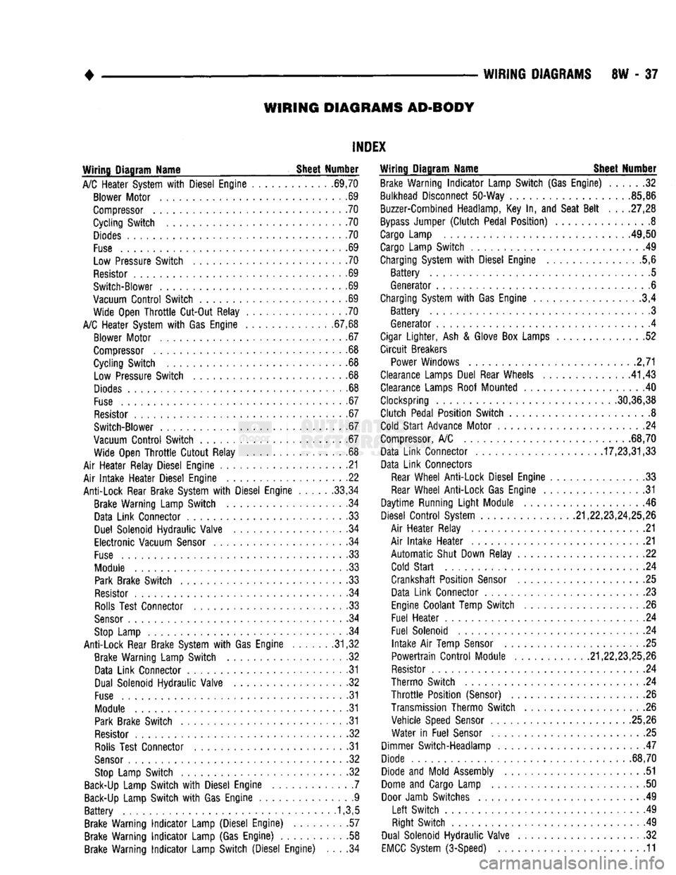
The index used
for the
diagrams
is
located
at the
beginning
of the
diagrams.
It
covers
all
systems shown
in the
diagrams
and is in
alphabetical order.
WIRING
DIAGRAMS
Page 482 of 1502
CAVITY
FUSE/
COLOR ITEMS FUSED
CAVITY
FUSE/
COLOR ITEMS FUSED
10
11
12
13 2 AMP
GY VEHICLE SPEED CONTROL
5 AMP TN
GAUGES,
BRAKE WARNING LAMP, SEAT BELT WARNING
LAMP, BUZZER, LOW OIL LAMP, CHECK ENGINE LAMP,
ANTI-LOCK LAMP, TAILGATE OPEN LAMP, 4WD LAMP, O/D MODULE, LOW FUEL LAMP,
WAIT
TO START LAMP
WATER-IN-FUEL LAMP 14
3 AMP
VT
20 AMP YL BACK-UP LAMP, HEATED REAR WINDOW
15 10 AMP
RD
ILLUMINATION
LAMPS, A/C HEATER LAMP, ASH
RECEIVER LAMP, RADIO LAMP, TRANSMISSION
OVERDRIVE SWITCH LAMP, TACHOMETER LAMP, HEATED REAR WINDOW SWITCH LAMP.
RADIO AND CLOCK MEMORY, POWER MIRRORS, GLOVE BOX LAMP, DOME LAMP, READING LAMP, MAP LAMP,
CARGO LAMP,
IGNITION
SWITCH LAMP, UNDERHOOD LAMP
20 AMP YL FUSE CAVITY #14,
TAIL
LAMPS, PARKING LAMPS, SIDE
AAARKER
LAMPS, LICENSE LAMPS, FRONT AND REAR CLEARANCE LAMPS, RADIO INTENSITY, HORNS
20 AMP YL STOP LAMPS, KEY-IN & HEADLAMP ON BUZZER, RWAL
MODULE 30 AMP
CIRCUIT
BREAKER
TURN
SIGNAL
FLASHER 20 AMP
YL POWER DOOR LOCKS
15 AMP
BL
CIGAR LIGHTER
10 AMP RD RADIO AND CLOCK
20 AMP YL
TURN
SIGNALS, TACHOMETER PROVISION,
RWAL MODULE
20 AMP YL WINDSHIELD WIPERS
30 AMP LG A/C - HEATER BLOWER MOTOR
30 AMP
C/BRKR
POWER WINDOWS
20 AMP YL HAZARD FLASHER
AMPS
FUSE
COLOR
2 GY GRAY
3 VT
VIOLET
5 TN
TAN
10 RD
RED
15
BL
BLUE
20 YL YELLOW
30 LG
LIGHT
GREEN HAZARD
FLASHER
J938W-94
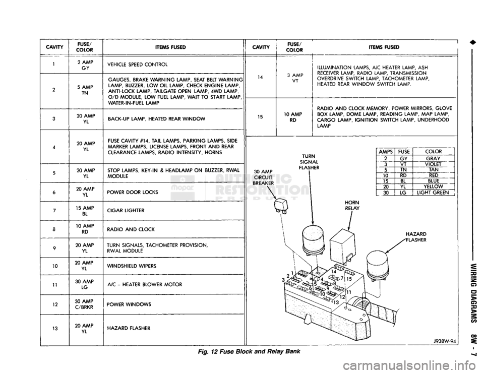
Fig. 12 Fuse Block and
Relay
Bank
Page 512 of 1502
WIRING
DIAGRAMS
8W
- 37
WIRING DIAGRAMS AD-BODY
INDEX
Wiring Diagram Name Sheet Number
A/C
Heater System
with
Diesel Engine ............ .69,70 Blower Motor
. .69
Compressor
.70
Cycling Switch
.70
Diodes
70
Fuse
69
Low Pressure Switch
70
Resistor
. 69
Switch-Blower
. 69
Vacuum
Control
Switch
.69
Wide Open
Throttle
Cut-Out Relay
70
A/C
Heater System
with Gas
Engine .67,68 Blower Motor
.67
Compressor
.68
Cycling Switch
68
Low Pressure Switch
.68
Diodes
. .68
Fuse
. .67
Resistor
67
Switch-Blower
67
Vacuum
Control
Switch
.67
Wide Open
Throttle
Cutout Relay
68
Air Heater Relay Diesel Engine
.21
Air
Intake
Heater Diesel Engine
22
Anti-Lock Rear Brake System
with
Diesel Engine
.....
.33,34 Brake Warning Lamp Switch
34
Data Link Connector
33
Duel Solenoid Hydraulic Valve
34
Electronic Vacuum
Sensor
.34
Fuse
33
Module
.33
Park
Brake Switch
.33
Resistor
34
Rolls
Test Connector
33
Sensor
34
Stop
Lamp
34
Anti-Lock Rear Brake System
with Gas
Engine .31,32 Brake Warning Lamp Switch
.32
Data Link Connector
. .31
Dual Solenoid Hydraulic Valve
32
Fuse
31
Module
31
Park
Brake Switch
.31
Resistor
32
Rolls
Test Connector
31
Sensor
32
Stop
Lamp Switch
32
Back-Up
Lamp Switch
with
Diesel Engine
.7
Back-Up
Lamp Switch
with Gas
Engine
.9
Battery
.1,3,5
Brake Warning
Indicator
Lamp (Diesel Engine)
.57
Brake Warning
Indicator
Lamp
(Gas
Engine)
58
Brake Warning
Indicator
Lamp Switch (Diesel Engine)
. . . .34
Wiring Diagram Name Sheet Number
Brake Warning
Indicator
Lamp Switch
(Gas
Engine)
32
Bulkhead Disconnect 50-Way .85,86
Buzzer-Combined Headlamp,
Key In, and
Seat
Belt
. . .
.27,28
Bypass
Jumper
(Clutch
Pedal Position)
8
Cargo
Lamp .49,50
Cargo
Lamp Switch
49
Charging System
with
Diesel Engine ..............
.5,6
Battery
5
Generator
. .6
Charging System
with
Gas Engine
.3,4
Battery
3
Generator
, . .4
Cigar
Lighter,
Ash &
Glove
Box
Lamps
52
Circuit
Breakers Power Windows
2,71
Clearance Lamps Duel Rear Wheels
.
.41,43 Clearance Lamps Roof Mounted
40
Clockspring 30,36,38
Clutch Pedal Position Switch
.8
Cold
Start
Advance Motor
24
Compressor,
A/C
68,70 Data Link Connector 17,23,31,33
Data Link Connectors
Rear
Wheel Anti-Lock Diesel Engine
.33
Rear
Wheel Anti-Lock Gas Engine
31
Daytime Running
Light
Module
46
Diesel
Control
System .21,22,23,24,25,26
Air Heater Relay
. .21
Air
Intake
Heater
21
Automatic
Shut Down Relay
22
Cold
Start
24
Crankshaft Position
Sensor
. .25
Data Link Connector
. .23
Engine
Coolant Temp Switch
.26
Fuel Heater
24
Fuel Solenoid
24
Intake
Air
Temp
Sensor
25
Powertrain
Control
Module 21,22,23,25,26
Resistor
.24
Thermo Switch
24
Throttle
Position (Sensor)
26
Transmission Thermo Switch
. . .26
Vehicle Speed
Sensor
25,26 Water
in
Fuel
Sensor
.25
Dimmer Switch-Headlamp
. .47
Diode 68,70
Diode
and
Mold Assembly
51
Dome
and
Cargo Lamp
50
Door
Jamb Switches
49
Left
Switch
.49
Right Switch
49
Dual Solenoid Hydraulic Valve
.32
EMCC
System (3-Speed)
. .11