1993 DODGE TRUCK clock
[x] Cancel search: clockPage 287 of 1502
7 - 16
COOLING
SYSTEM
•
HOSE
CLAMP
HOSE
J9207-36
Fig.
2
Hose
Clamp
Tool
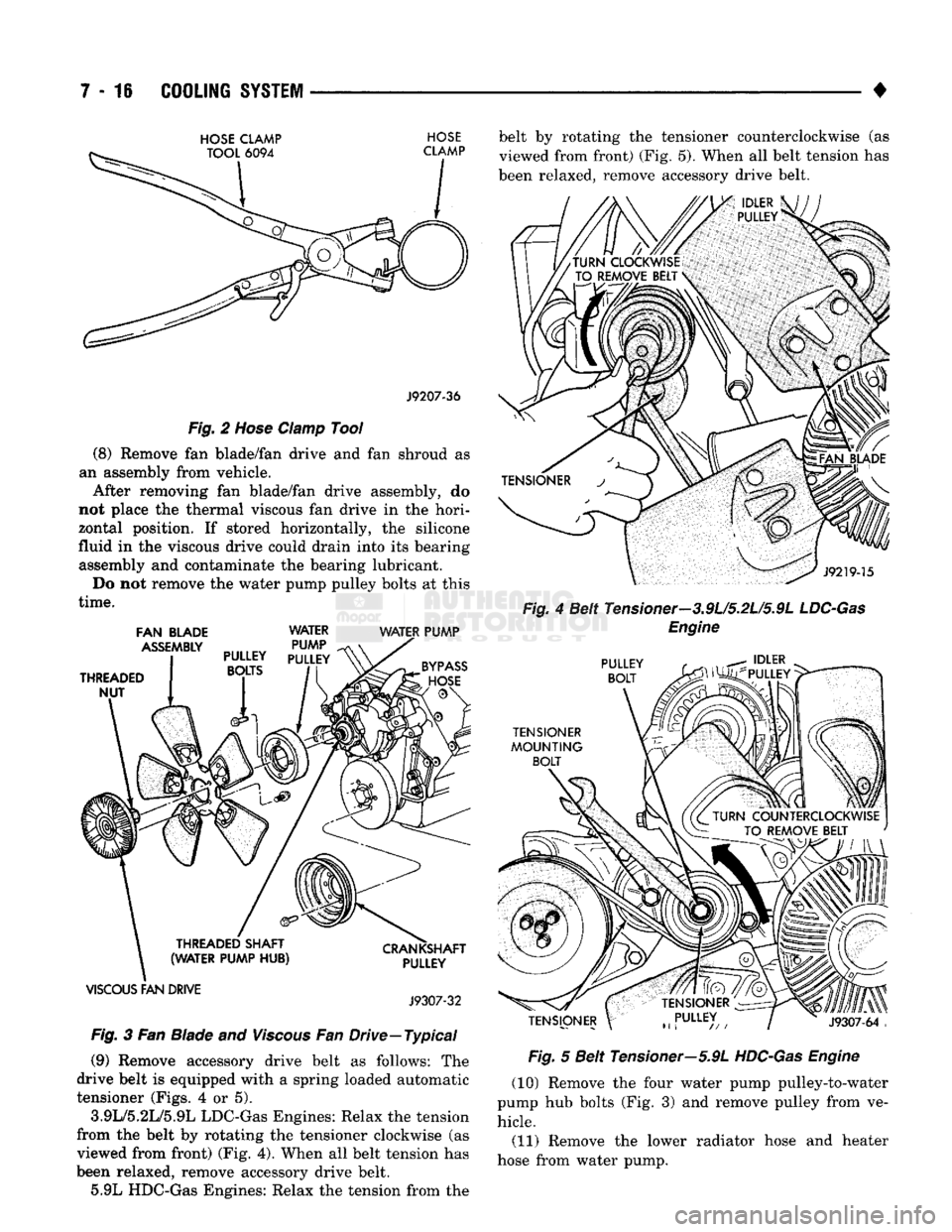
(8) Remove fan blade/fan drive and fan shroud as
an assembly from vehicle. After removing fan blade/fan drive assembly, do
not place the thermal viscous fan drive in the hori
zontal position. If stored horizontally, the silicone
fluid in the viscous drive could drain into its bearing assembly and contaminate the bearing lubricant.
Do not remove the water pump pulley bolts at this
time.
FAN
BLADE
WATER WATER
PUMP
VISCOUS
FAN
DRIVE
J9307-32
Fig.
3 Fan Blade and
Viscous
Fan Drive—Typical (9) Remove accessory drive belt as follows: The
drive belt is equipped with a spring loaded automatic
tensioner (Figs. 4 or 5).
3.9L/5.2L/5.9L LDC-Gas Engines: Relax the tension
from the belt by rotating the tensioner clockwise (as
viewed from front) (Fig. 4). When all belt tension has
been relaxed, remove accessory drive belt. 5.9L HDC-Gas Engines: Relax the tension from the belt by rotating the tensioner counterclockwise (as
viewed from front) (Fig. 5). When all belt tension has
been relaxed, remove accessory drive belt.
Fig.
4 Belt Tensioner—3.9L/5.2L/5.9L
LDC-Gas
Engine
Fig.
5 Belt Tensioner—5.9L
HDC-Gas
Engine
(10) Remove the four water pump pulley-to-water
pump hub bolts (Fig. 3) and remove pulley from ve hicle.
(11) Remove the lower radiator hose and heater
hose from water pump.
Page 303 of 1502
7 - 32
COOLING
SYSTEM
• pressure. It also maintains vacuum during coolant
cool-down allowing coolant to return from reserve/
overflow tank.
RADIATOR
CAP-TO-FILLER
NECK
SEAL-PRESSURE RELIEF CHECK The pressure cap upper gasket (seal) pressure relief
can be tested by removing overflow hose from radia
tor filler neck nipple. Attach hose of pressure tester
tool 7700 or equivalent to nipple. It will be necessary
to disconnect hose from its adapter for filler neck.
Pump air into radiator. The pressure cap upper gas
ket should relieve at 69-124 kPa (10-18 psi) and hold
pressure at a minimum of 55 kPa (8 psi).
WARNING;
THE
WARNING WORDS
-DO NOT
OPEN HOT—
ON
RADIATOR PRESSURE CAP, ARE
A SAFETY PRECAUTION. WHEN
HOT,
PRESSURE BUILDS
UP IN
COOLING SYSTEM.
TO
PREVENT
SCALDING
OR
INJURY, RADIATOR
CAP
SHOULD NOT
BE
REMOVED WHILE SYSTEM
IS HOT
AND/OR UNDER
PRESSURE.
Do not remove radiator cap at any time except for
the following purposes: • Check and adjust antifreeze freeze point
• Refill system with new antifreeze
• Conducting service procedures
• Checking for vacuum leaks
WARNING;
IF
VEHICLE HAS BEEN RUN RECENTLY,
WAIT
AT
LEAST
15
MINUTES BEFORE REMOVING
RADIATOR CAP.
WITH
A
RAG, SQUEEZE RADIA
TOR UPPER HOSE
TO
CHECK
IF
SYSTEM
IS UN
DER
PRESSURE.
PLACE
A RAG
OVER
CAP AND
WITHOUT
PUSHING
CAP
DOWN, ROTATE
IT
COUNTER-CLOCKWISE
TO
FIRST STOP. ALLOW FLUID
TO
ESCAPE THROUGH
THE
COOLANT RE
SERVE/OVERFLOW HOSE
INTO
RESERVE/OVER FLOW TANK. SQUEEZE RADIATOR UPPER HOSE
TO DETERMINE WHEN PRESSURE HAS BEEN RE
LEASED.
WHEN COOLANT AND STEAM STOP BE
ING PUSHED
INTO
TANK AND SYSTEM PRESSURE
DROPS,
REMOVE RADIATOR CAP COMPLETELY.
PRESSURE
TESTING
RADIATOR
CAPS
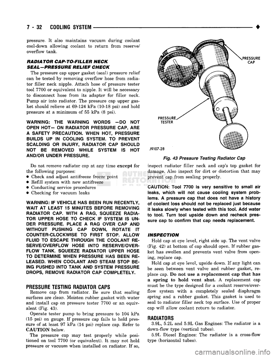
Remove cap from radiator. Be sure that sealing
surfaces are clean. Moisten rubber gasket with water
and install cap on pressure tester 7700 or an equiv
alent (Fig. 43). Operate tester pump to bring pressure to 104 kPa
(15 psi) on gauge. If pressure cap fails to hold pres
sure of at least 97 kPa (14 psi) replace cap. Refer to
CAUTION below. The pressure cap may test properly while posi
tioned on tool 7700 (or equivalent). It may not hold
pressure or vacuum when installed on radiator. If so,
Fig.
43
Pressure
Testing Radiator Cap
inspect radiator filler neck and cap's top gasket for
damage. Also inspect for dirt or distortion that may
prevent cap from sealing properly.
CAUTION:
Tool
7700
is
very
sensitive
to
small
air
leaks,
which
will
not
cause
cooling
system
prob
lems.
A
pressure
cap
that
does
not
have
a
history
of
coolant
loss
should
not be
replaced
just
because
it
leaks
slowly
when
tested
with
this
tool.
Add
water
to
tool.
Turn
tool
upside
down
and
recheck
pres
sure
cap to
confirm
that
cap
needs
replacement.
INSPECTION
Hold cap at eye level, right side up. The vent valve
(Fig. 42) at bottom of cap should open. If rubber gas
ket has swollen and prevents vent valve from open ing, replace cap.
Hold cap at eye level, upside down. If any light can
be seen between vent valve and rubber gasket, re place cap. Do not use a replacement cap that has a spring to hold vent shut. A replacement cap
must be the type designed for a coolant reserve/over
flow system with a completely sealed diaphragm spring and a rubber gasket. This gasket is used to
seal to radiator filler neck top surface. Use of proper
cap will allow coolant return to radiator.
RADIATORS
3.9L, 5.2L and 5.9L Gas Engines: The radiator is a
down-flow type (vertical tubes). 5.9L Diesel Engines: The radiator is a cross-flow
type (horizontal tubes).
Page 305 of 1502
7 - 34
COOLING SYSTEM
•
WARNING;
DO NOT
REMOVE
THE
CYLINDER
BLOCK DRAIN PLUGS
OR
LOOSEN
THE
RADIATOR
DRAINCOCK
WITH
THE
SYSTEM
HOT AND
UNDER
PRESSURE.
SERIOUS BURNS FROM COOLANT
CAN OCCUR.
(2) Drain the cooling system. Refer to Draining
Cooling System in this group. (3) Remove hose clamps and hoses from radiator.
Remove coolant reserve/overflow tank hose from ra diator filler neck nipple.
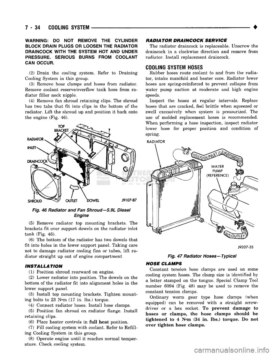
(4) Remove fan shroud retaining clips. The shroud
has two tabs that fit into clips in the bottom of the radiator. Lift the shroud up and position it back onto
the engine (Fig. 46).
Fig. 46 Radiator and Fan
Shroud—5.9L
Diesel Engine
(5) Remove radiator top mounting brackets. The
brackets fit over support dowels on the radiator inlet
tank (Fig. 46).
(6) The bottom of the radiator has two dowels that
fit into holes in the lower support panel. Taking care not to damage radiator cooling fins or tubes, lift ra
diator straight up out of engine compartment
INSTALLATION (1) Position shroud rearward on engine.
(2) Lower radiator into position. The dowels on the
bottom of the radiator fit into alignment holes in the lower support panel.
(3) Install top mounting brackets. Tighten mount
ing bolts to 23 N*m (17 in. lbs.) torque. (4) Connect radiator hoses. Install hose clamps.
(5) Position fan shroud on radiator flange. Install
retaining clips. (6) Place heater controls in full heat position.
(7) Fill cooling system with coolant. Refer to Refill
ing Cooling System in this group.
(8) Operate engine until it reaches normal temper
ature. Check cooling system. RADIATOR DRAINCOCK SERVICE
The radiator draincock is replaceable. Unscrew the
draincock in a clockwise direction and remove from
radiator. Install replacement draincock.
COOLING SYSTEM HOSES
Rubber hoses route coolant to and from the radia
tor, intake manifold and heater core. Radiator lower
hoses are spring-reinforced to prevent collapse from
water pump suction at moderate and high engine speeds. Inspect the hoses at regular intervals. Replace
hoses that are cracked, feel brittle when squeezed or swell excessively when system is pressurized. The
use of molded replacement hoses is recommended.
When performing a hose inspection, inspect radiator lower hose for proper position and condition of spring.
RADIATOR
J9207-35
Fig. 47 Radiator Hoses—Typical
HOSE CLAMPS Constant tension hose clamps are used on some
cooling system hoses. The clamp size is identified by a letter stamped on the tongue. Special Clamp Tool
number 6094 (Fig. 48) may be used to remove the
constant tension clamps.
Ordinary worm gear type hose clamps (when
equipped) can be removed with a straight screw
driver or a hex socket. To prevent damage to
hoses or clamps, the hose clamps should be
tightened to 4 N«m (34 in. lbs.) torque. Do not
over tighten hose clamps.
Page 307 of 1502
7 - 36
COOLING
SYSTEM
• (4) Connect coolant hoses to cooler.
(5)
Connect battery cable to battery.
(6)
Fill cooling system. Refer to Refilling Cooling
System in this section. (7) Check transmission oil level and fill as neces
sary.
TRANSMISSION
OIL/TO-AIR
COOLER
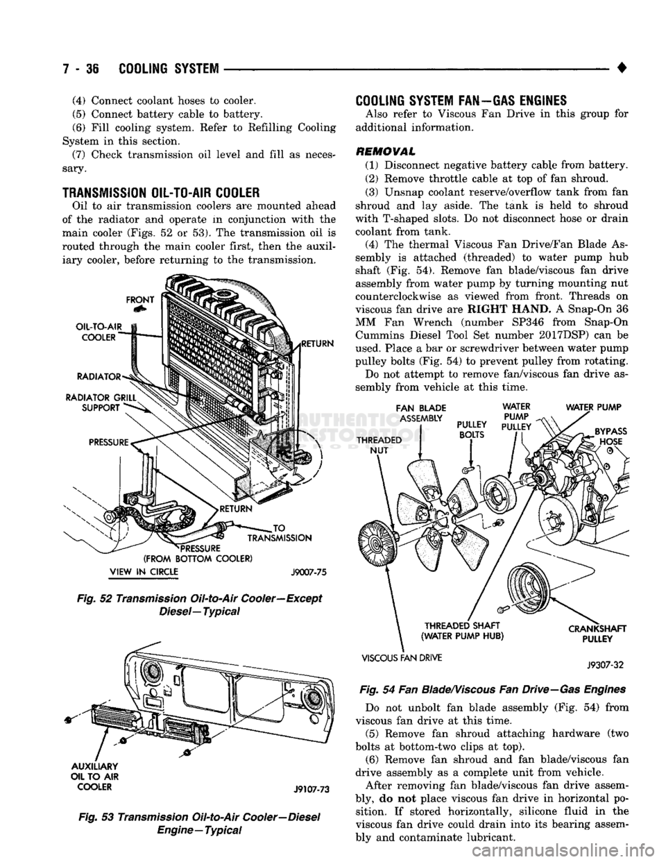
Oil to air transmission coolers are mounted ahead
of the radiator and operate in conjunction with the
main cooler (Figs, 52 or 53). The transmission oil is
routed through the main cooler first, then the auxil iary cooler, before returning to the transmission.
FRONT
OIL-TO-AIR
COOLER
RADIATOR
RADIATOR GRILL SUPPORT RETURN JO
_
TRANSMISSION
*
PRESSURE
(FROM BOTTOM COOLER)
VIEW
IN
CIRCLE J9007-75 Fig.
52
Transmission
Oil-to-Air Cooler—Except
Diesel—
Typical
AUXILIARY
OIL TO AIR
COOLER
J9107-73
Fig.
53
Transmission
Oil-to-Air
Cooler—Diesel
Engine—Typical
COOLING
SYSTEM FAN—GAS ENGINES
Also refer to Viscous Fan Drive in this group for
additional information.
REMOVAL (1) Disconnect negative battery cable from battery.
(2) Remove throttle cable at top of fan shroud.
(3) Unsnap coolant reserve/overflow tank from fan
shroud and lay aside. The tank is held to shroud
with T-shaped slots. Do not disconnect hose or drain
coolant from tank.
(4) The thermal Viscous Fan Drive/Fan Blade As
sembly is attached (threaded) to water pump hub
shaft (Fig. 54). Remove fan blade/viscous fan drive
assembly from water pump by turning mounting nut
counterclockwise as viewed from front. Threads on
viscous fan drive are RIGHT HAND. A Snap-On 36
MM Fan Wrench (number SP346 from Snap-On Cummins Diesel Tool Set number 2017DSP) can be
used. Place a bar or screwdriver between water pump
pulley bolts (Fig. 54) to prevent pulley from rotating. Do not attempt to remove fan/viscous fan drive as
sembly from vehicle at this time.
FAN BLADE
ASSEMBLY
THREADED NUT WATER
PUMP
PULLEY
PULLEY
BOLTS
WATER PUMP
THREADED SHAFT
(WATER PUMP HUB)
VISCOUS
FAN DRIVE CRANKSHAFT
PULLEY
J9307-32
Fig.
54 Fan
Blade/Viscous
Fan
Drive—Gas
Engines
Do not unbolt fan blade assembly (Fig. 54) from
viscous fan drive at this time.
(5) Remove fan shroud attaching hardware (two
bolts at bottom-two clips at top). (6) Remove fan shroud and fan blade/viscous fan
drive assembly as a complete unit from vehicle.
After removing fan blade/viscous fan drive assem
bly, do not place viscous fan drive in horizontal po sition. If stored horizontally, silicone fluid in the
viscous fan drive could drain into its bearing assem
bly and contaminate lubricant.
Page 308 of 1502
•
COOLING
SYSTEM
7 - 37
CAUTION:
Do not
remove
water
pump pulley-to-wa
ter
pump
bolts
(Fig. 54), This
pulley
is
under spring
tension.
(7) Remove four bolts securing fan blade assembly
to viscous fan drive (Fig. 54).
INSPECTION The fan cannot be repaired. If fan is damaged, it
must be replaced. Inspect fan as follows:
(1) Remove fan blade and viscous fan drive as an
assembly from the engine. Refer to preceding Re
moval procedure.
(2) Remove fan blade assembly from viscous fan
drive unit (four bolts).
(3) Lay fan on a flat surface with leading edge fac
ing down. With tip of blade touching flat surface, re
place fan if clearance between opposite blade and surface is greater than 2.0 mm (.090 inch). Rocking
motion of opposite blades should not exceed 2.0 mm (.090 inch). Test all blades in this manner.
WARNING:
DO NOT
ATTEMPT
TO
BEND
OR
STRAIGHTEN
FAN
BLADES
IF NOT
WITHIN
SPECI
FICATIONS.
(4) Inspect fan assembly for cracks, bends, loose
rivets or broken welds. Replace fan if any damage is
found,
CAUTION:
If fan
blade assembly
is
replaced
be
cause
of
mechanical damage,
water
pump
and
vis
cous
fan
drive should
also
be
inspected. These
components
could have been damaged
due to ex
cessive
vibration.
INSTALLATION (1) Install fan blade assembly to viscous fan drive.
Tighten bolts (Fig. 48) to 23 N*m (17 ft. lbs.) torque. (2) Position fan shroud and fan blade/viscous fan
drive assembly to vehicle as a complete unit.
(3) Install fan shroud.
(4) Install fan blade/viscous fan drive assembly to
water pump shaft (Fig. 54). (5) Install coolant reserve/overflow tank to fan
shroud. Snaps into position.
(6) Install throttle cable to fan shroud.
(7) Connect negative battery cable.
COOLING
SYSTEM
FAN-DIESEL ENGINE
REMOVAL (1) Disconnect negative battery cable from battery.
(2) Remove the fan shroud mounting bolts. Posi
tion fan shroud towards engine.
CAUTION:
Do not
remove
the fan
puHey bolts. This pulley
is
under spring tension.
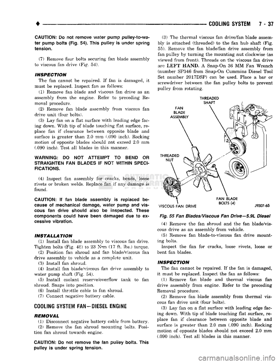
(3) The thermal viscous fan drive/fan blade assem
bly is attached (threaded) to the fan hub shaft (Fig.
55).
Remove the fan blade/fan drive assembly from
fan pulley by turning the mounting nut clockwise (as
viewed from front). Threads on the viscous fan drive are LEFT HAND. A Snap-On 36 MM Fan Wrench
(number SP346 from Snap-On Cummins Diesel Tool
Set number 2017DSP) can be used. Place a bar or
screwdriver between the fan pulley bolts to prevent
pulley from rotating.
THREADED
Fig.
55 Fan
Blades/Viscous
Fan Drive-5.9L
Diesel
(4) Remove the fan shroud and the fan blade/vis
cous drive as an assembly from vehicle.
(5) Remove fan blade-to-viscous fan drive mount
ing bolts.
Inspect the fan for cracks, loose rivets, loose or
bent fan blades.
INSPECTION The fan cannot be repaired. If the fan is damaged,
it must be replaced. Inspect the fan as follows:
(1) Remove fan blade and thermal viscous fan
drive assembly from engine. Refer to the preceding
Removal procedure.
(2) Remove fan blade assembly from thermal vis
cous fan drive unit (four bolts). (3) Lay fan on a flat surface with leading edge fac
ing down. With tip of blade touching flat surface, re
place fan if clearance between opposite blade and surface is greater than 2.0 mm (.090 inch). Rocking
motion of opposite blades should not exceed 2.0 mm (.090 inch). Test all blades in this manner.
Page 309 of 1502
7 - 38
COOLING
SYSTEM
•
WARNING:
DO NOT
ATTEMPT
TO
BEND
OR
STRAIGHTEN
FAN
BLADES
IF
NOT WITHIN
SPECI
FICATIONS.
(4) Inspect fan assembly for cracks, bends, loose
rivets or broken welds. Replace fan if any damage is
found.
CAUTION; If the fan
blade assembly
is
replaced
be
cause
of
mechanical damage,
the fan
pulley
and
viscous
fan
drive should also
be
inspected.
These
components
could have been damaged
due to ex
cessive
vibration.
INSTALLATION
(1) Install fan blade assembly to viscous fan drive.
Tighten mounting bolts.
(2) Position the fan shroud and fan blade/viscous
fan drive to the vehicle as an assembly.
(3) Install viscous fan drive assembly on fan hub
shaft. Tighten mounting nut to 57 N*m (42 ft. lbs.)
torque.
(4) Install fan shroud bolts.
(5) Install battery cable to battery.
VISCOUS
FAN
DRIVE
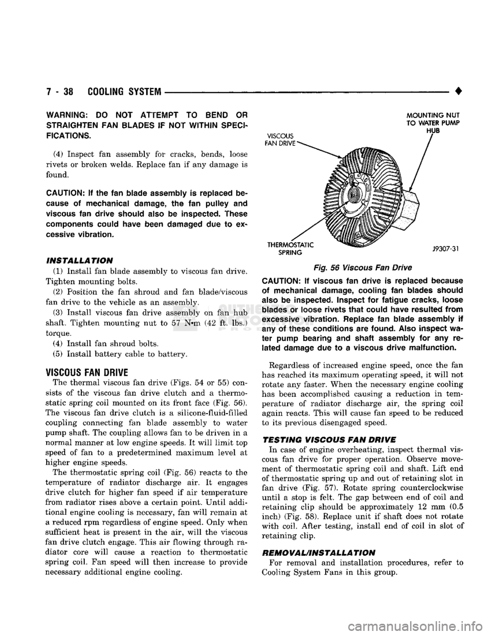
The thermal viscous fan drive (Figs. 54 or 55) con
sists of the viscous fan drive clutch and a thermo
static spring coil mounted on its front face (Fig. 56).
The viscous fan drive clutch is a silicone-fluid-filled coupling connecting fan blade assembly to water
pump shaft. The coupling allows fan to be driven in a normal manner at low engine speeds. It will limit top
speed of fan to a predetermined maximum level at
higher engine speeds.
The thermostatic spring coil (Fig. 56) reacts to the
temperature of radiator discharge air. It engages drive clutch for higher fan speed if air temperature
from radiator rises above a certain point. Until addi
tional engine cooling is necessary, fan will remain at a reduced rpm regardless of engine speed. Only when
sufficient heat is present in the air, will the viscous
fan drive clutch engage. This air flowing through ra diator core will cause a reaction to thermostatic spring coil. Fan speed will then increase to provide
necessary additional engine cooling.
MOUNTING
NUT
TO WATER PUMP
Fig.
56
Viscous
Fan Drive CAUTION; If
viscous
fan
drive
is
replaced because
of mechanical damage, cooling
fan
blades should
also
be
inspected. Inspect
for
fatigue cracks, loose
blades
or
loose rivets
that
could have resulted
from
excessive
vibration. Replace
fan
blade assembly
if
any
of
these conditions
are
found.
Also
inspect
wa
ter
pump bearing
and
shaft assembly
for any re
lated
damage
due to a
viscous
drive malfunction.
Regardless of increased engine speed, once the fan
has reached its maximum operating speed, it will not
rotate any faster. When the necessary engine cooling
has been accomplished causing a reduction in tem perature of radiator discharge air, the spring coil again reacts. This will cause fan speed to be reduced
to its previous disengaged speed.
TESTING VISCOUS FAN DRIVE In case of engine overheating, inspect thermal vis
cous fan drive for proper operation. Observe move
ment of thermostatic spring coil and shaft. Lift end
of thermostatic spring up and out of retaining slot in
fan drive (Fig. 57). Rotate spring counterclockwise until a stop is felt. The gap between end of coil and
retaining clip should be approximately 12 mm (0.5 inch) (Fig. 58). Replace unit if shaft does not rotate
with coil. After testing, install end of coil in slot of retaining clip.
REMOVAUINSTALLA
TION For removal and installation procedures, refer to
Cooling System Fans in this group.
Page 314 of 1502
•
*IF VEHICLE IS NOT EQUIPPED
WITH
POWER
STEERING,
THIS
WILL
BE
AN
IDLER PULLEY.
J9307-26
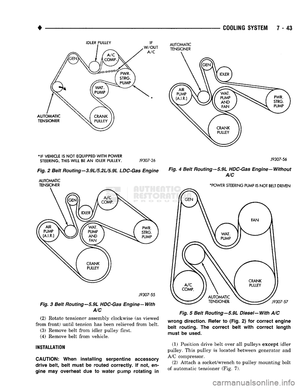
Fig.
2 Beit
Routing
- 3.9U5.2L/5.9L
LDC-Gas
Engine
AUTOMATIC TENSIONER
J9307-55
Fig.
3 Beit Routing—5.9L HDC-Gas Engine—With
A/C
(2)
Rotate tensioner assembly clockwise (as viewed
from front) until tension has been relieved from belt.
(3) Remove belt from idler pulley first.
(4)
Remove belt from vehicle.
INSTALLATION
CAUTION:
When
installing
serpentine accessory
drive
belt, belt
must
be
routed
correctly.
If not, en
gine
may
overheat
due to
water
pump
rotating in
COOLING
SYSTEM
7 - 43
AUTOMATIC TENSIONER
J9307-56
Fig.
4 Belt Routing—5.9L
HDC-Gas
Engine—Without A/C
'POWER STEERING PUMP IS
NOT
BELT DRIVEN
Fig.
5 Belt Routing-5.9L Diesel-With A/C
wrong
direction. Refer
to
(Fig.
2) for
correct engine
belt routing.
The
correct belt with correct length
must
be
used.
(1) Position drive belt over all pulleys except idler
pulley. This pulley is located between generator and
A/C compressor.
(2) Attach a socket/wrench to pulley mounting bolt
of automatic tensioner (Fig. 7).
Page 315 of 1502
7 - 44
COOLING
SYSTEM
•
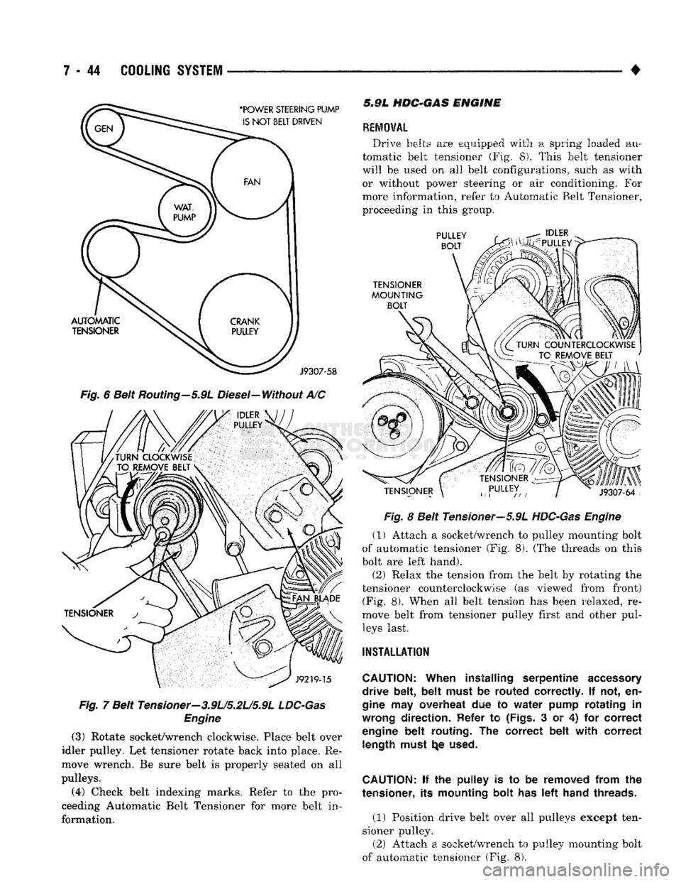
Fig.
6 Belt Routing-5.9L Diesel-Without A/C
Fig.
7 Belt Tensioner-3.9L/5.2U5.9L
LDC-Gas
Engine
(3)
Rotate socket/wrench clockwise. Place belt over
idler pulley. Let tensioner rotate back into place. Re
move wrench. Be sure belt is properly seated on all
pulleys.
(4)
Check belt indexing marks. Refer to the pro
ceeding Automatic Belt Tensioner for more belt in
formation. 5.9L
HDC-GAS
ENGINE
REMOVAL
Drive belts are equipped with a spring loaded au
tomatic belt tensioner (Fig. 8). This belt tensioner
will be used on all belt configurations, such as with or without power steering or air conditioning. For
more information, refer to Automatic Belt Tensioner,
proceeding in this group.
Fig.
8 Belt Tensioner—5.9L
HDC-Gas Engine
(1) Attach a socket/wrench to pulley mounting bolt
of automatic tensioner (Fig. 8). (The threads on this
bolt are left hand).
(2) Relax the tension from the belt by rotating the
tensioner counterclockwise (as viewed from front) (Fig. 8). When all belt tension has been relaxed, re
move belt from tensioner pulley first and other pul leys last.
INSTALLATION
CAUTION:
When installing serpentine
accessory
drive belt, belt must
be
routed correctly.
If not, en
gine
may
overheat
due to
water pump rotating
in
wrong
direction. Refer
to
(Figs.
3 or 4) for
correct
engine
belt routing.
The
correct belt with correct length must
t^e
used.
CAUTION:
if the
pulley
is to be
removed from
the
tensioner,
its
mounting bolt
has left
hand threads.
(1) Position drive belt over all pulleys except ten
sioner pulley. (2) Attach a socket/wrench to pulley mounting bolt
of automatic tensioner (Fig. 8).