1993 DODGE TRUCK clock
[x] Cancel search: clockPage 516 of 1502
WIRING
DIAGRAMS
SW - 41
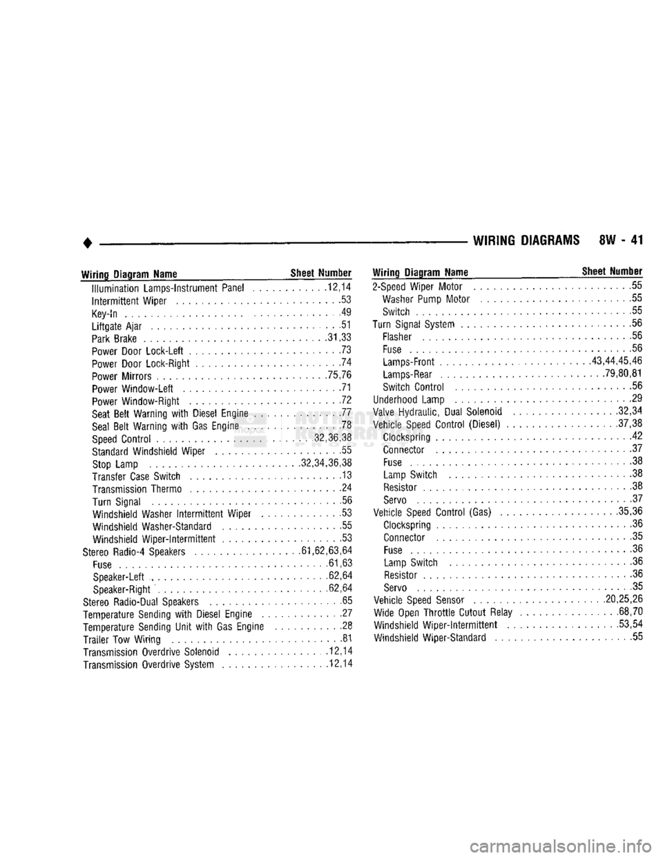
Wiring
Diagram Name _ Sheet Number
Illumination
Lamps-Instrument Panel ........... .12,14
Intermittent
Wiper ......................... .53
Key-In
. . . . . . . .49
Liftgate
Ajar
............................ .51
Park
Brake
.31,33
Power
Door Lock-Left ....................... .73
Power
Door Lock-Right .74
Power
Mirrors .75,76
Power
Window-Left 71
Power
Window-Right . .72
Seat
Belt
Warning
with
Diesel Engine 77
Seal
Belt
Warning
with
Gas Engine .78
Speed
Control
........... ,32,36,38
Standard
Windshield Wiper . .55
Stop
Lamp .32,34,36,38
Transfer
Case
Switch . 13
Transmission
Thermo ....................... .24
Turn Signal .56
Windshield Washer
Intermittent
Wiper . .53
Windshield Washer-Standard .55 Windshield
Wiper-Intermittent
53
Stereo
Radio-4 Speakers .61,62,63,64
Fuse
.61,63
Speaker-Left ......... ............ 62,64
Speaker-Right
. .62,64
Stereo
Radio-Dual Speakers .65
Temperature Sending
with
Diesel Engine . .27
Temperature Sending
Unit
with
Gas Engine .......... .28
Trailer
Tow Wiring 81
Transmission
Overdrive Solenoid ............... .12,14
Transmission
Overdrive System 12,14
Wiring
Diagram Name ^ Sheet Number
2-Speed
Wiper Motor 55
Washer
Pump
Motor
....................... .55
Switch 55
Turn
Signal
System
.......................... .56
Flasher
56
Fuse
.56
Lamps-Front
43,44,45,46
Lamps-Rear
. 79,80,81
Switch
Control
56
Underhood
Lamp 29
Valve
Hydraulic, Dual Solenoid .32,34
Vehicle
Speed
Control
(Diesel) .37,38
Clockspring 42 Connector .37
Fuse
................................. .38
Lamp
Switch . . .38
Resistor
.38
Servo
• .37
Vehicle
Speed
Control
(Gas) .35,36
Clockspring 36
Connector .35
Fuse
......... 36
Lamp
Switch .36
Resistor
.36
Servo
. 35
Vehicle
Speed
Sensor
.20,25,26 Wide Open
Throttle
Cutout Relay . .68,70
Windshield
Wiper-intermittent
...... ....... .53,54
Windshield Wiper-Standard 55
Page 518 of 1502
WIRING
DIAGRAMS
8W - 43
FUSIBLE
LINK
(18GY)
12BK/RD
FUSIBLE
LINK
(200R)
(LEFT
FRONT
WHEELHOUSE) HEATED
REAR
WINDOW
SH
39
FUSIBLE
LINK
(200R)
(LEFT
FRONT
WHEELHOUSE)
I—A22
12BK/0R
IT
1
30
AMPS
J CIRCUIT
,—h BREAKER —P CAVITY
#12
-A22
12BK/0R-
RUN ONLY
IGNITION
SWITCH
SH
10
A31
14BK/WT
RUN
AND ACC
F21
12TN
POWER WINDOW
SH
71
FUSE
#11
30 AMP
CI
12DG
A/C
AND
HEATER BLOWER MOTOR
SH
66.67.69
S
FUSE
#10
10*ZJ20
AMP
O
FUSE
#8
310 AMP
-A41
14YL-
ENGINE
STARTER
SYSTEM
SH
7.8.9
A21
14DB
FUSE
#1
3
2 AMP
RUN
AND
START
V34
20WT/RD
A2I
14DB
VEHICLE
SPEED
CONTROL (GAS)
SH
36
VEHICLE
SPEED
CONTROL (DIESEL)
SH
38
FUSE
#3
20 AMP
F20
18WT
BACK-UP
LAMP
SH
79.80
HEATER REAR WINDOW
SH
39
G5
20DB/WT
TO
4tART
D
FUSE
# 2
3
5 AMP
LAMP LOW
FUSE
#9
120 AMP
V6
18DB
WINDSHIELD WIPER
SYSTEM
SH
54.55
RADIO
AND
CLOCK
SH
61.63.65
L5
18RD
i
TURN SIGNAL FLASHER
SH
56
TACHOMETER
PROVISIONS
SH
48
REAR
WHEEL ANTI-LOCK
MODULE
SH
31.33
AUTOMATIC
SHUT DOWN
RELAY
SH
16.22
TRANSMISSION
OVERDRIVE
SOLENOIDS
SH
12.14
FUEL PUMP RELAY
SH
16
GENERATOR
SH
4
VACUUM SENSOR
SH
34
AIR SWITCHING
SOLENOIDS
SH
16
PMC
SH
16
AIR HEATER CONTROLLER
SH
21
WOT RELAY
SH
68.70
A/C
ELECTRONIC CYCLING SWITCH
SH
68.70
3.R.L.
MODULE
SH
46
EMCC
RELAY
SH
11
FUEL HEATER AND PUMP
SH
24
WAIT
TO
START
SH
57
FUEL LAMP
SH
57
GAUGES
SH
59
BRAKE
LAMP
SH
57.58
SEAT
BELT LAMP AND BUZZER
SH
77 78
WATER
IN
FUEL LAMP
SH
57
4
WHEEL DRIVE
INDICATOR LAMP
SH
13
LOW ENGINE
OIL
LAMP
SH
59
MALFUNCTION
INDICATOR LAMP
SH
59
ANTI-LOCK LAMP
SH
57 58
LIFTGATE OPEN LAMP
SH
58
TRANSMISSION
CONTROL MODULE
SH
12.14
SERVICE
REMINDER INDICATOR LAMP
SH
58
J938W-11
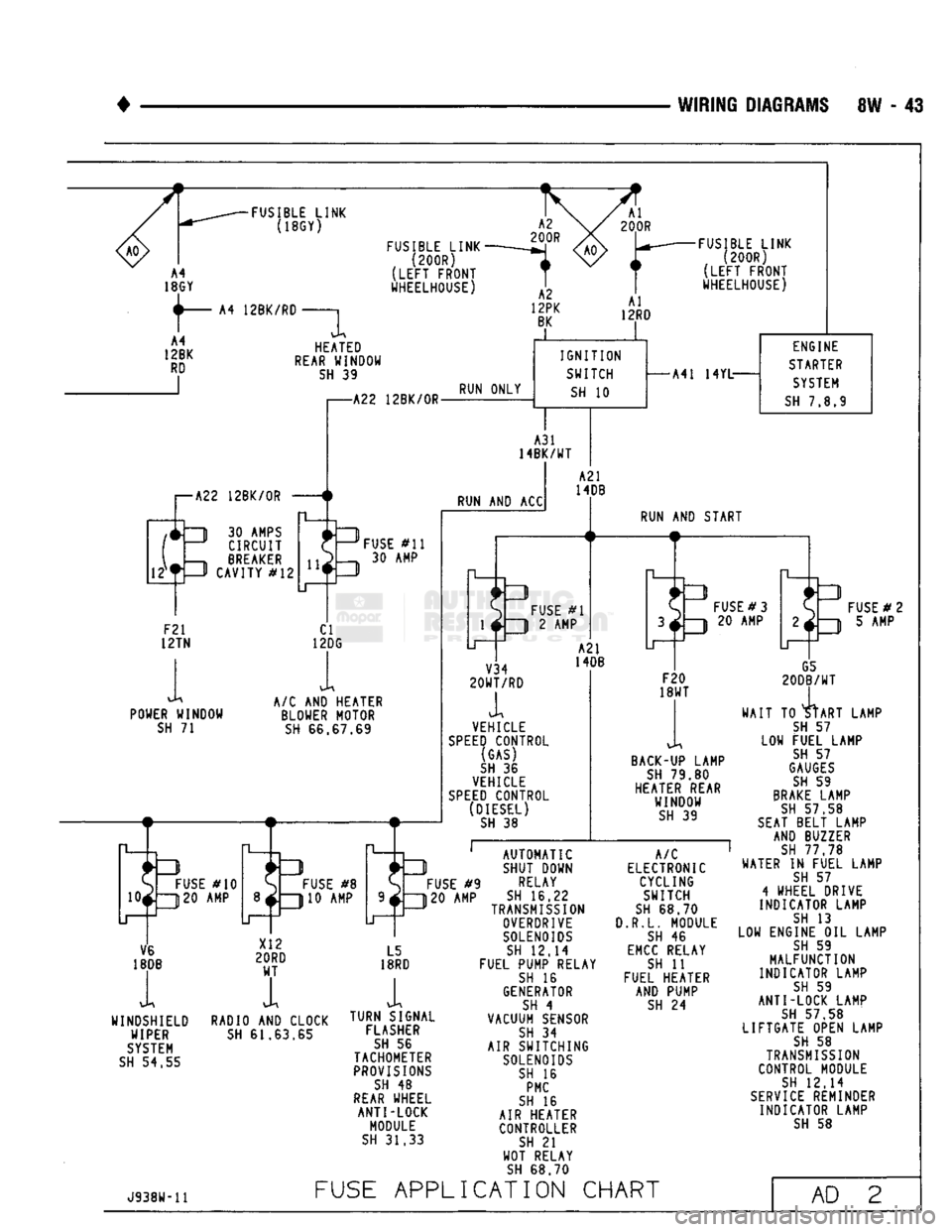
FUSE
APPLICATION
CHART
AD
2
Page 546 of 1502
WIRING DIAGRAMS
8W - 71
TO FUSIBLE
LINK
(SEE
SH 4,6)
:X2
SPLICE
(SEE
SH 47)
FUSE
#4
(20 AMP)
F33
18PK
RD
F33
18PK
RD
HORN RELAY
[ON
FUSE BLOCK)
(SEE
SH 82)
TO HEADLAMP SWITCH
(SEE
SH 47)
LOW NOTE)
HORN
(HIGH
NOTE)
HORN
(LEFT
SIDE
OF RADIATOR SUPPORT) (GAS)
(LEFT
SIDE
SHIELD (DIESEL)
BLACK X2 18DG/RD
(RIGHT
SIDE
OF RADIATOR SUPPORT) (GAS)
(LEFT
SIDE SHIELD
(DIESEL) BLACK
X2
18DG
RD
NOTE:
HORNS
ON
DIESEL
ARE
ON
LEFT SIDE
NEAR BATTERY
32
X2
18DG
RD
X3
20BK/RD
CLOCK SPRING
OR
HORN RING
(IN
COLUMN)
(IN
STEERING COLUMN)
HORN
SWITCH
STEERING
COLUMN
GROUND
(THROUGH CENTER SHAFT)
J938W-11
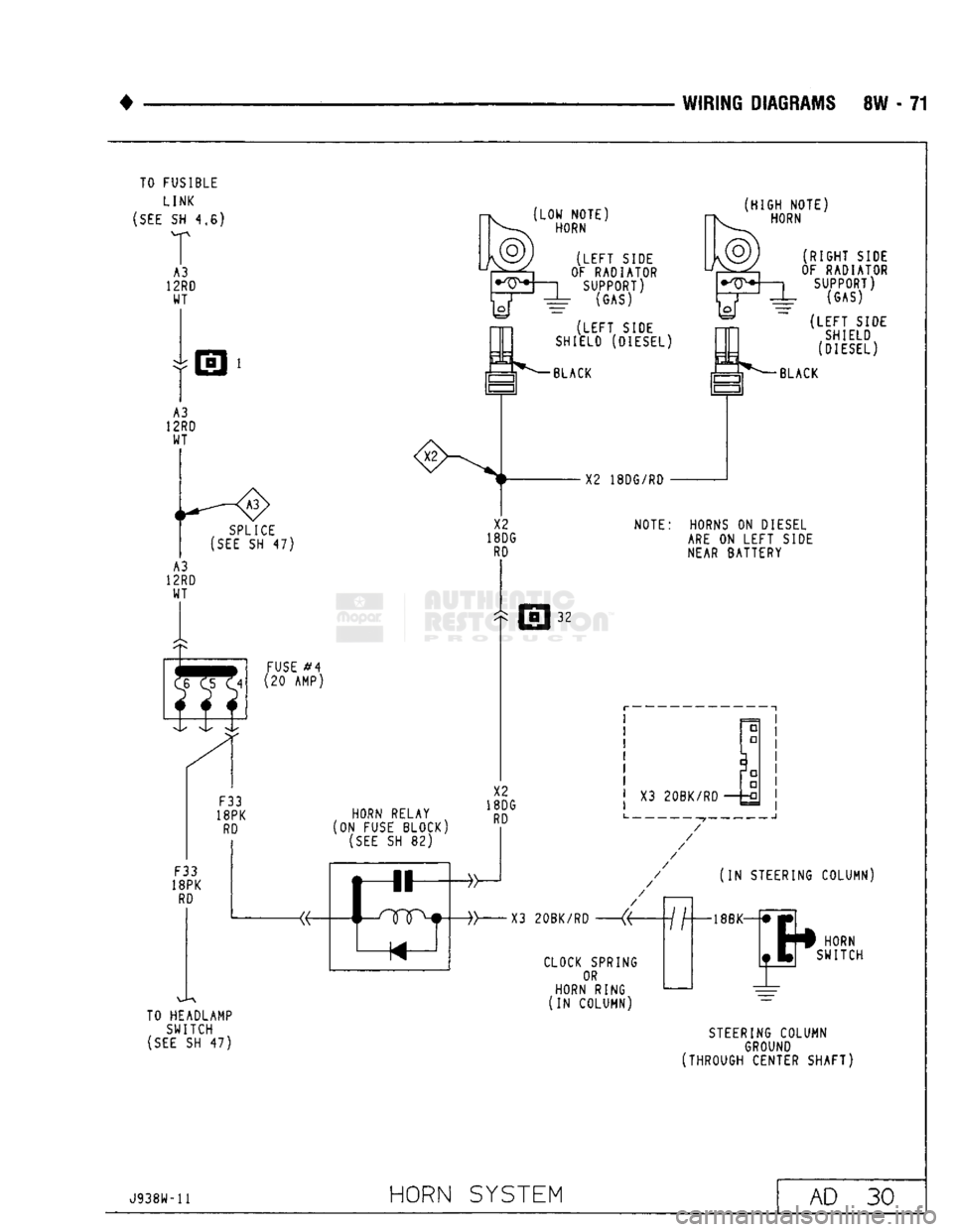
HORN
SYSTEM
AD
30
Page 633 of 1502

9
- 28 3.9L
ENGINE
•
accompanied by excessive clearance between the
valve stem and rocker arm as valve closes. In either
case,
tappet assembly should be removed for inspec
tion and cleaning.
The valve train generates a noise very much like a
light tappet noise during normal operation. Care
must be taken to ensure that tappets are making the
noise. In general, if more than one tappet seems to
be noisy, its probably not the tappets.
REMOVAL
(1) Remove the air cleaner.
(2) Remove cylinder head cover.
(3) Remove rocker assembly and push rods. Iden
tify push rods to ensure installation in original loca
tion.
(4) Remove intake manifold.
(5) Remove yoke retainer and aligning yokes.
(6) Slide Hydraulic Tappet Remover/Installer Tool
C-4129-A
through opening in cylinder head and seat
tool firmly in the head of tappet.
(7) Pull tappet out of bore with a twisting motion.
If all tappets are to be removed, identify tappets to
ensure installation in original location. (8) If the tappet or bore in cylinder block is scored,
scuffed, or shows signs of sticking, ream the bore to
next oversize. Replace with oversize tappet.
CAUTION:
The
plunger
and
tappet bodies
are not
interchangeable.
The
plunger
and
valve must
al
ways
be fitted to the
original body.
It is
advisable
to
work
on one
tappet
at a
time
to
avoid mixing
of
parts.
Mixed parts
are not
compatible.
DO NOT
dis
assemble
a
tappet
on a
dirty
work bench.
DISASSEMBLE (1) Pry out plunger retainer spring clip (Fig. 17).
(2) Clean varnish deposits from inside of tappet
body above plunger cap.
(3) Invert tappet body and remove plunger cap,
plunger, check valve, check valve spring, check valve retainer and plunger spring (Fig. 17). Check valve
could be flat or ball.
ASSEMBLE (1) Clean all tappet parts in a solvent that will re
move all varnish and carbon.
(2) Replace tappets that are unfit for further ser
vice with new assemblies. (3) If plunger shows signs of scoring or wear, in
stall a new tappet assembly. If valve is pitted, or
valve seat on end of plunger is prevented from seat ing, install a new tappet assembly.
(4) Assemble tappets (Fig. 17).
INSTALLATION
(1) Lubricate tappets.
PLUNGER
SPRING CHECK
BALL PLUNGER
RETAINER
SPRING CLIP
ROLLER
TAPPET
BODY RETAINER
I
PLUNGER
CHECK VALVE
SPRING PLUNGER
CAP
J9109-220
Fig.
17 Hydraulic
Tappet
Assembly
(2) Install tappets and push rods in their original
positions. Ensure that the oil feed hole in the side of
the tappet body faces up (away from the crankshaft).
(3) Install aligning yokes with ARROW toward
camshaft.
(4) Install yoke retainer. Tighten the bolts to 23
N*m (200 in. lbs.) torque. Install intake manifold.
(5) Install push rods in original positions. (6) Install rocker arms.
(7) Install cylinder head cover.
(8) Start and operate engine. Warm up to normal
operating temperature.
CAUTION:
To
prevent damage
to
valve mechanism,
engine must
not be run
above fast idle
until
all hy
draulic tappets have
filled
with
oil and
have become
quiet.
VALVE
TIMING
(1) Turn crankshaft until the No.6 exhaust valve
is closing and No.6 intake valve is opening. (2) Insert a 6.350 mm (1/4 inch) spacer between
rocker arm pad and stem tip of No.l intake valve.
Allow spring load to bleed tappet down giving in ef fect a solid tappet. (3) Install a dial indicator so plunger contacts
valve spring retainer as nearly perpendicular as pos sible. Zero the indicator. (4) Rotate the crankshaft clockwise (normal run
ning direction) until the valve has lifted 0.254 mm (0.010 inch). The timing of the crankshaft should
now read from 10° before top dead center to 2° after
top dead center. Remove spacer.
CAUTION:
DO NOT
turn
crankshaft
any
further
clockwise
as
valve spring might bottom
and
result in serious damage.
(5) If reading is not within specified limits: (a) Check sprocket index marks.
(b) Inspect timing chain for wear. (c) Check accuracy of DC mark on timing indica
tor.
Page 642 of 1502
(5) Be sure the connecting rod and connecting rod
cap are identified with the cylinder number. Remove
connecting rod cap. Install connecting rod bolt guide
set on connecting rod bolts.
(6) Pistons and connecting rods must be removed
from top of cylinder block. When removing piston and connecting rod assemblies from the engine, ro
tate crankshaft so that the connecting rod is centered in cylinder bore and at BDC. Be careful not to nick
crankshaft journals.
(7) After removal, install bearing cap on the mat
ing rod.
INSPECTION
Check the crankshaft connecting rod journal for ex
cessive wear, taper and scoring. Check the cylinder block bore for out-of-round,
taper, scoring and scuffing.
Check the pistons for taper and elliptical shape be
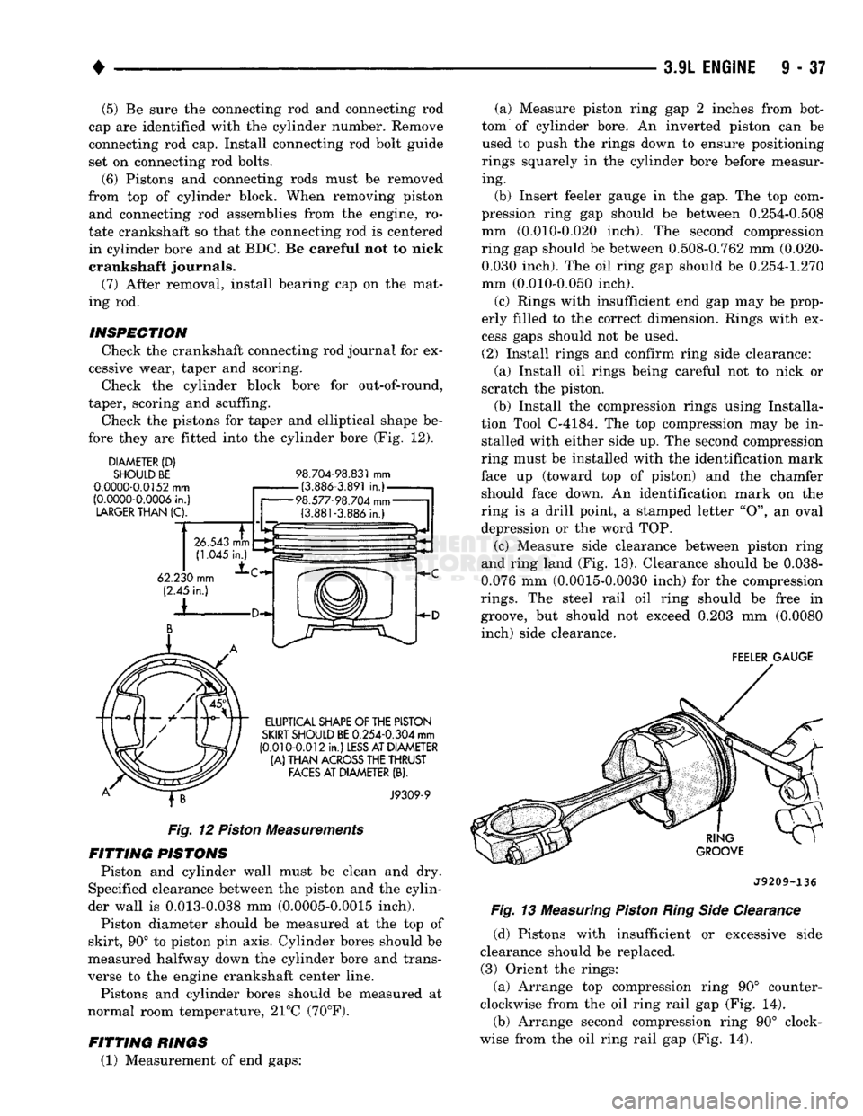
fore they are fitted into the cylinder bore (Fig. 12).
DIAMETER
(D)
SHOULD BE
0.0000-0.0152
mm
(0.0000-0.0006
in.)
LARGER
THAN
(C).
98.704-98.831
mm
-(3.886-3.891
in.)-
98.577-98.704
mm-
(3.881-3.886
in.) (a) Measure piston ring gap 2 inches from bot
tom of cylinder bore. An inverted piston can be used to push the rings down to ensure positioning
rings squarely in the cylinder bore before measur ing.
(b) Insert feeler gauge in the gap. The top com
pression ring gap should be between 0.254-0.508
mm (0.010-0.020 inch). The second compression
ring gap should be between 0.508-0.762 mm (0.020- 0.030 inch). The oil ring gap should be 0.254-1.270
mm (0.010-0.050 inch).
(c) Rings with insufficient end gap may be prop
erly filled to the correct dimension. Rings with ex
cess gaps should not be used.
(2) Install rings and confirm ring side clearance: (a) Install oil rings being careful not to nick or
scratch the piston.
(b) Install the compression rings using Installa
tion Tool C-4184. The top compression may be in stalled with either side up. The second compression
ring must be installed with the identification mark
face up (toward top of piston) and the chamfer should face down. An identification mark on the
ring is a drill point, a stamped letter "O", an oval
depression or the word TOP.
(c) Measure side clearance between piston ring
and ring land (Fig. 13). Clearance should be 0.038-
0.076 mm (0.0015-0.0030 inch) for the compression
rings.
The steel rail oil ring should be free in groove, but should not exceed 0.203 mm (0.0080 inch) side clearance.
FEELER
GAUGE
ELLIPTICAL SHAPE
OF
THE PISTON
SKIRT
SHOULD
BE
0.254-0.304
mm
(0.010-0.012
in.)
LESS
AT DIAMETER
(A)
THAN
ACROSS
THE THRUST
FACES
AT DIAMETER
(B).
J9309-9
Fig.
12
Piston
Measurements
FITTING
PISTONS
Piston and cylinder wall must be clean and dry.
Specified clearance between the piston and the cylin
der wall is 0.013-0.038 mm (0.0005-0.0015 inch). Piston diameter should be measured at the top of
skirt, 90° to piston pin axis. Cylinder bores should be
measured halfway down the cylinder bore and trans
verse to the engine crankshaft center line.
Pistons and cylinder bores should be measured at
normal room temperature, 21°C (70°F).
FITTING
RINGS
(1) Measurement of end gaps: J9209-136
Fig.
13
Measuring
Piston
Ring Side
Clearance (d) Pistons with insufficient or excessive side
clearance should be replaced. (3) Orient the rings:
(a) Arrange top compression ring 90° counter
clockwise from the oil ring rail gap (Fig. 14). (b) Arrange second compression ring 90° clock
wise from the oil ring rail gap (Fig. 14).
Page 645 of 1502
S
- 40 3.9L
ENGINE
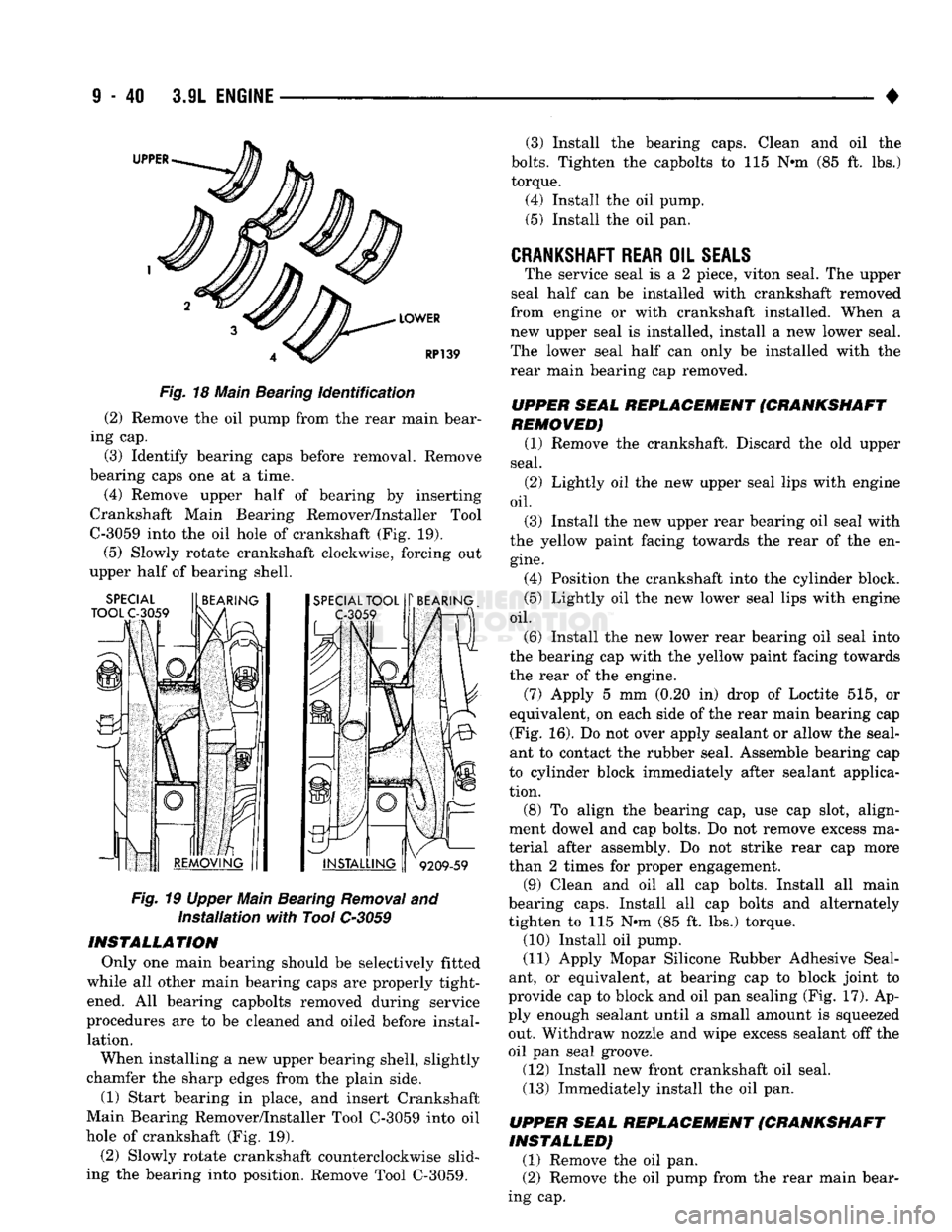
39 Fig.
18 Main Bearing identification
(2) Remove the oil pump from the rear main bear
ing cap.
(3) Identify bearing caps before removal. Remove
bearing caps one at a time.
(4) Remove upper half of bearing by inserting
Crankshaft Main Bearing Remover/Installer Tool
C-3059 into the oil hole of crankshaft (Fig. 19).
(5)
Slowly rotate crankshaft clockwise, forcing out
upper half of bearing shell.
Fig.
19 Upper Main Bearing Removal and installation with Tool
C-3059
INSTALLATION Only one main bearing should be selectively fitted
while all other main bearing caps are properly tight ened. All bearing capbolts removed during service
procedures are to be cleaned and oiled before instal lation.
When installing a new upper bearing shell, slightly
chamfer the sharp edges from the plain side.
(1) Start bearing in place, and insert Crankshaft
Main Bearing Remover/Installer Tool C-3059 into oil
hole of crankshaft (Fig. 19).
(2) Slowly rotate crankshaft counterclockwise slid
ing the bearing into position. Remove Tool C-3059. (3) Install the bearing caps. Clean and oil the
bolts.
Tighten the capbolts to 115 N*m (85 ft. lbs.)
torque.
(4) Install the oil pump. (5) Install the oil pan.
CRANKSHAFT REAR
OIL
SEALS
The service seal is a 2 piece, viton seal. The upper
seal half can be installed with crankshaft removed
from engine or with crankshaft installed. When a
new upper seal is installed, install a new lower seal.
The lower seal half can only be installed with the
rear main bearing cap removed.
UPPER SEAL REPLACEMENT (CRANKSHAFT
REMOVED)
(1) Remove the crankshaft. Discard the old upper
seal.
(2) Lightly oil the new upper seal lips with engine
oil.
(3) Install the new upper rear bearing oil seal with
the yellow paint facing towards the rear of the en
gine.
(4) Position the crankshaft into the cylinder block.
(5) Lightly oil the new lower seal lips with engine
oil.
(6) Install the new lower rear bearing oil seal into
the bearing cap with the yellow paint facing towards the rear of the engine.
(7) Apply 5 mm (0.20 in) drop of Loctite 515, or
equivalent, on each side of the rear main bearing cap (Fig. 16). Do not over apply sealant or allow the seal
ant to contact the rubber seal. Assemble bearing cap
to cylinder block immediately after sealant applica
tion.
(8) To align the bearing cap, use cap slot, align
ment dowel and cap bolts. Do not remove excess ma
terial after assembly. Do not strike rear cap more
than 2 times for proper engagement. (9) Clean and oil all cap bolts. Install all main
bearing caps. Install all cap bolts and alternately
tighten to 115 N*m (85 ft. lbs.) torque. (10) Install oil pump.
(11) Apply Mopar Silicone Rubber Adhesive Seal
ant, or equivalent, at bearing cap to block joint to
provide cap to block and oil pan sealing (Fig. 17). Ap
ply enough sealant until a small amount is squeezed out. Withdraw nozzle and wipe excess sealant off the
oil pan seal groove. (12) Install new front crankshaft oil seal.
(13) Immediately install the oil pan.
UPPER SEAL REPLACEMENT (CRANKSHAFT
INSTALLED)
(1) Remove the oil pan. (2) Remove the oil pump from the rear main bear
ing cap.
Page 663 of 1502
CAUTION:
Th© plunger and
tappet
bodies are not
interchangeable. The plunger and valve must al
ways
be
fitted
to the
original
body. It is advisable to
work
on one
tappet
at a
time
to avoid
mixing
of parts. Mixed
parts
are not
compatible.
DO NOT
dis
assemble
a
tappet
on a
dirty
work
bench,
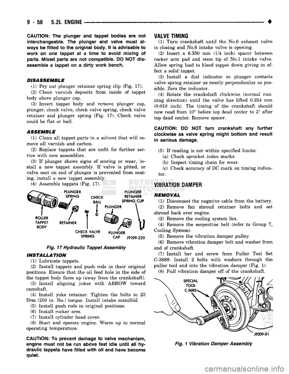
DISASSEMBLE
(1) Pry out plunger retainer spring clip (Fig. 17).
(2) Clean varnish deposits from inside of tappet
body above plunger cap.
(3) Invert tappet body and remove plunger cap,
plunger, check valve, check valve spring, check valve
retainer and plunger spring (Fig. 17). Check valve could be flat or ball.
ASSEMBLE
(1) Clean all tappet parts in a solvent that will re
move all varnish and carbon.
(2) Replace tappets that are unfit for further ser
vice with new assemblies.
(3) If plunger shows signs of scoring or wear, in
stall a new tappet assembly. If valve is pitted, or
valve seat on end of plunger is prevented from seat
ing, install a new tappet assembly. (4) Assemble tappets (Fig. 17).
PLUNGER
CHECK
BALL
PLUNGER
RETAINER
SPRING CLIP
ROLLER
TAPPET BODY RETAINER I PLUNGER
CHECK VALVE
SPRING PLUNGER
CAP
J9109-220
Fig.
17 Hydraulic
Tappet
Assembly
INSTALLATION
(1) Lubricate tappets.
(2) Install tappets and push rods in their original
positions. Ensure that the oil feed hole in the side of
the tappet body faces up (away from the crankshaft). (3) Install aligning yokes with ARROW toward
camshaft. (4) Install yoke retainer. Tighten the bolts to 23
N»m (200 in. lbs.) torque. Install intake manifold. (5) Install push rods in original positions.
(6) Install rocker arm.
(7) Install cylinder head cover.
(8) Start and operate engine. Warm up to normal
operating temperature.
CAUTION: To
prevent
damage to valve mechanism,
engine must not be run above
fast
idle
until
all hy
draulic
tappets
have
filled
with
oil and have become
quiet.
VALVE
TIMING
(1) Turn crankshaft until the No.6 exhaust valve
is closing and No.6 intake valve is opening. (2) Insert a 6.350 mm (1/4 inch) spacer between
rocker arm pad and stem tip of No.l intake valve. Allow spring load to bleed tappet down giving in ef
fect a solid tappet. (3) Install a dial indicator so plunger contacts
valve spring retainer as nearly perpendicular as pos
sible.
Zero the indicator. (4) Rotate the crankshaft clockwise (normal run
ning direction) until the valve has lifted 0.254 mm (0.010 inch). The timing of the crankshaft should
now read from 10° before top dead center to 2° after
top dead center. Remove spacer.
CAUTION:
DO NOT
turn
crankshaft any
further
clockwise as valve spring
might
bottom
and
result
in serious
damage.
(5) If reading is not within specified limits: (a) Check sprocket index marks.
(b) Inspect timing chain for wear.
(c) Check accuracy of DC mark on timing indica
tor.
VIBRATION DAMPER
REMOVAL (1) Disconnect the negative cable from the battery.
(2) Remove fan shroud retainer bolts and set
shroud back over engine.
(3) Remove the cooling system fan.
(4) Remove the serpentine belt (refer to Group 7,
Cooling System).
(5) Remove the vibration damper pulley. (6) Remove vibration damper bolt and washer from
end of crankshaft. (7) Install bar and screw from Puller Tool Set
C-3688. Install 2 bolts with washers through the
puller tool and into the vibration damper (Fig. 1).
(8) Pull vibration damper off of the crankshaft.
J9209-81
Fig.
1
Vibration
Damper
Assembly
Page 674 of 1502
5.2L ENGINE
9 - 69
BEARING
CAP
J9309-72
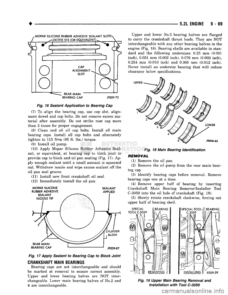
Fig.
16 Sealant Application to Bearing Cap (7) To align the bearing cap, use cap slot, align
ment dowel and cap bolts. Do not remove excess ma
terial after assembly. Do not strike rear cap more
than 2 times for proper engagement.
(8) Clean and oil all cap bolts. Install all main
bearing caps. Install all cap bolts and alternately
tighten to 115 Nnn (85 ft. lbs.) torque.
(9) Install oil pump.
(10) Apply Mopar Silicone Rubber Adhesive Seal
ant, or equivalent, at bearing cap to block joint to
provide cap to block and oil pan sealing (Fig. 17). Ap
ply enough sealant until a small amount is squeezed out. Withdraw nozzle and wipe excess sealant off the
oil pan seal groove.
(11) Install new front crankshaft oil seal.
(12) Immediately install the oil pan.
MOPAR SILICONE SEALANT
RUBBER
ADHESIVE APPLIED
Fig.
17
Apply
Sealant to Bearing Cap to
Block
Joint
CRANKSHAFT
MAIN BEARINGS
Bearing caps are not interchangeable and should
be marked at removal to ensure correct assembly.
Upper and lower bearing halves are NOT inter changeable. Lower main bearing halves of No.2 and
4
are interchangeable. Upper and lower No.3 bearing halves are flanged
to carry the crankshaft thrust loads. They are NOT interchangeable with any other bearing halves in the
engine (Fig. 18). Bearing shells are available in stan
dard and the following under
sizes:
0.25 mm (0.001
inch),
0.051 mm (0.002 inch), 0.076 mm (0.003 inch),
0.254 mm (0.010 inch) and 0.305 mm (0.012 inch).
Never install an undersize bearing that will reduce
clearance below specifications.
Fig.
18 Main Bearing
Identification
REMOVAL (1) Remove the oil pan.
(2) Remove the oil pump from the rear main bear
ing cap.
(3) Identify bearing caps before removal. Remove
bearing caps one at a time.
(4) Remove upper half of bearing by inserting
Crankshaft Main Bearing Remover/Installer Tool
C-3059 into the oil hole of crankshaft (Fig. 19).
(5) Slowly rotate crankshaft clockwise, forcing out
upper half of bearing shell.
Fig.
19 Upper Main Bearing
Removal
and
Installation
with
Tool C-3059