1993 DODGE TRUCK clock
[x] Cancel search: clockPage 729 of 1502
9
- 124 5.9L
(DIESEL)
ENGINE
Fig.
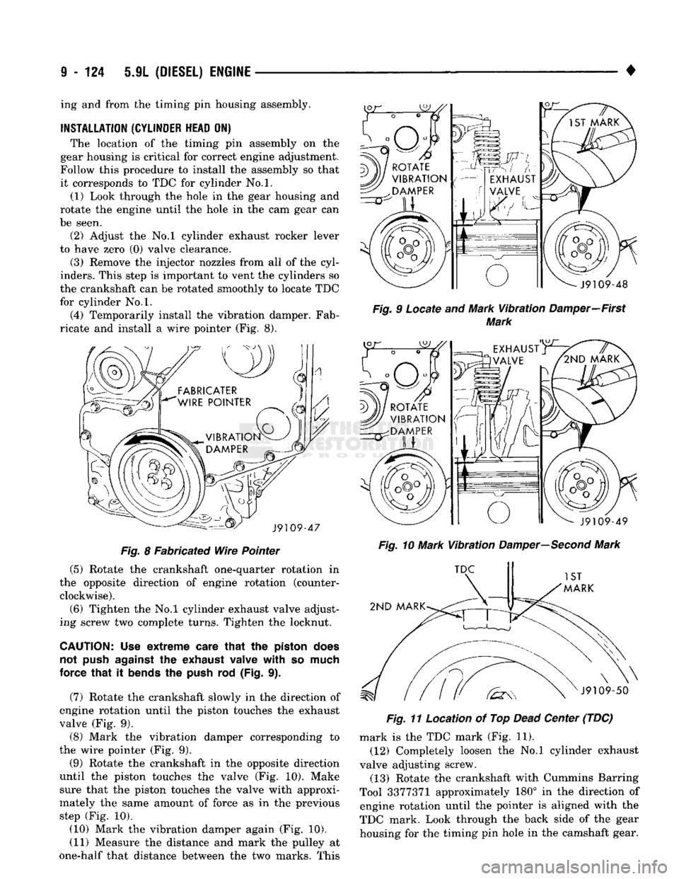
8 Fabricated Wire Pointer (5) Rotate the crankshaft one-quarter rotation in
the opposite direction of engine rotation (counter clockwise).
(6) Tighten the No.l cylinder exhaust valve adjust
ing screw two complete turns. Tighten the locknut.
CAUTION; Use extreme
care
that
the
piston
does
not
push
against
the
exhaust
valve with so
much
force that it
bends
the
push
rod (Fig. 9).
(7) Rotate the crankshaft slowly in the direction of
engine rotation until the piston touches the exhaust
valve (Fig. 9). (8) Mark the vibration damper corresponding to
the wire pointer (Fig. 9).
(9) Rotate the crankshaft in the opposite direction
until the piston touches the valve (Fig. 10). Make sure that the piston touches the valve with approxi
mately the same amount of force as in the previous step (Fig. 10).
(10) Mark the vibration damper again (Fig. 10). (11) Measure the distance and mark the pulley at
one-half that distance between the two marks. This •
Fig.
9 Locate and Mark
Vibration
Damper—First
Mark
Fig.
10 Mark
Vibration
Damper—Second
Mark
Fig.
11 Location of Top
Dead
Center (TDC) mark is the TDC mark (Fig. 11).
(12) Completely loosen the No.l cylinder exhaust
valve adjusting screw. (13) Rotate the crankshaft with Cummins Barring
Tool 3377371 approximately 180° in the direction of engine rotation until the pointer is aligned with the
TDC mark. Look through the back side of the gear housing for the timing pin hole in the camshaft gear.
ing and from the timing pin housing assembly.
INSTALLATION
(CYLINDER
HEAD
ON) The location of the timing pin assembly on the
gear housing is critical for correct engine adjustment.
Follow this procedure to install the assembly so that it corresponds to TDC for cylinder No.l. (1) Look through the hole in the gear housing and
rotate the engine until the hole in the cam gear can
be seen. (2) Adjust the No.l cylinder exhaust rocker lever
to have zero (0) valve clearance.
(3) Remove the injector nozzles from all of the cyl
inders. This step is important to vent the cylinders so
the crankshaft can be rotated smoothly to locate TDC
for cylinder No.l.
(4) Temporarily install the vibration damper. Fab
ricate and install a wire pointer (Fig. 8).
Page 744 of 1502
•
5.9L
(DIESEL) ENGINE 9 - 139
Fig.
2 Main Beating Cap
Removal
CAUTION:
Crankshaft must be
lifted
straight
off the
bearings
to
prevent
damage
to the
thrust
bearings.
Fig.
3 Lifting Crankshaft out of Cylinder
Block
(7)
Remove the main bearings from the block and
the main caps. (8) Remove the piston cooling nozzles by using a
3/16 inch pin punch to push them out (Fig. 4).
Fig.
4
Piston
Cooling
Nozzles
CLEANING
AND
INSPECTION
Clean the crankshaft oil galley holes with a nylon
brush. Rinse in clean solvent and dry with compressed air. Inspect the front and rear seal contact areas of the
crankshaft for scratches or grooving. The service seal kit will position the seal slightly
deeper into the seal bore so it will contact the crank
shaft at a different location. If this has already been
done and the crankshaft has two worn areas, install
a wear sleeve to provide a new contact surface for
the seal.
Inspect the rod and main journal for deep scores,
signs of overheating and other abnormal marks.
CRANKSHAFT
REWORK
Crankshaft main and rod journals may be ground
in increments of 0.25 mm (0.0098 inch) up to a total
of 1.00 mm (0.0394 inch). The only exception is the main journal thrust
width surface. This journal must be ground in incre ments of 0.50 mm (0.0197 inch) up to a total of 1.00
mm (0.0394 inch). The thrust surface is located on
the No.6 main bearing. When the thrust surface re quires grinding, the main journal must be ground to
the same undersize dimension.
MAIN
JOURNAL
All main journals are to be ground in the opposite
direction of engine rotation (clockwise as viewed
from the front of crankshaft). Polish the journals in
the same direction as engine rotation.
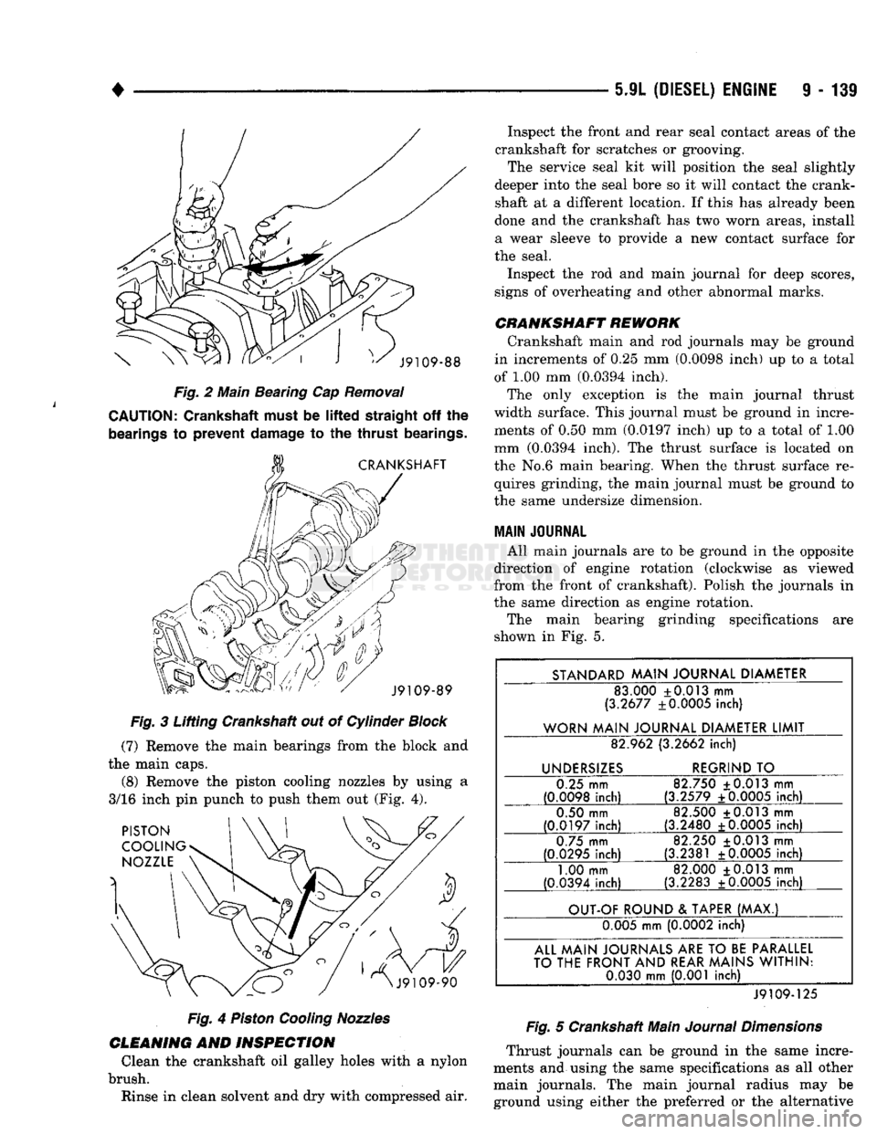
The main bearing grinding specifications are
shown in Fig. 5.
STANDARD
MAIN
JOURNAL
DIAMETER
83.000 +0.013 mm
(3.2677 ±0.0005 inch)
WORN
MAIN
JOURNAL
DIAMETER
LIMIT
82.962 (3.2662
inch)
UNDERSIZES
REGRIND
TO
0.25 mm
(0.0098
inch)
82.750 ±0.013 mm
(3.2579 ±0.0005
inch)
0.50 mm
(0.0197
inch)
82.500 +0.013 mm
(3.2480 +0.0005
inch)
0.75 mm
(0.0295
inch)
82.250 +0.013 mm
(3.2381 ±0.0005
inch)
1.00 mm
(0.0394 inch) 82.000 +0.013 mm
(3.2283 ±0.0005 inch)
OUT-OF
ROUND
&
TAPER
(MAX.)
0.005 mm (0.0002 inch)
ALL
MAIN
JOURNALS
ARE
TO
BE
PARALLEL
TO
THE
FRONT
AND
REAR
MAINS
WITHIN:
0.030
mm
(0.001 inch)
J9109-125
Fig.
5 Crankshaft Main
Journal
Dimensions
Thrust journals can be ground in the same incre
ments and using the same specifications as all other main journals. The main journal radius may be ground using either the preferred or the alternative
Page 745 of 1502
9
- 140 5.9L
(DIESEL)
ENGINE
• procedure providing
the
thrust surface width
is not
being ground.
The
preferred procedure must
be
used
when
the
main bearing thrust width surface
is
ground. When
the
thrust surface width requires
grinding,
the
main journal must
be
ground
to the
same undersize dimension
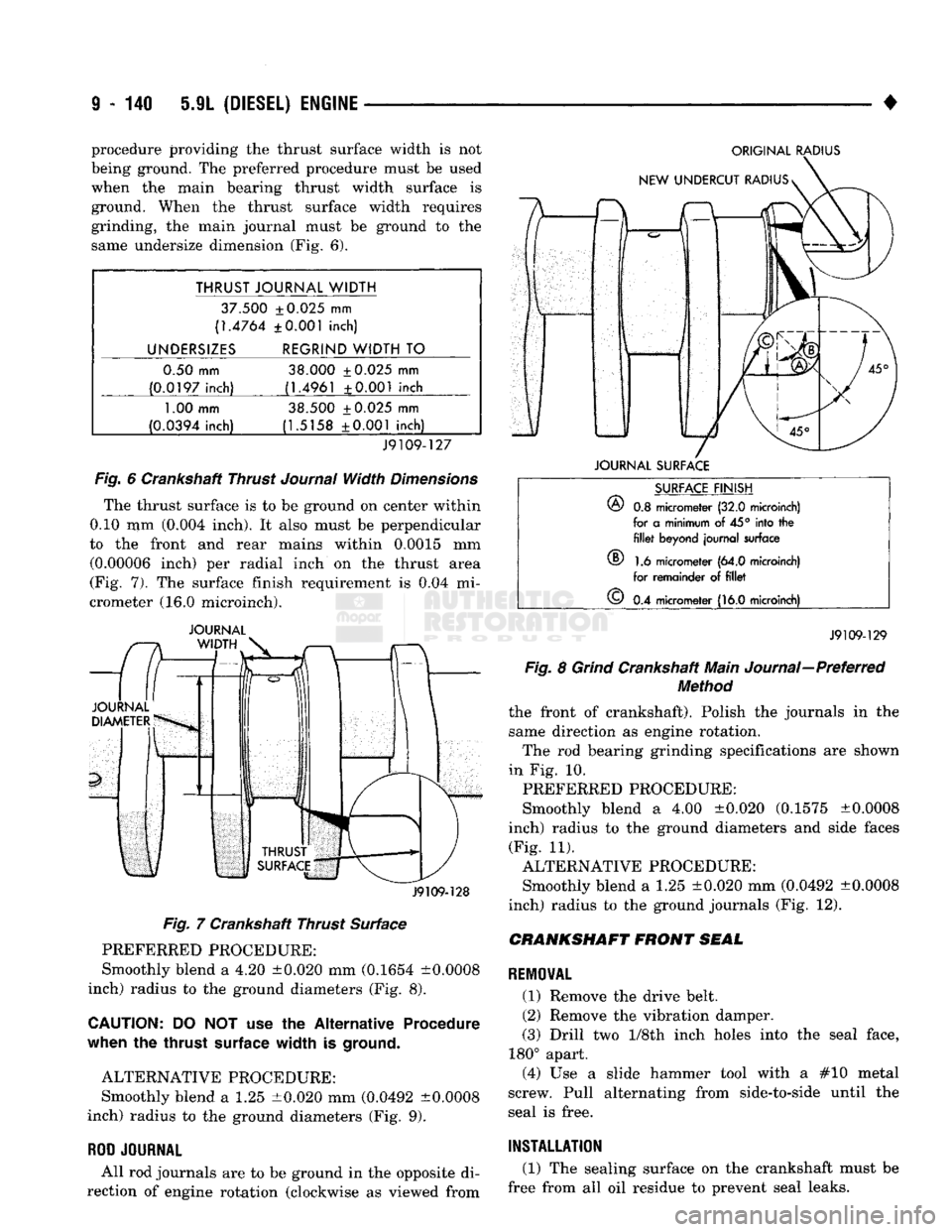
(Fig. 6).
THRUST JOURNAL WIDTH
37.500 ±0.025
mm
(1.4764 ±0.001 inch)
UNDERSIZES REGRIND WIDTH
TO
0.50 mm 38.000 ±0.025
mm
(0.0197 inch) (1.4961 ±0.001 inch
1.00
mm 38.500 ±0.025
mm
(0.0394 inch) (1.5158 ±0.001 inch)
J9109-127
Fig.
6
Crankshaft Thrust
Journal
Width
Dimensions
The thrust surface
is to be
ground
on
center within
0.10
mm
(0.004 inch).
It
also must
be
perpendicular
to
the
front
and
rear mains within 0.0015
mm
(0.00006 inch)
per
radial inch
on the
thrust area
(Fig.
7). The
surface finish requirement
is 0.04 mi
crometer
(16.0
microinch).
JOURNAL
J9109-128
Fig.
7
Crankshaft Thrust Surface PREFERRED PROCEDURE:
Smoothly blend
a 4.20
±0.020
mm
(0.1654 ±0.0008
inch) radius
to the
ground diameters
(Fig. 8).
CAUTION:
DO NOT use the
Alternative Procedure
when
the
thrust
surface
width
is
ground.
ALTERNATIVE PROCEDURE: Smoothly blend
a 1.25
±0.020
mm
(0.0492 ±0.0008
inch) radius
to the
ground diameters
(Fig. 9).
ROD
JOURNAL
All
rod
journals
are to be
ground
in the
opposite
di
rection
of
engine rotation (clockwise
as
viewed from
ORIGINAL
RADIUS
JOURNAL
SURFACE
®
SURFACE
FINISH
®
0.8
micrometer
(32.0
microinch)
for
a
minimum
of 45°
into
the fillet
beyond journal surface
1.6
micrometer
(64.0
microinch)
for remainder
of fillet
©
0.4
micrometer
(16.0
microinch)
J9109-129
Fig.
8
Grind
Crankshaft Main Journal—Preferred
Method
the front
of
crankshaft). Polish
the
journals
in the
same direction
as
engine rotation. The
rod
bearing grinding specifications
are
shown
in
Fig. 10.
PREFERRED PROCEDURE:
Smoothly blend
a 4.00
±0.020 (0.1575 ±0.0008
inch) radius
to the
ground diameters
and
side faces (Fig.
11).
ALTERNATIVE PROCEDURE: Smoothly blend
a 1.25
±0.020
mm
(0.0492 ±0.0008
inch) radius
to the
ground journals
(Fig. 12).
CRANKSHAFT
FRONT
SEAL
REMOVAL
(1) Remove
the
drive belt.
(2) Remove
the
vibration damper.
(3) Drill
two 1/Sth
inch holes into
the
seal face,
180° apart. (4)
Use a
slide hammer tool with
a #10
metal
screw. Pull alternating from side-to-side until
the
seal
is
free.
INSTALLATION
(1)
The
sealing surface
on the
crankshaft must
be
free from
all oil
residue
to
prevent seal leaks.
Page 747 of 1502
9
- 142 5.9L
(DIESEL)
ENGINE
•
ORIGINAL
RADIUS
SURFACE
FINISH
®
0.3
micrometer
(32.0
microinch)
for a
minimum
of
45° into the
^ fillet
beyond
journal
surface
v§/
1.6
micrometer
(64.0
microinch)
^ for
remainder
of
fillet
v£)
0.4
micrometer
(16.0
microinch)
WIDTH OF REGRIND/UNDERCUT RADIUS
©
34.79
±
0.025
mm
(1.369
±0.001 in)
J9109-132
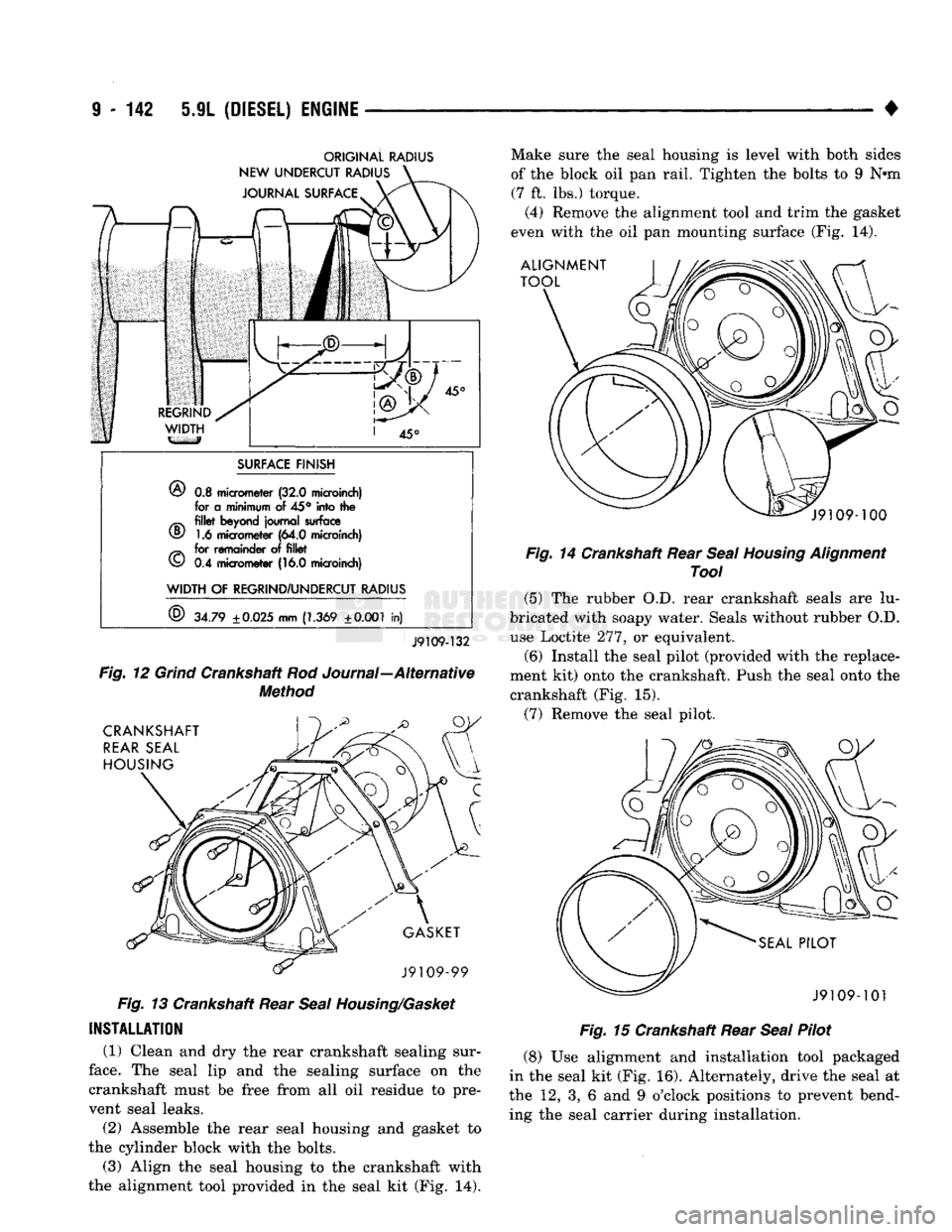
Fig.
12
Grind
Crankshaft Rod Journal—Alternative
Method
Fig.
13 Crankshaft Rear
Seal
Housing/Gasket
INSTALLATION
(1) Clean and dry the rear crankshaft sealing sur
face.
The seal lip and the sealing surface on the
crankshaft must be free from all oil residue to pre vent seal leaks.
(2) Assemble the rear seal housing and gasket to
the cylinder block with the bolts.
(3) Align the seal housing to the crankshaft with
the alignment tool provided in the seal kit (Fig. 14). Make sure the seal housing is level with both sides
of the block oil pan rail. Tighten the bolts to 9 N*m
(7 ft. lbs.) torque.
(4) Remove the alignment tool and trim the gasket
even with the oil pan mounting surface (Fig. 14).
Fig.
14 Crankshaft Rear
Seal
Housing
Alignment
Tool
(5) The rubber O.D. rear crankshaft seals are lu
bricated with soapy water. Seals without rubber O.D. use Loctite 277, or equivalent.
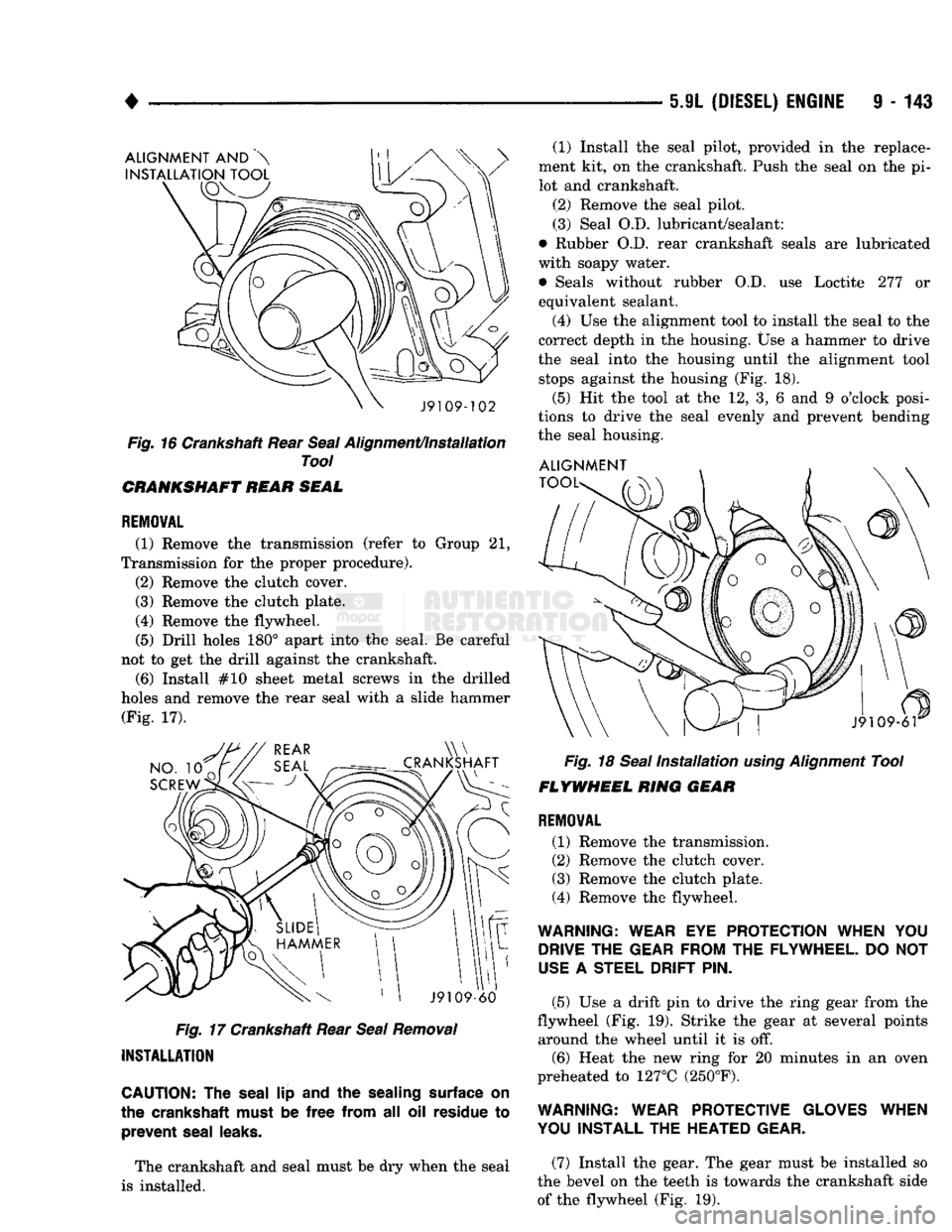
(6) Install the seal pilot (provided with the replace
ment kit) onto the crankshaft. Push the seal onto the
crankshaft (Fig. 15).
(7) Remove the seal pilot.
Fig.
15 Crankshaft Rear
Seal
Pilot
(8) Use alignment and installation tool packaged
in the seal kit (Fig. 16). Alternately, drive the seal at
the 12, 3, 6 and 9 o'clock positions to prevent bend ing the seal carrier during installation.
Page 748 of 1502
•
5.9L
(DIESEL)
ENGINE
9 - 143
ALIGNMENT
AND
INSTALLATION TOOL
J9109-102
Fig.
16 Crankshaft Rear
Seal
Alignment/Installation
Tool
CRANKSHAFT REAR SEAL
REMOVAL
(1) Remove
the
transmission (refer
to
Group
21,
Transmission
for the
proper procedure). (2) Remove
the
clutch cover.
(3) Remove
the
clutch plate. (4) Remove
the
flywheel.
(5) Drill holes
180°
apart into
the
seal.
Be
careful
not
to get the
drill against
the
crankshaft. (6) Install
#10
sheet metal screws
in the
drilled
holes
and
remove
the
rear seal with
a
slide hammer (Fig.
17).
NO.
10
SCREW
\W
CRANKSHAFT
J9109-60
Fig.
17 Crankshaft Rear
Seal
Removal
INSTALLATION
CAUTION:
The
seal
lip
and
the
sealing surface
on
the crankshaft must
be
free
from
all oil
residue
to
prevent
seal leaks.
The crankshaft
and
seal must
be dry
when
the
seal
is installed. (1) Install
the
seal pilot, provided
in the
replace
ment
kit, on the
crankshaft. Push
the
seal
on the pi
lot
and
crankshaft.
(2) Remove
the
seal pilot. (3) Seal
O.D.
lubricant/sealant:
• Rubber
O.D,
rear crankshaft seals
are
lubricated
with soapy water.
• Seals without rubber
O.D. use
Loctite
277 or
equivalent sealant.
(4)
Use the
alignment tool
to
install
the
seal
to the
correct depth
in the
housing.
Use a
hammer
to
drive
the seal into
the
housing until
the
alignment tool stops against
the
housing
(Fig. 18).
(5)
Hit the
tool
at the 12, 3, 6 and 9
o'clock posi
tions
to
drive
the
seal evenly
and
prevent bending
the seal housing. ALIGNMENT
TOOL-
J9109-6T
Fig.
18
Seal
Installation
using
Alignment
Tool
FLYWHEEL
RING GEAR
REMOVAL
(1) Remove
the
transmission.
(2) Remove
the
clutch cover.
(3) Remove
the
clutch plate.
(4) Remove
the
flywheel.
WARNING: WEAR
EYE
PROTECTION WHEN
YOU
DRIVE
THE
GEAR FROM
THE
FLYWHEEL.
DO NOT
USE
A
STEEL DRIFT
PIN.
(5)
Use a
drift
pin to
drive
the
ring gear from
the
flywheel
(Fig. 19).
Strike
the
gear
at
several points around
the
wheel until
it is off.
(6) Heat
the new
ring
for 20
minutes
in an
oven
preheated
to
127°C (250°F).
WARNING: WEAR PROTECTIVE GLOVES WHEN
YOU INSTALL
THE
HEATED GEAR.
(7) Install
the
gear.
The
gear must
be
installed
so
the bevel
on the
teeth
is
towards
the
crankshaft side of
the
flywheel
(Fig. 19).
Page 885 of 1502
14
- 66
FUEL
SYSTEM
REMOVAL
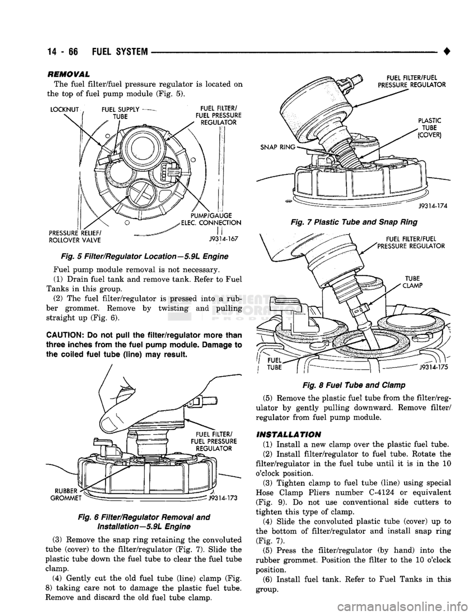
The fuel filter/fuel pressure regulator is located on
the top of fuel pump module (Fig. 5).
ROLLOVER
VALVE
J9314-167
Fig.
5 Filter/Regulator Location—5.9L
Engine
Fuel pump module removal is not necessary. (1) Drain fuel tank and remove tank. Refer to Fuel
Tanks in this group. (2) The fuel filter/regulator is pressed into a rub
ber grommet. Remove by twisting and pulling straight up (Fig. 6).
CAUTION;
Do not pull the
filter/regulator
more
than
three
inches
from
the
fuel
pump
module.
Damage
to
the
coiled
fuel
tube
(line)
may
result.
Fig.
6 Filter/Regulator
Removal
and Installation—5.9L
Engine
(3) Remove the snap ring retaining the convoluted
tube (cover) to the filter/regulator (Fig. 7). Slide the
plastic tube down the fuel tube to clear the fuel tube clamp.
(4) Gently cut the old fuel tube (line) clamp (Fig.
8) taking care not to damage the plastic fuel tube.
Remove and discard the old fuel tube clamp.
Fig.
7 Plastic Tube and
Snap
Ring
Fig.
8
Fuel
Tube and
Clamp
(5) Remove the plastic fuel tube from the filter/reg
ulator by gently pulling downward. Remove filter/
regulator from fuel pump module.
INSTALLATION
(1) Install a new clamp over the plastic fuel tube.
(2) Install filter/regulator to fuel tube. Rotate the
filter/regulator in the fuel tube until it is in the 10 o'clock position. (3) Tighten clamp to fuel tube (line) using special
Hose Clamp Pliers number C-4124 or equivalent (Fig. 9). Do not use conventional side cutters to
tighten this type of clamp.
(4) Slide the convoluted plastic tube (cover) up to
the bottom of filter/regulator and install snap ring (Fig. 7).
(5) Press the filter/regulator (by hand) into the
rubber grommet. Position the filter to the 10 o'clock
position.
(6) Install fuel tank. Refer to Fuel Tanks in this
group.
Page 904 of 1502
•
FUEL SYSTEM
14-85 to pass through it, but prevents moisture (water)
from doing so. Moisture collects at the bottom of the
separator filter.
WARNING:
EXTINGUISH
ALL
SMOKING
MATERI
ALS
BEFORE
DRAINING
THE
FUEL/WATER
SEPA
RATOR
FILTER.
There is a drain at the bottom of the separator fil
ter (Fig. 16). Place a drain pan under the drain tube.
With the engine not running, push up on the drain
to remove the water from the separator filter. Hold
the drain open until all water and contaminants
have been removed and clean fuel exits the drain. Dispose of mixture in drain pan according to applica
ble regulations.
Refer to the maintenance schedules in Group 0 in
this manual for the recommended fuel/water separa
tor filter replacement intervals.
KSB
SOLENOID
The KSB solenoid is not an output of the PCM. The
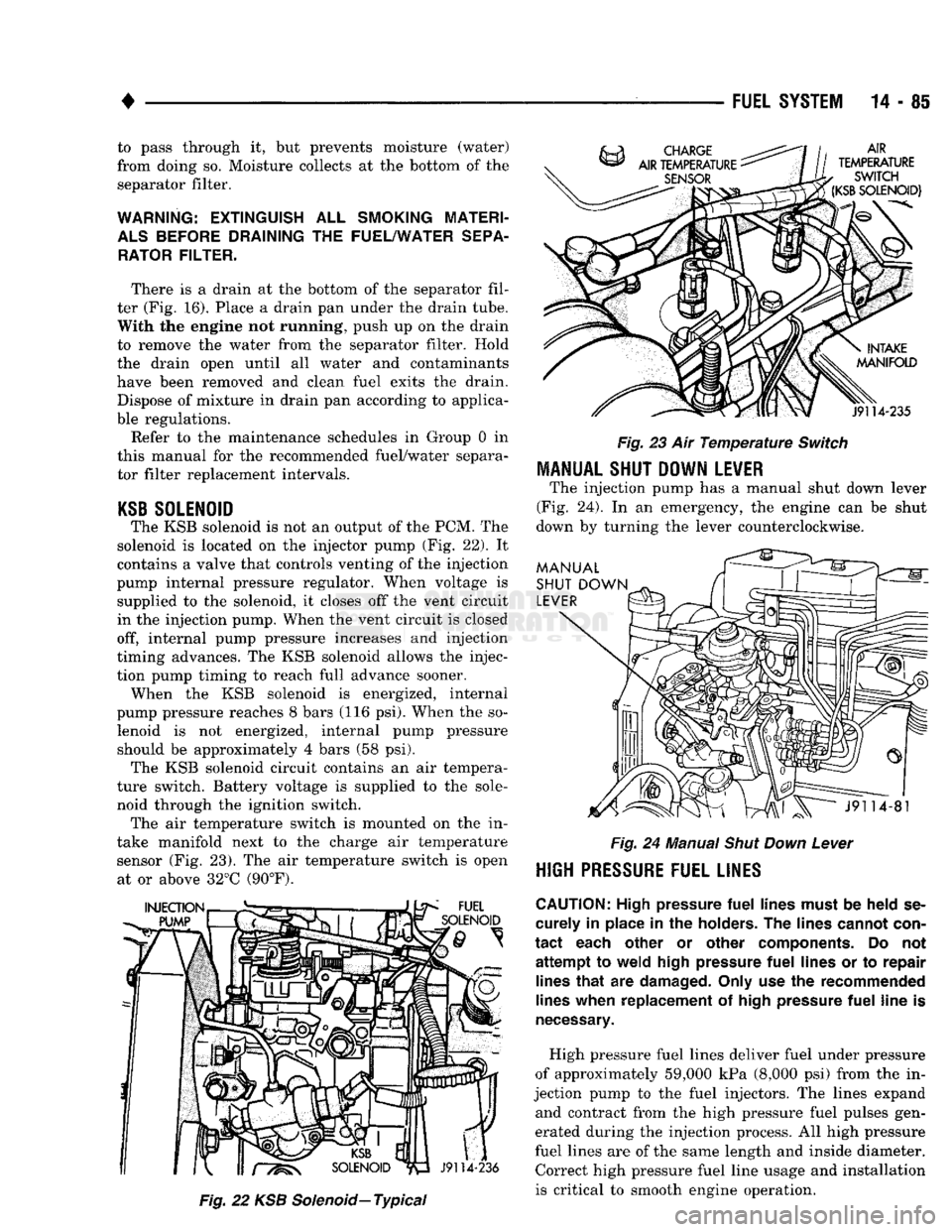
solenoid is located on the injector pump (Fig. 22). It
contains a valve that controls venting of the injection
pump internal pressure regulator. When voltage is supplied to the solenoid, it closes off the vent circuit
in the injection pump. When the vent circuit is closed
off, internal pump pressure increases and injection
timing advances. The KSB solenoid allows the injec
tion pump timing to reach full advance sooner. When the KSB solenoid is energized, internal
pump pressure reaches 8 bars (116 psi). When the so lenoid is not energized, internal pump pressure should be approximately 4 bars (58 psi). The KSB solenoid circuit contains an air tempera
ture switch. Battery voltage is supplied to the sole
noid through the ignition switch. The air temperature switch is mounted on the in
take manifold next to the charge air temperature sensor (Fig. 23). The air temperature switch is open at or above 32°C (90°F).
Fig.
22 KSB
Solenoid—
Typical
Fig.
23 Air
Temperature
Switch
MANUAL SHUT DOWN LEVER
The injection pump has a manual shut down lever
(Fig. 24). In an emergency, the engine can be shut
down by turning the lever counterclockwise.
Fig.
24 Manual
Shut
Down
Lever
HIGH
PRESSURE FUEL LINES
CAUTION:
High pressure
fuel
lines must
be
held
se
curely
in
place
in the
holders.
The
lines cannot con
tact
each other
or
other components.
Do not
attempt
to
weld high pressure
fuel
lines
or to
repair lines
that
are
damaged. Only use
the
recommended
lines when replacement
of
high pressure
fuel
line
is
necessary.
High pressure fuel lines deliver fuel under pressure
of approximately 59,000 kPa (8,000 psi) from the in
jection pump to the fuel injectors. The lines expand and contract from the high pressure fuel pulses gen
erated during the injection process. All high pressure
fuel lines are of the same length and inside diameter. Correct high pressure fuel line usage and installation
is critical to smooth engine operation.
Page 932 of 1502
•
Fig.
24 Separating
Pump
Gear from injection
Pump
Shaft
barring tool while lightly pushing in on the timing
pin. Stop when the timing pin engages the index hole
in the camshaft gear.
(2) Disengage the timing pin from the camshaft
gear. (3) Install a new injection pump gasket.
The shaft of a new or reconditioned pump is locked
in place. The key is positioned to align with the drive
gear slot when cylinder No. 1 is at TDC on the com
pression stroke.
CAUTION:
Be
sure
that
the injection
pump
shaft
key-way
does
not
fall
into the
gear
housing
when
installing
the injection
pump.
The
key-way
must
be
removed
if it
falls
into the
gear
housing.
(4) Install the injection pump. Finger tighten the
mounting nuts. The pump must be able to move in
the slot.
(5) Remove the T-bar from the injection pump
gear.
(6) Install pump drive shaft gear retaining nut and
spring washer. The injection pump will rotate
slightly if the pump mounting nuts were installed
finger tight and the crankshaft does not move.
(7) Tighten injection pump drive shaft gear retain
ing nut to 15-20
Nth
(11-15 ft. lbs.) torque. Do not
over tighten. This is not the final tightening
torque.
(8) If installing original injection pump, rotate
pump to align timing marks. If installing a new or
rebuilt pump without a timing mark, take up gear lash by rotating pump counterclockwise towards cyl
inder head.
(9) Tighten injection pump mounting nuts to 24
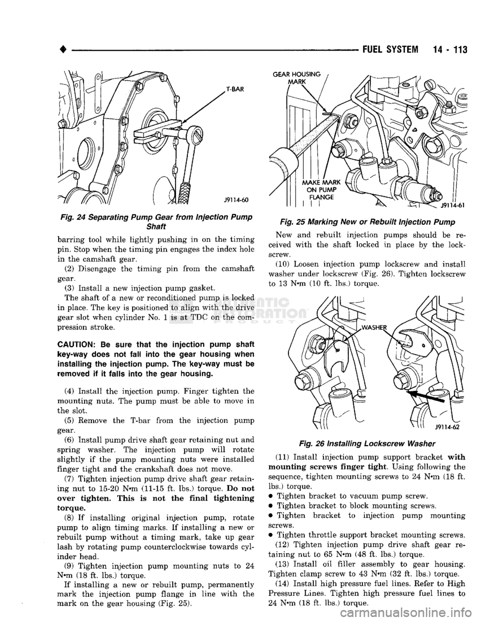
Nnn (18 ft. lbs.) torque. If installing a new or rebuilt pump, permanently
mark the injection pump flange in line with the
mark on the gear housing (Fig. 25).
FUEL
SYSTEM
14 - 113
Fig.
25 Marking New or Rebuilt Injection
Pump
New and rebuilt injection pumps should be re
ceived with the shaft locked in place by the lock- screw.
(10) Loosen injection pump lockscrew and install
washer under lockscrew (Fig. 26). Tighten lockscrew to 13 Nnn (10 ft. lbs.) torque.
Fig.
26 Installing
Lockscrew
Washer
(11) Install injection pump support bracket with
mounting screws finger tight. Using following the sequence, tighten mounting screws to 24 Nnn (18 ft.
lbs.) torque.
• Tighten bracket to vacuum pump screw.
• Tighten bracket to block mounting screws. • Tighten bracket to injection pump mounting
screws.
• Tighten throttle support bracket mounting screws. (12) Tighten injection pump drive shaft gear re
taining nut to 65 N*m (48 ft. lbs.) torque.
(13) Install oil filler assembly to gear housing.
Tighten clamp screw to 43 Nnn (32 ft. lbs.) torque.
(14) Install high pressure fuel lines. Refer to High
Pressure Lines. Tighten high pressure fuel lines to 24 Nnn (18 ft. lbs.) torque.