1993 DODGE TRUCK clock
[x] Cancel search: clockPage 1239 of 1502
21
- 238
TRANSMISSION
0VERHAUL-42RH
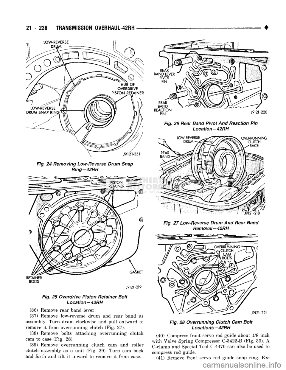
Fig. 24
Removing
Low-Reverse
Drum
Snap
Ring-42RH
RETAINER
BOLTS
J9121-219
Fig. 25 Overdrive
Piston
Retainer
Bolt
Location—42RH
(36)
Remove rear
band
lever.
(37)
Remove low-reverse drum and rear band as
assembly. Turn drum clockwise and pull outward to
remove it from overrunning clutch (Fig. 27). (38) Remove bolts attaching overrunning clutch
cam to case (Fig. 28).
(39) Remove overrunning clutch cam and roller
clutch assembly as a unit (Fig. 29). Turn cam back
and forth and tilt it inward to remove it from case.
Fig.
26 Rear
Band
Pivot And Reaction Pin
Location—42RH
Fig.
27
Low-Reverse
Drum
And Rear
Band
Removal—42RH
Fig.
28 Overrunning
Clutch
Cam
Bolt
Locations—42RH
(40) Compress front servo rod guide about 1/8 inch
with Valve Spring Compressor
C-3422-B
(Fig. 30). A C-clamp and Special Tool C-4470 can also be used to
compress rod guide. (41) Remove front servo rod guide snap ring. Ex-
Page 1270 of 1502
•
TRANSMISSION
OVERHAUL-42RH
21 - 269 must be performed properly and in the correct se
quence. Line pressure is adjusted first and throttle
pressure is adjusted last.
Line
Pressure
Adjustment
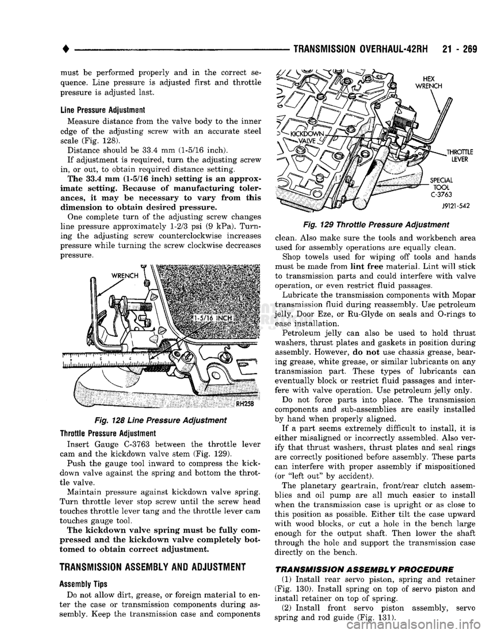
Measure distance from the valve body to the inner
edge of the adjusting screw with an accurate steel
scale (Fig. 128).
Distance should be 33.4 mm (1-5/16 inch).
If adjustment is required, turn the adjusting screw
in, or out, to obtain required distance setting. The 33.4 mm (1-5/16 inch) setting is an approx
imate setting. Because of manufacturing toler
ances,
it may be necessary to vary from this
dimension to obtain desired pressure.
One complete turn of the adjusting screw changes
line pressure approximately 1-2/3 psi (9 kPa). Turn
ing the adjusting screw counterclockwise increases
pressure while turning the screw clockwise decreases
pressure.
Fig.
128
Line
Pressure
Adjustment
Throttle
Pressure
Adjustment Insert Gauge C-3763 between the throttle lever
cam and the kickdown valve stem (Fig. 129).
Push the gauge tool inward to compress the kick-
down valve against the spring and bottom the throt
tle valve.
Maintain pressure against kickdown valve spring.
Turn throttle lever stop screw until the screw head
touches throttle lever tang and the throttle lever cam
touches gauge tool.
The kickdown valve spring must be fully com
pressed and the kickdown valve completely bot
tomed to obtain correct adjustment.
TRANSMISSION ASSEMBLY AND ADJUSTMENT
Assembly
Tips
Do not allow dirt, grease, or foreign material to en
ter the case or transmission components during as sembly. Keep the transmission case and components
Fig.
129
Throttie
Pressure
Adjustment
clean. Also make sure the tools and workbench area
used for assembly operations are equally clean.
Shop towels used for wiping off tools and hands
must be made from lint free material. Lint will stick
to transmission parts and could interfere with valve operation, or even restrict fluid passages.
Lubricate the transmission components with Mopar
transmission fluid during reassembly. Use petroleum
jelly, Door Eze, or Ru-Glyde on seals and O-rings to ease installation.
Petroleum jelly can also be used to hold thrust
washers, thrust plates and gaskets in position during assembly. However, do not use chassis grease, bear
ing grease, white grease, or similar lubricants on any
transmission part. These types of lubricants can eventually block or restrict fluid passages and inter
fere with valve operation. Use petroleum jelly only.
Do not force parts into place. The transmission
components and sub-assemblies are easily installed
by hand when properly aligned.
If a part seems extremely difficult to install, it is
either misaligned or incorrectly assembled. Also ver
ify that thrust washers, thrust plates and seal rings are correctly positioned before assembly. These parts
can interfere with proper assembly if mispositioned (or "left out" by accident).
The planetary geartrain, front/rear clutch assem
blies and oil pump are all much easier to install
when the transmission case is upright or as close to
this position as possible. Either tilt the case upward
with wood blocks, or cut a hole in the bench large enough for the output shaft. Then lower the shaft
through the hole and support the transmission case
directly on the bench.
TRANSMISSION ASSEMBLY PROCEDURE
(1) Install rear servo piston, spring and retainer
(Fig. 130). Install spring on top of servo piston and
install retainer on top of spring.
(2) Install front servo piston assembly, servo
spring and rod guide (Fig. 131).
Page 1272 of 1502
•
Fig.
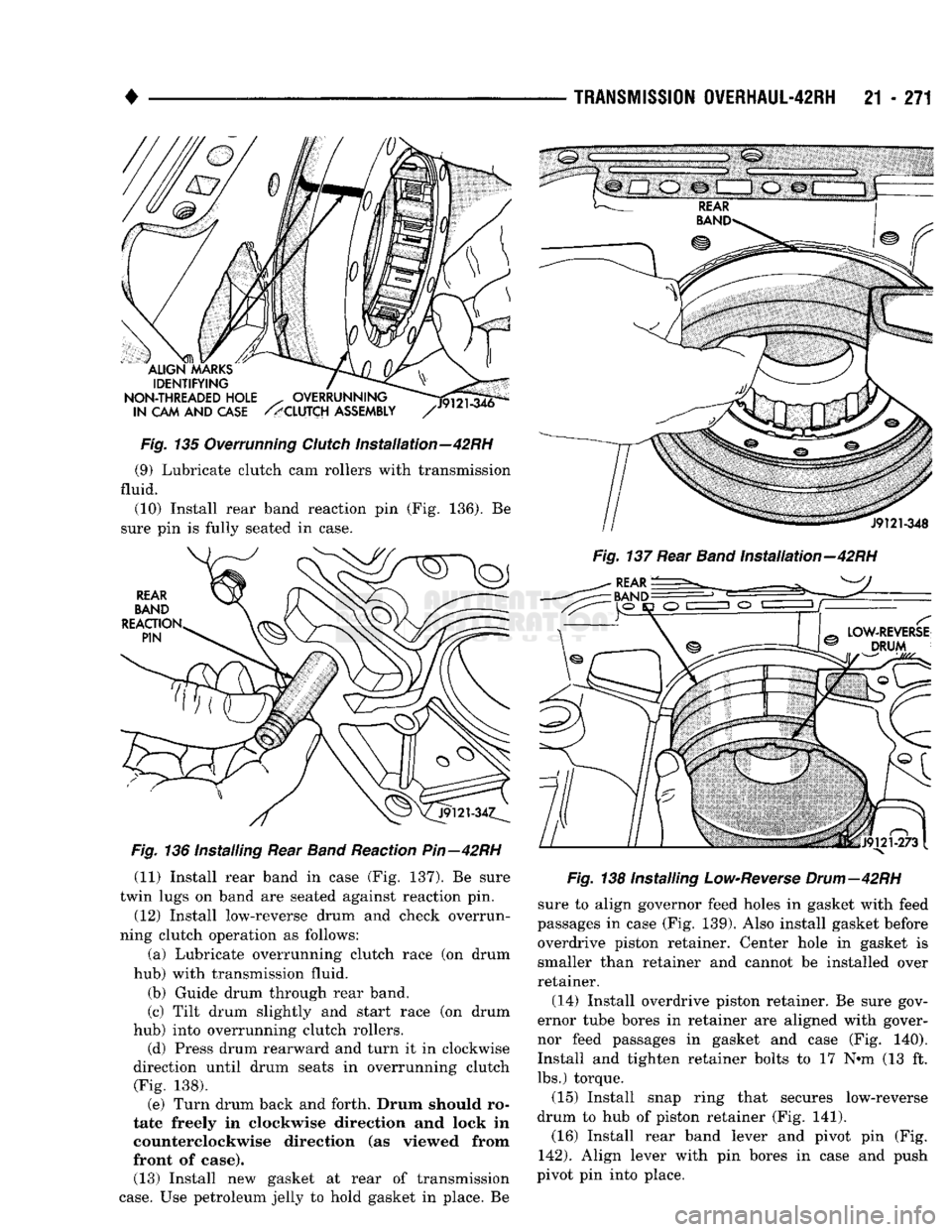
135 Overrunning
Clutch
Installation—42RH (9) Lubricate clutch cam rollers with transmission
fluid.
(10) Install rear band reaction pin (Fig. 136). Be
sure pin is fully seated in case.
Fig.
136 Installing Rear
Band
Reaction
Pin—42RH
(11) Install rear band in case (Fig. 137). Be sure
twin lugs on band are seated against reaction pin.
(12) Install low-reverse drum and check overrun
ning clutch operation as follows:
(a) Lubricate overrunning clutch race (on drum
hub) with transmission fluid.
(b) Guide drum through rear band.
(c) Tilt drum slightly and start race (on drum
hub) into overrunning clutch rollers. (d) Press drum rearward and turn it in clockwise
direction until drum seats in overrunning clutch (Fig. 138). (e) Turn drum back and forth. Drum should ro
tate freely in clockwise direction and lock in
counterclockwise direction (as viewed from
front of case). (13) Install new gasket at rear of transmission
case.
Use petroleum jelly to hold gasket in place. Be
TRANSMISSION
0VERHAUL-42RH
21 - 271
Fig.
137 Rear
Band
Installation—42RH
Fig.
138 Installing
Low-Reverse
Drum—42RH
sure to align governor feed holes in gasket with feed
passages in case (Fig. 139). Also install gasket before overdrive piston retainer. Center hole in gasket is
smaller than retainer and cannot be installed over
retainer.
(14) Install overdrive piston retainer. Be sure gov
ernor tube bores in retainer are aligned with gover
nor feed passages in gasket and case (Fig. 140).
Install and tighten retainer bolts to 17 N#m (13 ft. lbs.) torque.
(15) Install snap ring that secures low-reverse
drum to hub of piston retainer (Fig. 141). (16) Install rear band lever and pivot pin (Fig.
142).
Align lever with pin bores in case and push
pivot pin into place.
Page 1289 of 1502
21
- 288
TRANSMISSION OVERHAUL-48RH
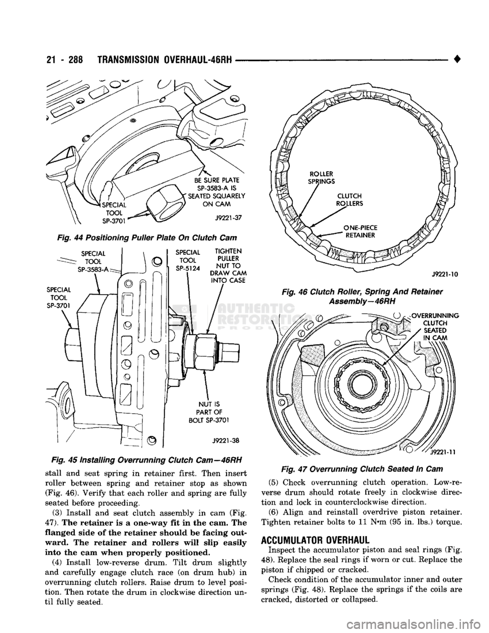
Fig.
44
Positioning
Puller
Plate
On
Clutch
Cam
Fig.
45 Installing Overrunning
Clutch
Cam—46RH
stall and seat spring in retainer first. Then insert
roller between spring and retainer stop as shown (Fig. 46). Verify that each roller and spring are fully
seated before proceeding.
(3) Install and seat clutch assembly in cam (Fig.
47).
The retainer is a one-way fit in the cam. The
flanged side of the retainer should be facing out ward. The retainer and rollers will slip easily
into the cam when properly positioned.
(4) Install low-reverse drum. Tilt drum slightly
and carefully engage clutch race (on drum hub) in
overrunning clutch rollers. Raise drum to level posi
tion. Then rotate the drum in clockwise direction un
til fully seated. •
Fig.
47 Overrunning
Clutch
Seated In Cam (5) Check overrunning clutch operation. Low-re
verse drum should rotate freely in clockwise direc
tion and lock in counterclockwise direction.
(6) Align and reinstall overdrive piston retainer.
Tighten retainer bolts to 11 N*m (95 in. lbs.) torque.
ACCUMULATOR OVERHAUL
Inspect the accumulator piston and seal rings (Fig.
48).
Replace the seal rings if worn or cut. Replace the
piston if chipped or cracked. Check condition of the accumulator inner and outer
springs (Fig. 48). Replace the springs if the coils are
cracked, distorted or collapsed.
Page 1315 of 1502
21
- 314
TRANSMISSION
OVERHAUL-46RH
—
•
Fig.
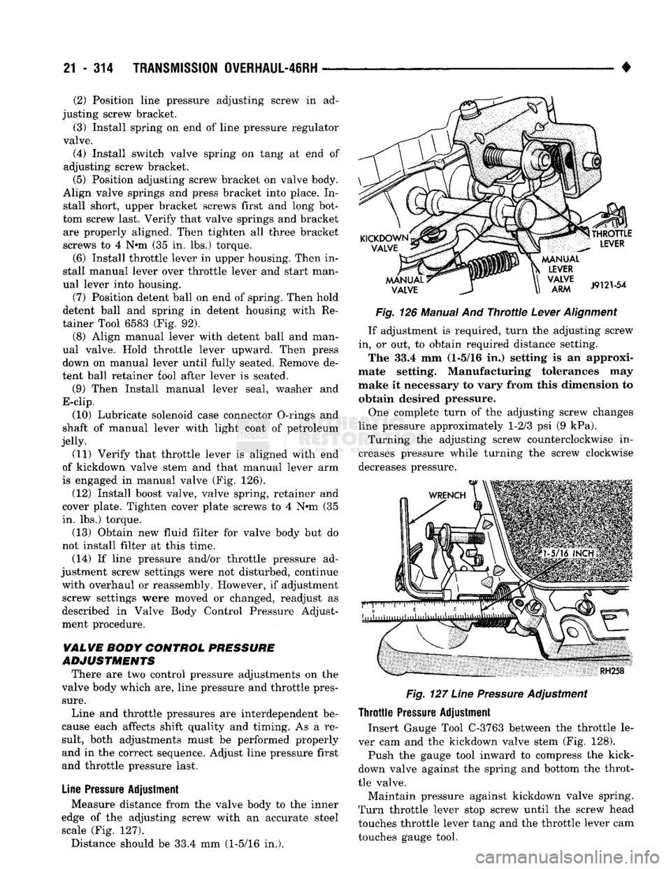
126 Manual And
Throttle
Lever
Alignment
If adjustment is required, turn the adjusting screw
in, or out, to obtain required distance setting. The 33.4 mm (1-5/16 in.) setting is an approxi
mate setting. Manufacturing tolerances may
make it necessary to vary from this dimension to obtain desired pressure.
One complete turn of the adjusting screw changes
line pressure approximately 1-2/3 psi (9 kPa). Turning the adjusting screw counterclockwise in
creases pressure while turning the screw clockwise
decreases pressure.
Fig.
127
Line
Pressure
Adjustment
Throttle
Pressure
Adjustment Insert Gauge Tool C-3763 between the throttle le
ver cam and the kickdown valve stem (Fig. 128).
Push the gauge tool inward to compress the kick-
down valve against the spring and bottom the throt
tle valve.
Maintain pressure against kickdown valve spring.
Turn throttle lever stop screw until the screw head
touches throttle lever tang and the throttle lever cam
touches gauge tool.
(2) Position line pressure adjusting screw in ad
justing screw bracket.
(3) Install spring on end of line pressure regulator
valve. (4) Install switch valve spring on tang at end of
adjusting screw bracket. (5) Position adjusting screw bracket on valve body.
Align valve springs and press bracket into place. In stall short, upper bracket screws first and long bot
tom screw last. Verify that valve springs and bracket are properly aligned. Then tighten all three bracket
screws to 4 N*m (35 in. lbs.) torque.
(6) Install throttle lever in upper housing. Then in
stall manual lever over throttle lever and start man
ual lever into housing.
(7) Position detent ball on end of spring. Then hold
detent ball and spring in detent housing with Re
tainer Tool 6583 (Fig. 92). (8) Align manual lever with detent ball and man
ual valve. Hold throttle lever upward. Then press
down on manual lever until fully seated. Remove de
tent ball retainer fool after lever is seated.
(9) Then Install manual lever seal, washer and
E-clip.
(10) Lubricate solenoid case connector O-rings and
shaft of manual lever with light coat of petroleum
jelly. (11) Verify that throttle lever is aligned with end
of kickdown valve stem and that manual lever arm
is engaged in manual valve (Fig. 126).
(12) Install boost valve, valve spring, retainer and
cover plate. Tighten cover plate screws to 4 N»m (35
in. lbs.) torque.
(13) Obtain new fluid filter for valve body but do
not install filter at this time.
(14) If line pressure and/or throttle pressure ad
justment screw settings were not disturbed, continue with overhaul or reassembly. However, if adjustment screw settings were moved or changed, readjust as
described in Valve Body Control Pressure Adjust
ment procedure.
VALVE
BODY
CONTROL
PRESSURE
ADJUSTMENTS
There are two control pressure adjustments on the
valve body which are, line pressure and throttle pres
sure.
Line and throttle pressures are interdependent be
cause each affects shift quality and timing. As a re
sult, both adjustments must be performed properly and in the correct sequence. Adjust line pressure first
and throttle pressure last.
Line
Pressure
Adjustment Measure distance from the valve body to the inner
edge of the adjusting screw with an accurate steel scale (Fig. 127). Distance should be 33.4 mm (1-5/16 in.).
Page 1329 of 1502
21
- 328
OVERDRIVE UNIT OVERHAUL—42RH/46RH
•
Fig.
21 Removing/Installing Output Shaft Front Bearing WARNING: THE NEXT STEP IN GEARTRAIN
DISASSEMBLY INVOLVES COMPRESSING THE DI
RECT CLUTCH SPRING. IT IS EXTREMELY IMPOR
TANT THAT PROPER EQUIPMENT BE USED TO COMPRESS THE SPRING AS SPRING FORCE IS
APPROXIMATELY 800 POUNDS. USE SPRING COM PRESSOR TOOL C-6227-1 AND A HYDRAULIC-
TYPE SHOP PRESS WITH A MINIMUM RAM
TRAVEL OF 5-6 INCHES. THE PRESS MUST ALSO HAVE A BED THAT CAN BE ADJUSTED UP OR
DOWN AS REQUIRED. RELEASE CLUTCH SPRING
TENSION SLOWLY AND COMPLETELY TO AVOID PERSONAL INJURY.
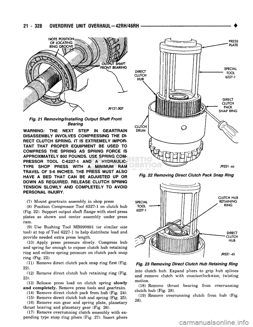
(7) Mount geartrain assembly in shop press
(8) Position Compressor Tool 6227-1 on clutch hub
(Fig. 22). Support output shaft flange with steel press
plates as shown and center assembly under press ram.
(9) Use Bushing Tool MB990891 (or similar size
tool) at top of Tool 6227-1 to help distribute load and
provide needed extra press length.
(10) Apply press pressure slowly. Compress hub
and spring far enough to expose clutch hub retaining
ring and relieve spring pressure on clutch pack snap
ring (Fig. 22).
(11) Remove direct clutch pack snap ring first (Fig.
22).
(12) Remove direct clutch hub retaining ring (Fig.
23).
(13) Release press load on clutch spring slowly
and completely. Remove press tools and geartrain. (14) Remove direct clutch pack from hub (Fig. 24). (15) Remove direct clutch hub and spring (Fig. 25).
(16) Remove sun gear and spring plate, planetary
thrust bearing and planetary gear (Fig. 26). (17) Remove overrunning clutch assembly with ex
panding type snap ring pliers (Fig. 27). Insert pliers
Fig.
22
Removing
Direct
Clutch
Pack
Snap
Ring
Fig.
23
Removing
Direct
Clutch
Hub Retaining
Ring
into clutch hub. Expand pliers to grip hub splines and remove clutch with counterclockwise, twisting
motion.
(18) Remove thrust bearing from overrunning
clutch hub (Fig. 28). (19) Remove overrunning clutch from hub (Fig.
28).
Page 1335 of 1502
21
- 334
OVERDRIVE
UNIT
OVERHAUL—42RH/46RH
•
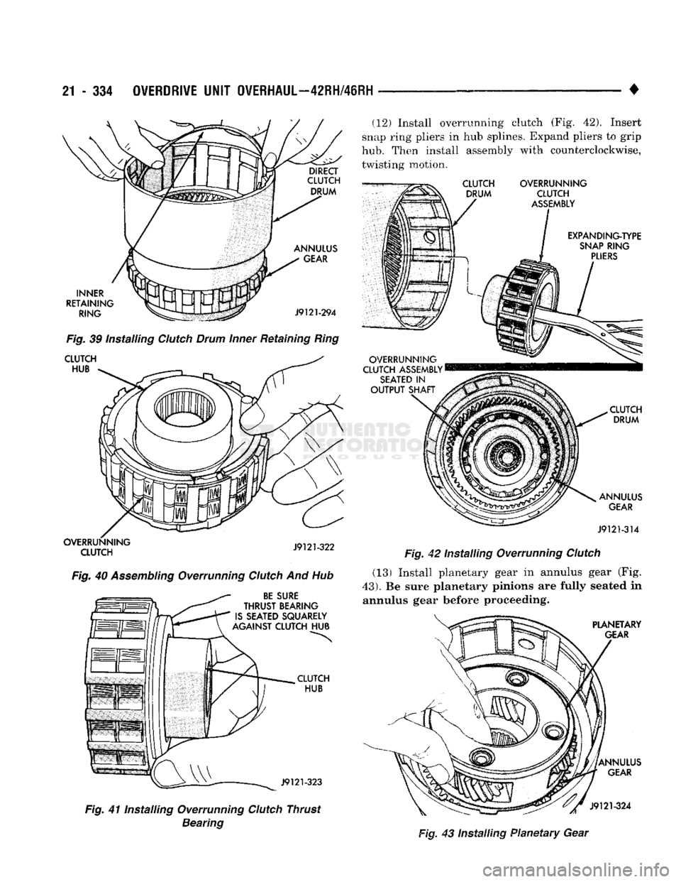
INNER
RETAINING RING ANNULUS
GEAR
J9121-294
Fig.
39 installing
Clutch
Drum
Inner
Retaining
Ring
CLUTCH HUB OVERRUNNING
CLUTCH
J9121-322
Fig.
40
Assembling
Overrunning
Clutch
And Hub
BE
SURE
THRUST
BEARING
IS
SEATED SQUARELY
AGAINST CLUTCH
HUB
CLUTCH HUB
J9121-323
Fig.
41 Installing Overrunning
Clutch
Thrust
Bearing
(12) Install overrunning clutch (Fig. 42). Insert
snap
ring
pliers in hub splines. Expand pliers to grip
hub.
Then install assembly with counterclockwise, twisting motion.
CLUTCH
DRUM OVERRUNNING
CLUTCH
ASSEMBLY
EXPAN DING-TYPE
SNAP
RING
PLIERS
OVERRUNNING
CLUTCH ASSEMBLY
SEATED
IN
OUTPUT
SHAFT
CLUTCH DRUM
ANNULUS
GEAR
J9121-314
Fig.
42 Installing Overrunning
Clutch
(13) Install planetary gear in annulus gear (Fig.
43).
Be sure planetary pinions are fully seated in annulus gear before proceeding.
PLANETARY
GEAR
ANNULUS
GEAR
J9121-324
Fig.
43 Installing Planetary Gear
Page 1354 of 1502
•
NP241 TRANSFER
CASE
21 - 313
LOCK OIL RING SEAL
ADAPTER
(OVERDRIVE
ONLY)
SPEEDOMETER
PINION
GEAR
ADAPTER
O-RING
SPEEDOMETER
ADAPTER
RETAINER
DISTANCE
SENSOR
J9021-99
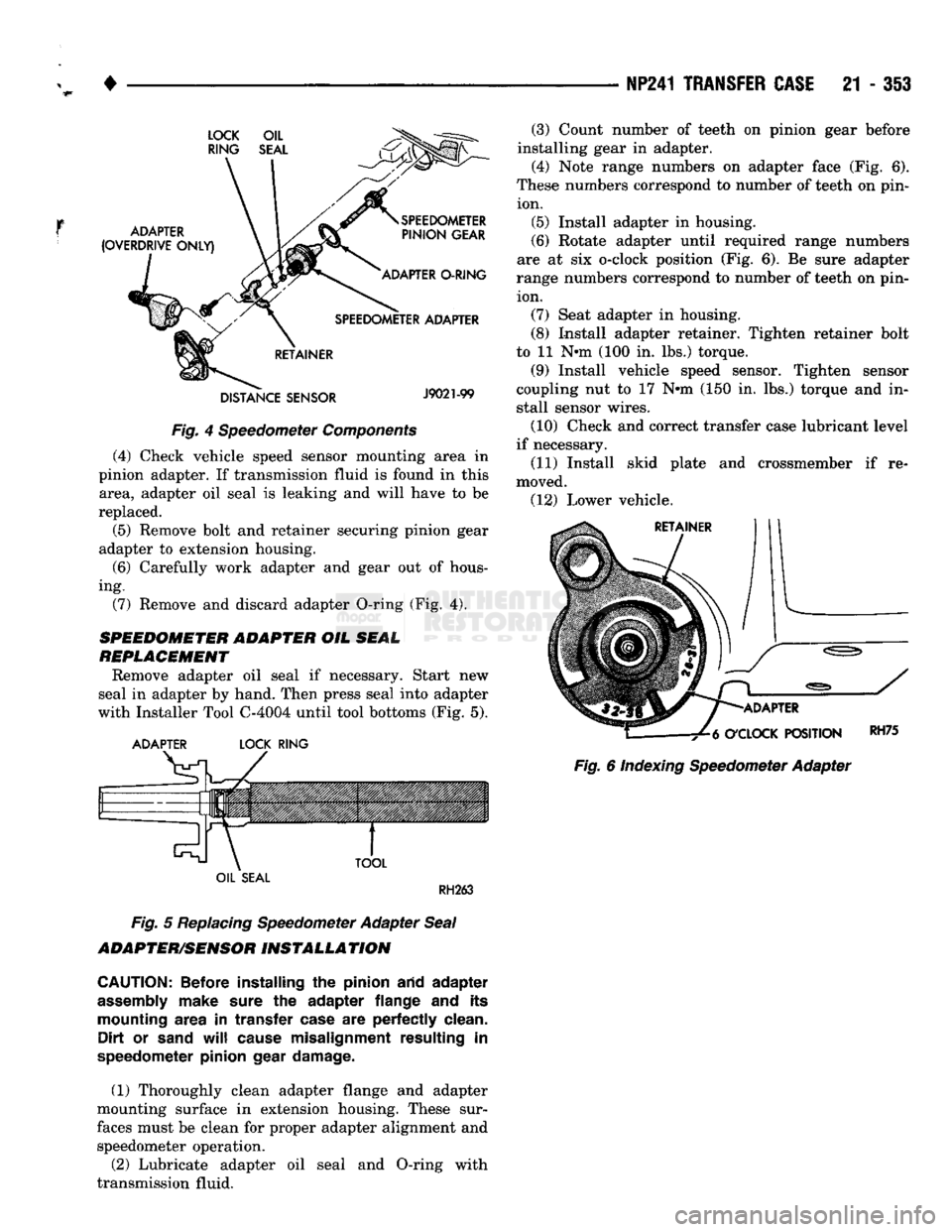
Fig.
4 Speedometer
Components
(4) Check vehicle speed sensor mounting area in
pinion adapter. If transmission fluid is found in this area, adapter oil seal is leaking and will have to be
replaced.
(5) Remove bolt and retainer securing pinion gear
adapter to extension housing.
(6)
Carefully work adapter and gear out of hous
ing. (7) Remove and discard adapter O-ring (Fig. 4).
SPEEDOMETER ADAPTER
OIL
SEAL
REPLACEMENT
Remove adapter oil seal if necessary. Start new
seal in adapter by hand. Then press seal into adapter
with Installer Tool C-4004 until tool bottoms (Fig. 5).
ADAPTER
LOCK
RING
TOOL
(3) Count number of teeth on pinion gear before
installing gear in adapter.
(4) Note range numbers on adapter face (Fig. 6).
These numbers correspond to number of teeth on pin ion. (5) Install adapter in housing.
(6)
Rotate adapter until required range numbers
are at six o-clock position (Fig. 6). Be sure adapter
range numbers correspond to number of teeth on pin ion. (7) Seat adapter in housing.
(8) Install adapter retainer. Tighten retainer bolt
to 11 N-m (100 in. lbs.) torque.
(9) Install vehicle speed sensor. Tighten sensor
coupling nut to 17 N-m (150 in. lbs.) torque and in
stall sensor wires.
(10) Check and correct transfer case lubricant level
if necessary.
(11) Install skid plate and crossmember if re
moved. (12) Lower vehicle.
ADAPTER
O'CLOCK
POSITION
Fig.
6 Indexing Speedometer Adapter
RH75
OIL
SEAL
RH263
Fig.
5
Replacing
Speedometer Adapter
Seal
ADAPTER/SENSOR
INSTALLATION
CAUTION:
Before installing
the
pinion arid adapter
assembly
make sure
the
adapter flange
and its
mounting area
in
transfer case
are
perfectly clean. Dirt
or
sand
will
cause misalignment resulting
in
speedometer pinion gear damage.
(1) Thoroughly clean adapter flange and adapter
mounting surface in extension housing. These sur
faces must be clean for proper adapter alignment and speedometer operation.
(2) Lubricate adapter oil seal and O-ring with
transmission fluid.