1993 DODGE TRUCK clock
[x] Cancel search: clockPage 1141 of 1502
21
• 140
IN-VEHICLE
SERVICE-32RH/36RH/37RH/42RH/46RH
•
VALVE BODY CONTROL
PRESSURE
ADJUSTMENTS
There
are two
control pressure adjustments
on the
valve body which
are:
Line pressure
and
throttle pres
sure.
The valve body must
be
removed from
the
transmission
in
order
to
perform
the
adjust
ments. Refer
to the
valve body removal/installa
tion procedures
in
this section. Because line
and
throttle pressures
are
interdepen
dent (each affects shift quality
and
timing), both
ad
justments must
be
performed properly
and in the
correct sequence. Adjust line pressure first
and
throt
tle pressure last.
LINE
PRESSURE
ADJUSTMENT
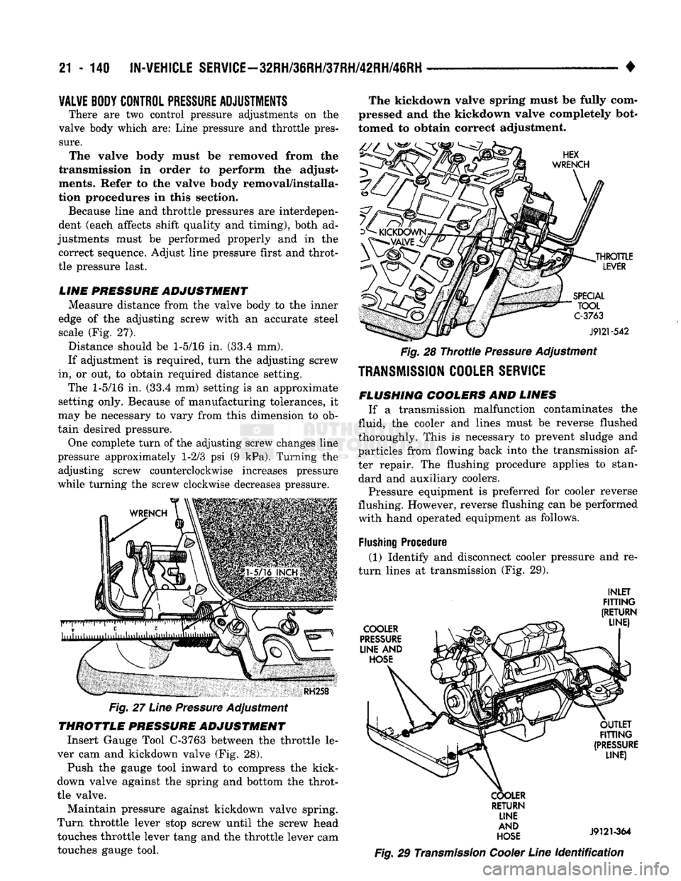
Measure distance from
the
valve body
to the
inner
edge
of the
adjusting screw with
an
accurate steel scale
(Fig. 27).
Distance should
be 1-5/16 in. (33.4 mm).
If adjustment
is
required, turn
the
adjusting screw
in,
or out, to
obtain required distance setting.
The
1-5/16 in. (33.4 mm)
setting
is an
approximate
setting only. Because
of
manufacturing tolerances,
it
may
be
necessary
to
vary from this dimension
to ob
tain desired pressure.
One complete turn
of the
adjusting screw changes line
pressure approximately
1-2/3 psi (9 kPa).
Turning
the
adjusting screw counterclockwise increases pressure
while turning
the
screw clockwise decreases pressure.
RH258
Fig.
27
Line
Pressure
Adjustment
THROTTLE
PRESSURE
ADJUSTMENT
Insert Gauge Tool C-3763 between
the
throttle
le
ver
cam and
kickdown valve
(Fig. 28).
Push
the
gauge tool inward
to
compress
the
kick-
down valve against
the
spring
and
bottom
the
throt
tle valve. Maintain pressure against kickdown valve spring.
Turn throttle lever stop screw until
the
screw head touches throttle lever tang
and the
throttle lever
cam
touches gauge tool. The kickdown valve spring must
be
fully com
pressed
and the
kickdown valve completely bot
tomed
to
obtain correct adjustment.
HEX
WRENCH
^
KICKDOWN
yL£_
THROTTLE
LEVER
SPECIAL
" TOOL C-3763
J9121-542
Fig.
28
Throttle
Pressure
Adjustment
TRANSMISSION
COOLER
SERVICE
FLUSHING
COOLERS
AND
LINES
If
a
transmission malfunction contaminates
the
fluid, the cooler
and
lines must
be
reverse flushed
thoroughly. This
is
necessary
to
prevent sludge
and
particles from flowing back into
the
transmission
af
ter repair.
The
flushing procedure applies
to
standard
and
auxiliary coolers.
Pressure equipment
is
preferred
for
cooler reverse
flushing. However, reverse flushing
can be
performed with hand operated equipment
as
follows.
Flushing
Procedure (1) Identify
and
disconnect cooler pressure
and re
turn lines
at
transmission
(Fig. 29).
INLET
FITTING
(RETURN
_ LINE)
COOLER
^
PRESSURE
LINE
AND
HOSE OUTLET
FITTING
(PRESSURE LINE)
COOLER RETURN LINE
AND
HOSE
J9121-364
Fig.
29
Transmission
Cooler
Line
Identification
Page 1143 of 1502
!1
- 142
AUTOMATIC TRANSMISSION REMOVAL
AND
INSTALLATION
• AUTOMATIC TRANSMISSION REMOWAL AND INSTALLATION
INDEX
page
Dverdrlve
Unit
Installation
150
Overdrive
Unit
Removal-42RH/46RH
........ 149
Pump
Oil
Seal
146
Starter
Ring Gear Replacement
144
Torque Converter
and
Drive
Plate
Service
..... 144
Transmission
and
Torque Converter
Installation—
2-Wheel Drive
146
page
Transmission
and
Torque Converter
Installation—
4-Wheel Drive
. . .' 148
Transmission
and
Torque Converter Removal— 2-Wheel Drive
142
Transmission
and
Torque Converter Removal
—
4-Wheel Drive
143
TRANSMISSION
AND
TORQUE CONVERTER REMOVAL—2-WHEEL DRIVE The
transmission and torque converter should
be removed as an assembly to avoid component damage. The converter drive plate, pump bush
ing, or oil seal can be damaged if the converter
is left attached to the driveplate during removal. Be sure to remove the transmission and con
verter as an assembly.
(1) Raise vehicle.
(2) Disconnect or remove exhaust components as
needed for service access.
(3) Remove engine-to-transmission struts, if
equipped. (4) Disconnect fluid cooler lines at transmission.
(5) Remove starter motor and cooler line bracket.
(6) Remove torque converter bolt access cover.
(7) Remove transmission oil pan, drain fluid and
reinstall pan. (8) Remove transmission fill tube bracket bolts and
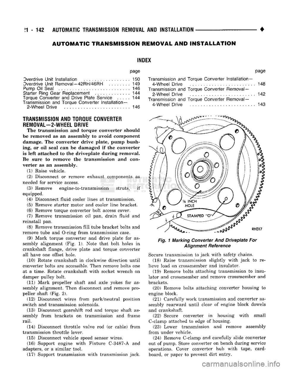
remove tube and O-ring from transmission case. (9) Mark torque converter and drive plate for as
sembly alignment (Fig. 1). Note that bolt holes in
crankshaft flange, drive plate and torque converter
all have one offset hole. (10) Rotate crankshaft in clockwise direction until
converter bolts are accessible. Then remove bolts one at a time. Rotate crankshaft with socket wrench on
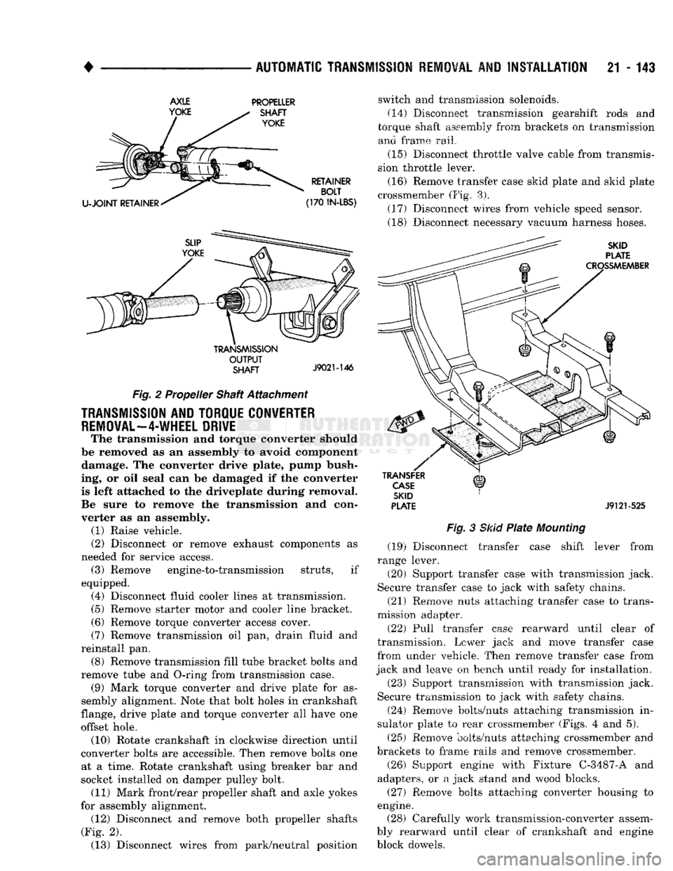
damper pulley bolt. (11) Mark propeller shaft and axle yokes for as
sembly alignment. Then disconnect and remove pro
peller shaft (Fig. 2). (12) Disconnect wires from park/neutral position
switch and transmission solenoids. (13) Disconnect gearshift rod and torque shaft as
sembly from brackets on transmission and frame
rail.
(14) Disconnect throttle valve rod (or cable) from
transmission throttle lever. (15) Disconnect vehicle speed sensor wires.
(16) Support engine with Fixture C-3487-A and
adapters, or a similar tool. (17) Support transmission with transmission jack.
Fig.
1 Marking Converter And
Driveplate
For
Alignment
Reference Secure transmission to jack with safety chains.
(18) Raise transmission slightly with jack to re
lieve load on crossmember and insulator. (19) Remove bolts attaching transmission to insu
lator and crossmember and remove crossmember and
brackets. (20) Remove bolts attaching converter housing to
engine block.
(21) Carefully work transmission and converter as
sembly rearward until clear of engine block dowels and crankshaft. (22) Secure converter in housing with small
C-clamp attached to edge of housing. (23) Lower transmission and remove assembly
from under vehicle.
(24) Remove C-clamp and carefully slide converter
out of pump. Store converter on bench during service
operations. Cover converter hub with tape, card
board, or paper to prevent dirt entry.
Page 1144 of 1502
•
AUTOMATIC TRANSMISSION REMOVAL
AND
INSTALLATION
21 - 143
AXLE
YOKE PROPELLER
SHAFT
YOKE
U-JOINT
RETAINER RETAINER
BOLT
(170
IN-LBS)
TRANSMISSION
OUTPUT
SHAFT
J9021-146
Fig.
2 Propeller Shaft Attachment
TRANSMISSION
AND TORQUE CONVERTER
REMOVAL—4-WHEEL
DRIVE
The transmission and torque converter should
be removed as an assembly to avoid component damage. The converter drive plate, pump bush
ing, or oil seal can be damaged if the converter
is left attached to the driveplate during removal.
Be sure to remove the transmission and con
verter as an assembly. (1) Raise vehicle.
(2) Disconnect or remove exhaust components as
needed for service access. (3) Remove engine-to-transmission struts, if
equipped. (4) Disconnect fluid cooler lines at transmission. (5) Remove starter motor and cooler line bracket.
(6) Remove torque converter access cover.
(7) Remove transmission oil pan, drain fluid and
reinstall pan. (8) Remove transmission fill tube bracket bolts and
remove tube and O-ring from transmission case. (9) Mark torque converter and drive plate for as
sembly alignment. Note that bolt holes in crankshaft
flange, drive plate and torque converter all have one
offset hole. (10) Rotate crankshaft in clockwise direction until
converter bolts are accessible. Then remove bolts one at a time. Rotate crankshaft using breaker bar and
socket installed on damper pulley bolt. (11) Mark front/rear propeller shaft and axle yokes
for assembly alignment. (12) Disconnect and remove both propeller shafts
(Fig. 2). (13) Disconnect wires from park/neutral position switch and transmission solenoids.
(14)
Disconnect transmission gearshift rods and
torque shaft assembly from brackets on transmission and frame rail.
(15) Disconnect throttle valve cable from transmis
sion throttle lever.
(16) Remove transfer case skid plate and skid plate
crossmember (Fig. 3). (17) Disconnect wires from vehicle speed sensor.
(18) Disconnect necessary vacuum harness hoses.
SKID
PLATE
CROSSMEMBER
TRANSFER
CASE
SKID
PLATE
J9121-525
Fig.
3
Skid
Plate
Mounting
(19) Disconnect transfer case shift lever from
range lever.
(20) Support transfer case with transmission jack.
Secure transfer case to jack with safety chains.
(21) Remove nuts attaching transfer case to trans
mission adapter.
(22) Pull transfer case rearward until clear of
transmission. Lower jack and move transfer case
from under vehicle. Then remove transfer case from
jack and leave on bench until ready for installation.
(23) Support transmission with transmission jack.
Secure transmission to jack with safety chains.
(24) Remove bolts/nuts attaching transmission in
sulator plate to rear crossmember (Figs. 4 and 5).
(25) Remove bolts/nuts attaching crossmember and
brackets to frame rails and remove crossmember.
(26) Support engine with Fixture C-3487-A and
adapters, or a jack stand and wood blocks.
(27) Remove bolts attaching converter housing to
engine. (28) Carefully work transmission-converter assem
bly rearward until clear of crankshaft and engine
block dowels.
Page 1160 of 1502
•
TRANSMISSION
OVERHAUL—32RH
21 - 159 ASSEMBLING OVERRUNNING
CLUTCH/LOW*
REVERSE DRUM (1) Assemble clutch rollers and springs in retainer
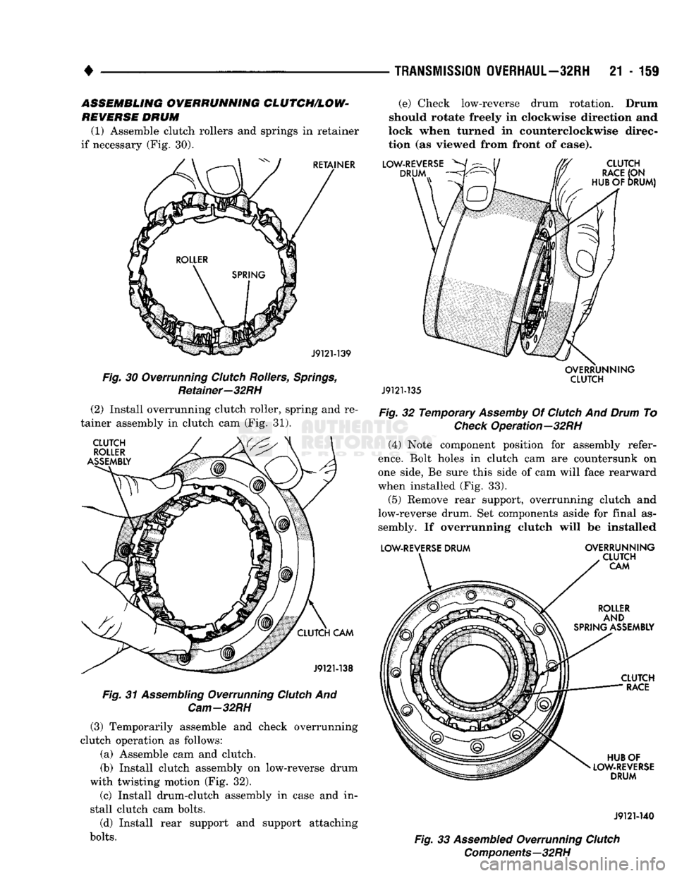
if necessary (Fig. 30).
RETAINER
J9121-139
Fig.
30 Overrunning
Clutch
Rollers,
Springs,
Retainer—32RH (2) Install overrunning clutch roller, spring and re
tainer assembly in clutch cam (Fig. 31).
CLUTCH
ROLLER
ASSEMBLY
CLUTCH
CAM
J9121-138
Fig.
31
Assembling
Overrunning
Clutch
And
Cam-32RH
(3) Temporarily assemble and check overrunning
clutch operation as follows:
(a) Assemble cam and clutch.
(b) Install clutch assembly on low-reverse drum
with twisting motion (Fig. 32).
(c) Install drum-clutch assembly in case and in
stall clutch cam bolts.
(d) Install rear support and support attaching
bolts.
(e) Check low-reverse drum rotation. Drum
should rotate freely in clockwise direction and
lock when turned in counterclockwise direc
tion (as viewed from front of case).
LOW-REVERSE
^/
DRUM
CLUTCH
RACE
(ON
HUB OF
DRUM)
OVERRUNNING
CLUTCH
J9121-135
Fig.
32 Temporary
Assemby
Of
Clutch
And
Drum
To
Check
Operation—32RH (4) Note component position for assembly refer
ence.
Bolt holes in clutch cam are countersunk on
one side, Be sure this side of cam will face rearward
when installed (Fig. 33).
(5) Remove rear support, overrunning clutch and
low-reverse drum. Set components aside for final as
sembly. If overrunning clutch will be installed
LOW-REVERSE
DRUM
OVERRUNNING
CLUTCH
CAM
ROLLER
AND
SPRING ASSEMBLY
CLUTCH
RACE
HUB OF
LOW-REVERSE
DRUM
J9121-140
Fig.
33
Assembled
Overrunning
Clutch
Components—32RH
Page 1185 of 1502
21 - 184
TRANSMISSION
OVERHAUL—32RH
-
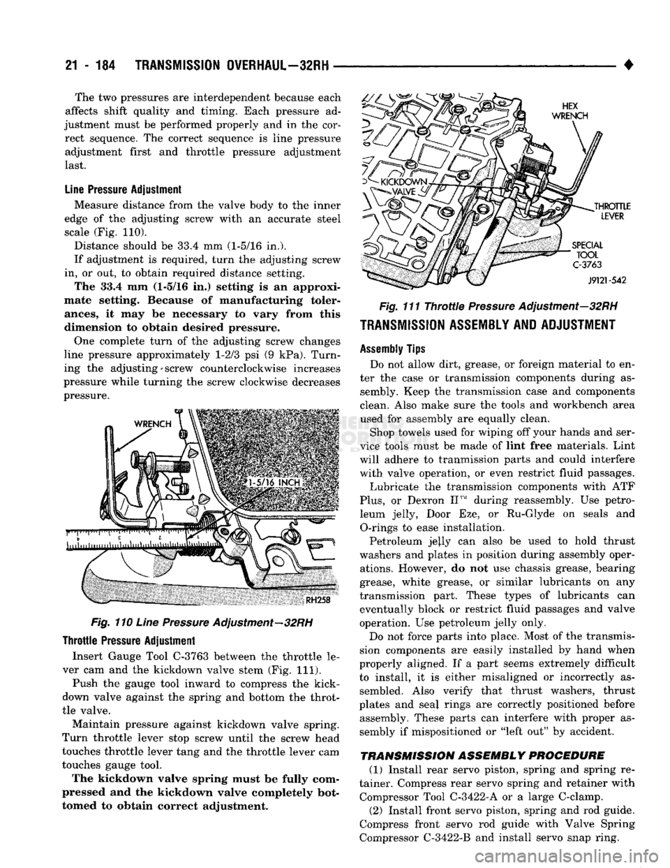
Fig. 110 Line Pressure Adjustment—32RH
Throttle
Pressure
Adjustment
Insert Gauge Tool C-3763 between the throttle le
ver cam and the kickdown valve stem (Fig. 111).
Push the gauge tool inward to compress the kick-
down valve against the spring and bottom the throt
tle valve.
Maintain pressure against kickdown valve spring.
Turn throttle lever stop screw until the screw head
touches throttle lever tang and the throttle lever cam
touches gauge tool.
The kickdown valve spring must be fully com
pressed and the kickdown valve completely bot
tomed to obtain correct adjustment.
•
Fig. 111 Throttle Pressure Adjustment—32RH
TRANSMISSION ASSEMBLY AND ADJUSTMENT
Assembly
Tips
Do not allow dirt, grease, or foreign material to en
ter the case or transmission components during as sembly. Keep the transmission case and components
clean. Also make sure the tools and workbench area
used for assembly are equally clean.
Shop towels used for wiping off your hands and ser
vice tools must be made of lint free materials. Lint
will adhere to tranmission parts and could interfere with valve operation, or even restrict fluid passages.
Lubricate the transmission components with ATF
Plus,
or Dexron II™ during reassembly. Use petro leum jelly, Door Eze, or Ru-Glyde on seals and O-rings to ease installation.
Petroleum jejly can also be used to hold thrust
washers and plates in position during assembly oper ations. However, do not use chassis grease, bearing
grease, white grease, or similar lubricants on any
transmission part. These types of lubricants can eventually block or restrict fluid passages and valve
operation. Use petroleum jelly only.
Do not force parts into place. Most of the transmis
sion components are easily installed by hand when
properly aligned. If a part seems extremely difficult
to install, it is either misaligned or incorrectly as sembled. Also verify that thrust washers, thrust
plates and seal rings are correctly positioned before assembly. These parts can interfere with proper as
sembly if mispositioned or "left out" by accident.
TRANSMISSION
ASSEMBLY PROCEDURE (1) Install rear servo piston, spring and spring re
tainer. Compress rear servo spring and retainer with Compressor Tool C-3422-A or a large C-clamp.
(2) Install front servo piston, spring and rod guide.
Compress front servo rod guide with Valve Spring
Compressor C-3422-B and install servo snap ring.
The two pressures are interdependent because each
affects shift quality and timing. Each pressure ad
justment must be performed properly and in the cor rect sequence. The correct sequence is line pressure adjustment first and throttle pressure adjustment
last.
Line
Pressure
Adjustment
Measure distance from the valve body to the inner
edge of the adjusting screw with an accurate steel
scale (Fig. 110).
Distance should be 33.4 mm (1-5/16 in.).
If adjustment is required, turn the adjusting screw
in, or out, to obtain required distance setting.
The 33.4 mm (1-5/16 in,) setting Is an approxi
mate setting. Because of manufacturing toler
ances,
it may be necessary to vary from this
dimension to obtain desired pressure.
One complete turn of the adjusting screw changes
line pressure approximately 1-2/3 psi (9 kPa). Turn
ing the adjusting-screw counterclockwise increases
pressure while turning the screw clockwise decreases
pressure.
Page 1186 of 1502
•
TRANSMISSION
OVERHAUL—32RH
21-185
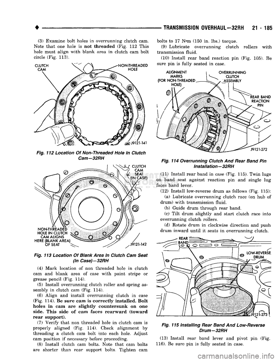
(3) Examine bolt holes in overrunning clutch cam.
Note that one hole is not threaded (Fig. 112 This
hole must align with blank area in clutch cam bolt circle (Fig. 113).
Fig.
113 Location Of
Blank
Area in
Clutch
Cam
Seat
(in
Case)-32RH
(4) Mark location of non threaded hole in clutch
cam and blank area of case with paint stripe or
grease pencil (Fig. 114).
(5) Install overrunning clutch roller and spring as
sembly in clutch cam (Fig. 114).
(6) Align and install overrunning clutch in case
(Fig. 114). Be sure cam is correctly installed. Bolt
holes in cam are slightly countersunk on one side. This side of cam faces rearward (toward
rear support).
(7) Verify that non threaded hole in clutch cam is
properly aligned (Fig. 114). Check alignment by threading a clutch cam bolt into each hole. Adjust cam position if necessary before proceeding.
(8) Install clutch cam bolts. Note that cam bolts
are shorter than rear support bolts. Tighten cam bolts to 17 N»m (150 in. lbs.) torque.
(9) Lubricate overrunning clutch rollers with
transmission fluid. (10) Install rear band reaction pin (Fig. 105). Be
sure pin is fully seated in case.
Fig.
114 Overrunning
Clutch
And Rear
Band
Pin Installation—32RH
(11) Install rear band in case (Fig. 115). Twin lugs
on band seat against reaction pin and single lug
faces band lever.
(12) Install low-reverse drum as follows (Fig. 115): (a) Lubricate overrunning clutch race (on hub of
drum) with transmission fluid. (b) Guide drum through rear band.
(c) Tilt drum slightly and start clutch race into
overrunning clutch rollers.
(d) Rotate drum in clockwise direction and push
drum inward until it seats in overrunning clutch.
Fig.
115 Installing Rear
Band
And
Low-Reverse
Drum—32RH
(13) Install rear band lever and pivot pin (Fig.
116).
Be sure pin is fully seated in case.
Page 1208 of 1502
TRANSMISSION
OVERHAUL—36RH/37RH
21 - 207
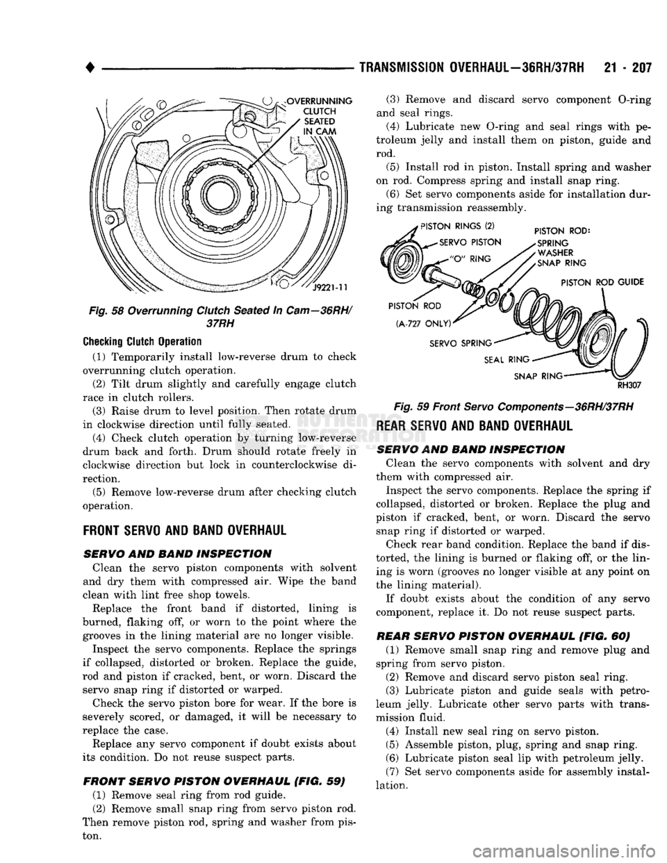
Fig.
58 Overrunning Clutch Seated in
Cam—36RH/
37RH
Checking
Clutch
Operation
(1) Temporarily install low-reverse drum to check
overrunning clutch operation.
(2) Tilt drum slightly and carefully engage clutch
race in clutch rollers.
(3) Raise drum to level position. Then rotate drum
in clockwise direction until fully seated.
(4) Check clutch operation by turning low-reverse
drum back and forth. Drum should rotate freely in
clockwise direction but lock in counterclockwise di
rection.
(5) Remove low-reverse drum after checking clutch
operation.
FRONT
SERVO
AND BAND OVERHAUL
SERVO
AND BAND INSPECTION Clean the servo piston components with solvent
and dry them with compressed air. Wipe the band
clean with lint free shop towels.
Replace the front band if distorted, lining is
burned, flaking off, or worn to the point where the grooves in the lining material are no longer visible.
Inspect the servo components. Replace the springs
if collapsed, distorted or broken. Replace the guide,
rod and piston if cracked, bent, or worn. Discard the servo snap ring if distorted or warped.
Check the servo piston bore for wear. If the bore is
severely scored, or damaged, it will be necessary to
replace the case.
Replace any servo component if doubt exists about
its condition. Do not reuse suspect parts.
FRONT SERVO PISTON OVERHAUL (FIG. 59) (1) Remove seal ring from rod guide.
(2) Remove small snap ring from servo piston rod.
Then remove piston rod, spring and washer from pis
ton. (3) Remove and discard servo component O-ring
and seal rings.
(4)
Lubricate new O-ring and seal rings with pe
troleum jelly and install them on piston, guide and rod.
(5) Install rod in piston. Install spring and washer
on rod. Compress spring and install snap ring.
(6) Set servo components aside for installation dur
ing transmission reassembly.
RH307
Fig.
59 Front
Servo
Components—36RH/37RH
REAR SERVO
AND BAND OVERHAUL
SERVO AND BAND INSPECTION Clean the servo components with solvent and dry
them with compressed air.
Inspect the servo components. Replace the spring if
collapsed, distorted or broken. Replace the plug and
piston if cracked, bent, or worn. Discard the servo snap ring if distorted or warped.
Check rear band condition. Replace the band if dis
torted, the lining is burned or flaking off, or the lin ing is worn (grooves no longer visible at any point on
the lining material).
If doubt exists about the condition of any servo
component, replace it. Do not reuse suspect parts.
REAR SERVO PISTON OVERHAUL (FIG. 60) (1) Remove small snap ring and remove plug and
spring from servo piston.
(2) Remove and discard servo piston seal ring.
(3) Lubricate piston and guide seals with petro
leum jelly. Lubricate other servo parts with trans
mission fluid.
(4) Install new seal ring on servo piston.
(5) Assemble piston, plug, spring and snap ring. (6) Lubricate piston seal lip with petroleum jelly.
(7) Set servo components aside for assembly instal
lation.
Page 1224 of 1502
•
TRANSMISSION
OVERHAUL—36RH/37RH
21 - 223 (16) Align and install governor plug end plate
(Fig. 99) on valve body and install end plate screws.
Tighten screws to 4 N»m (35 in. lbs.) torque.
(17) Install manual valve (Fig. 99). (18) Install throttle valve and spring. Then install
kickdown valve and detent (Fig. 99). (19) Install pressure regulator valve and switch
valve (Fig. 99).
(20) Install manual lever detent spring in housing.
Place detent ball on end of spring and push ball and spring into housing. Secure ball and spring with Re
tainer Tool 6583 (Fig. 88).
(21) Insert line pressure adjusting screw in adjust
ing screw bracket (Fig. 92).
(22) Place valve spring on end of line pressure reg
ulator valve.
(23) Install switch valve spring on tang at end of
adjusting screw bracket (Fig. 87). (24) Install adjusting screw bracket on valve body.
Align springs, press bracket toward valve body and install long bottom bracket attaching screw first. Do
not tighten screw fully at this time.
(25) Carefully align bracket on valve body and
transfer plate and install remaining (two) bracket screws. Verify that valve springs and bracket are
properly aligned. Then tighten all three bracket screws to 4 N*m (35 in. lbs.) torque.
(26) Install throttle lever in valve body. Then in
stall manual lever over throttle lever and start man
ual lever into valve body.
(27) Align manual lever detent with detent ball
and align lever arm with manual valve. Hold throt
tle lever upward. Then press down on manual lever until lever is fully seated.
(28) Install manual lever seal, washer and retain
ing E-clip.
(29) Lubricate shaft of manual lever with light
coat of petroleum jelly. This will help protect seal lip
when manual shaft seal is installed.
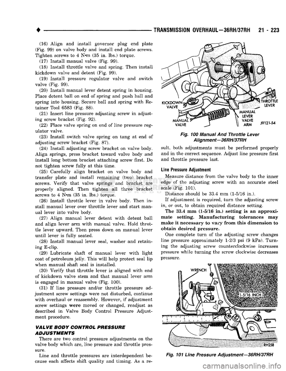
(30) Verify that throttle lever is aligned with end
of kickdown valve stem and that manual lever arm
is engaged in manual valve (Fig. 100).
(31) If line pressure and/or throttle pressure ad
justment screw settings were not disturbed, continue with overhaul or reassembly. However, if adjustment screw settings were moved or changed, readjust as
described in Valve Body Control Pressure Adjust
ment procedure.
VALVE BODY CONTROL
PRESSURE
ADJUSTMENTS
There are two control pressure adjustments on the
valve body which are, line pressure and throttle pres
sure.
Line and throttle pressures are interdependent be
cause each affects shift quality and timing. As a re-
Fig.
100 Manual And
Throttle
Lever
Alignment-36RH/37RH
suit, both adjustments must be performed properly
and in the correct sequence. Adjust line pressure first
and throttle pressure last.
Line
Pressure
Adjustment Measure distance from the valve body to the inner
edge of the adjusting screw with an accurate steel scale (Fig. 101).
Distance should be 33.4 mm (1-5/16 in.).
If adjustment is required, turn the adjusting screw
in, or out, to obtain required distance setting. The 33.4 mm (1-5/16 in.) setting is an approxi
mate setting. Manufacturing tolerances may
make it necessary to vary from this dimension to obtain desired pressure.
One complete turn of the adjusting screw changes
line pressure approximately 1-2/3 psi (9 kPa). Turn
ing the adjusting screw counterclockwise increases
pressure while turning the screw clockwise decreases
pressure.
Fig.
101
Line
Pressure
Adjustment—36RH/37RH