1993 DODGE TRUCK clock
[x] Cancel search: clockPage 939 of 1502
14-120
FUEL
SYSTEM
• move the throttle lever (by hand) from the idle posi
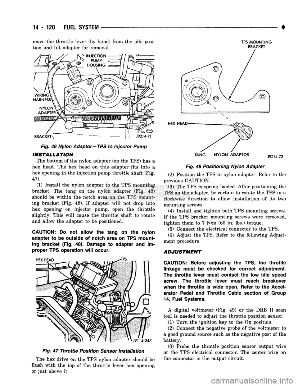
tion and lift adapter for removal. Fig. 46
Nylon
Adaptor—TPS to Injector Pump
INSTALLATION
The bottom of the nylon adapter (on the TPS) has a
hex head. The hex head on this adapter fits into a
hex opening in the injection pump throttle shaft (Fig.
47).
(1) Install the nylon adapter to the TPS mounting
bracket. The tang on the nylon adapter (Fig. 48) should be within the notch area on the TPS mount
ing bracket (Fig. 48). If adapter will not drop into
hex opening on injector pump, open the throttle slightly. This will cause the throttle shaft to rotate
and allow the adapter to be positioned.
CAUTION:
Do not allow the tang on the nylon
adapter to be outside of notch area on TPS mount
ing
bracket (Fig. 48).
Damage
to adapter and im
proper TPS operation
will
occur.
Fig.
47
Throttle
Position
Sensor
Installation
The hex drive on the TPS nylon adapter should be
flush with the top of the throttle lever hex opening or just above it.
TPS
MOUNTING
BRACKET
TANG
NYLON
ADAPTOR
Fig. 48 Positioning
Nylon
Adapter (2) Position the TPS to nylon adapter. Refer to the
previous CAUTION.
(3) The TPS is spring loaded. After positioning the
TPS on the adapter, be certain to rotate the TPS in a clockwise direction to allow installation of its two
mounting screws.
(4) Install and tighten both TPS mounting screws.
If the TPS bracket mounting screws were removed,
tighten them to 7 N»m (60 in. lbs.) torque.
(5) Connect the electrical connector to the TPS.
(6) Adjust the TPS. Refer to the following Adjust
ment procedure.
ADJUSTMENT
CAUTION:
Before adjusting the TPS, the
throttle
linkage
must
be checked for correct adjustment.
The
throttle
lever
must
contact the low idle
speed
screw.
The
throttle
lever
must
reach breakover
when the
throttle
is wide
open.
Refer to the
Accel
erator Pedal and
Throttle
Cable
section
of
Group
14,
Fuel
Systems.
A digital voltmeter (Fig. 49) or the DRB II scan
tool is needed to adjust the throttle position sensor. (1) Turn the ignition key to the On position.
(2) Connect the negative probe of the voltmeter to
a good ground source such as the negative post of the
battery.
(3) Probe the throttle position sensor output wire
at the TPS electrical connector. The center wire on
the connector is the output circuit.
Page 975 of 1502
19
- 14
STEERING
• (9) Install the fluid hoses to the power steering
pump, Tighten the pressure fitting at the pump to 30
N*m (22 ft. lbs.) torque.
(10) Install and clamp the hose on the vacuum
pump. (11) Fill the reservoir with power steering fluid
only. If necessary, refer to Pump Initial Operation
for detailed instructions.
(12) Start and run the engine. Check the operation
of the brakes, if necessary refer to Group 5, Brakes
for additional information.
PUMP REPLACEMENT—GASOLINE ENGINE
REMOVAL
WARNING:
DO NOT
REMOVE
THE
WATER PUMP COOLANT TUBE UNLESS
THE
COOLANT SYSTEM HAS BEEN DEPRESSUR1ZED
AND
DRAINED*
WARNING:
DO NOT
ATTEMPT
TO
REMOVE
THE
PUMP
WITHOUT
REMOVING
THE
BELT FIRST.
THE
AUTOMATIC TENSIONER
IS
UNDER
A
HIGH
SPRING
LOAD.
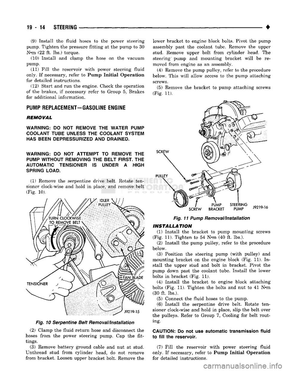
(1) Remove the serpentine drive belt. Rotate ten
sioner clock-wise and hold in place, and remove belt
(Fig. 10).
Fig.
10 Serpentine Belt Removal/Installation
(2) Clamp the fluid return hose and disconnect the
hoses from the power steering pump. Cap the fit
tings.
(3) Remove battery ground cable and nut at stud.
Unthread stud from cylinder head, do not remove
from bracket. Loosen upper bracket bolt. Remove the lower bracket to engine block bolts. Pivot the pump
assembly past the coolant tube. Remove the upper
stud. Remove upper bolt from cylinder head. The
steering pump and mounting bracket will be re
moved from engine as an assembly.
(4) Remove the pump pulley, refer to the procedure
below. This will allow access to the pump attaching screws.
(5)
Remove the bracket to pump attaching screws
(Fig. 11).
Fig.
11
Pump
Removal/Installation
INSTALLATION
(1) Install the bracket to pump mounting screws
(Fig. 11). Tighten to 54 N-m (40 ft. lbs.). (2) Install the pump pulley, refer to the procedure
below.
(3) Position the steering pump (with pulley) and
mounting bracket on the engine block (Fig. 11). In stall the upper stud and bolt in bracket. Pivot the
pump down past the coolant tube. Install the lower
bolts in bracket (Fig. 11). (4) Install the bracket to engine block attaching
bolts (Fig. 11). Tighten the bolts and nut to 41 N*m (30 ft. lbs.).
(5) Connect the fluid hoses to the pump. (6) Install the serpentine drive belt. Rotate ten
sioner clock-wise and hold in place, slip the belt over
the pulleys. Refer to Group 7, Cooling for belt rout ing.
CAUTION:
Do not use
automatic
transmission
fluid
to
fill the
reservoir.
(7) Fill the reservoir with power steering fluid
only. If necessary, refer to Pump Initial Operation
for detailed instructions.
Page 983 of 1502
19 - 22
STEERING
——— —
WORM THRUST BEARING PRELOAD
ADJUSTMENT
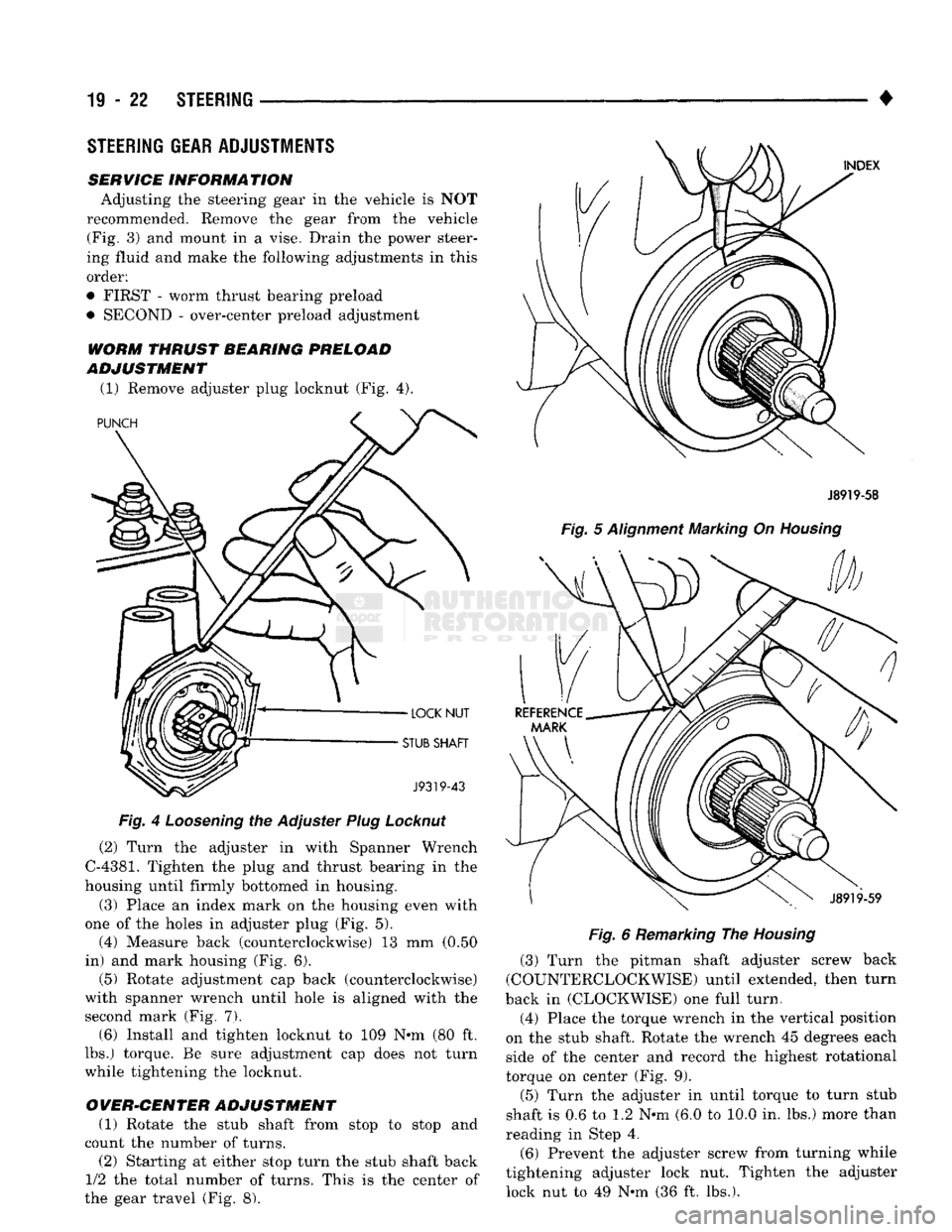
(1) Remove adjuster plug locknut (Fig. 4).
Fig.
4
Loosening
the Adjuster
Plug
Locknut
(2) Turn the adjuster in with Spanner Wrench
C-4381.
Tighten the plug and thrust bearing in the
housing until firmly bottomed in housing.
(3) Place an index mark on the housing even with
one of the holes in adjuster plug (Fig. 5). (4) Measure back (counterclockwise) 13 mm (0.50
in) and mark housing (Fig. 6). (5) Rotate adjustment cap back (counterclockwise)
with spanner wrench until hole is aligned with the
second mark (Fig. 7). (6) Install and tighten locknut to 109 N-m (80 ft.
lbs.) torque. Be sure adjustment cap does not turn
while tightening the locknut.
OVER-CENTER ADJUSTMENT (1) Rotate the stub shaft from stop to stop and
count the number of turns.
(2) Starting at either stop turn the stub shaft back
1/2 the total number of turns. This is the center of
the gear travel (Fig. 8). •
J8919-58
Fig.
5
Alignment
Marking On
Housing
Fig.
6 Remarking The
Housing
(3) Turn the pitman shaft adjuster screw back
(COUNTERCLOCKWISE) until extended, then turn
back in (CLOCKWISE) one full turn.
(4) Place the torque wrench in the vertical position
on the stub shaft. Rotate the wrench 45 degrees each
side of the center and record the highest rotational
torque on center (Fig. 9).
(5) Turn the adjuster in until torque to turn stub
shaft is 0.6 to 1.2 N-m (6.0 to 10.0 in. lbs.) more than
reading in Step 4.
(6) Prevent the adjuster screw from turning while
tightening adjuster lock nut. Tighten the adjuster lock nut to 49 N-m (36 ft. lbs.).
STEERING
GEAR
ADJUSTMENTS
SERVICE
INFORMATION
Adjusting the steering gear in the vehicle is NOT
recommended. Remove the gear from the vehicle (Fig. 3) and mount in a vise. Drain the power steer
ing fluid and make the following adjustments in this
order:
• FIRST - worm thrust bearing preload
• SECOND - over-center preload adjustment
Page 986 of 1502
•
STEERING
19 - 25
PITMAN
SHAFT AND SIDE COVER REPLACEMENT
REMOVE (1) Remove steering gear from vehicle. Refer to
Power Steering Gear Replacement in this section. (2) Remove pitman arm from steering gear. Refer
to Pitman Arm Removal in the Steering Linkage sec
tion.
(3) Rotate stub shaft back and forth to drain power
steering fluid.
DISASSEMBLE
• Clean exposed end of pitman shaft and housing.
• Clean pitman shaft spline with a wire brush.
(1) Remove preload adjuster nut.
(2) Rotate stub shaft with socket to center gear.
Remove side cover bolts. (3) Remove side cover, gasket and pitman shaft as
an assembly.
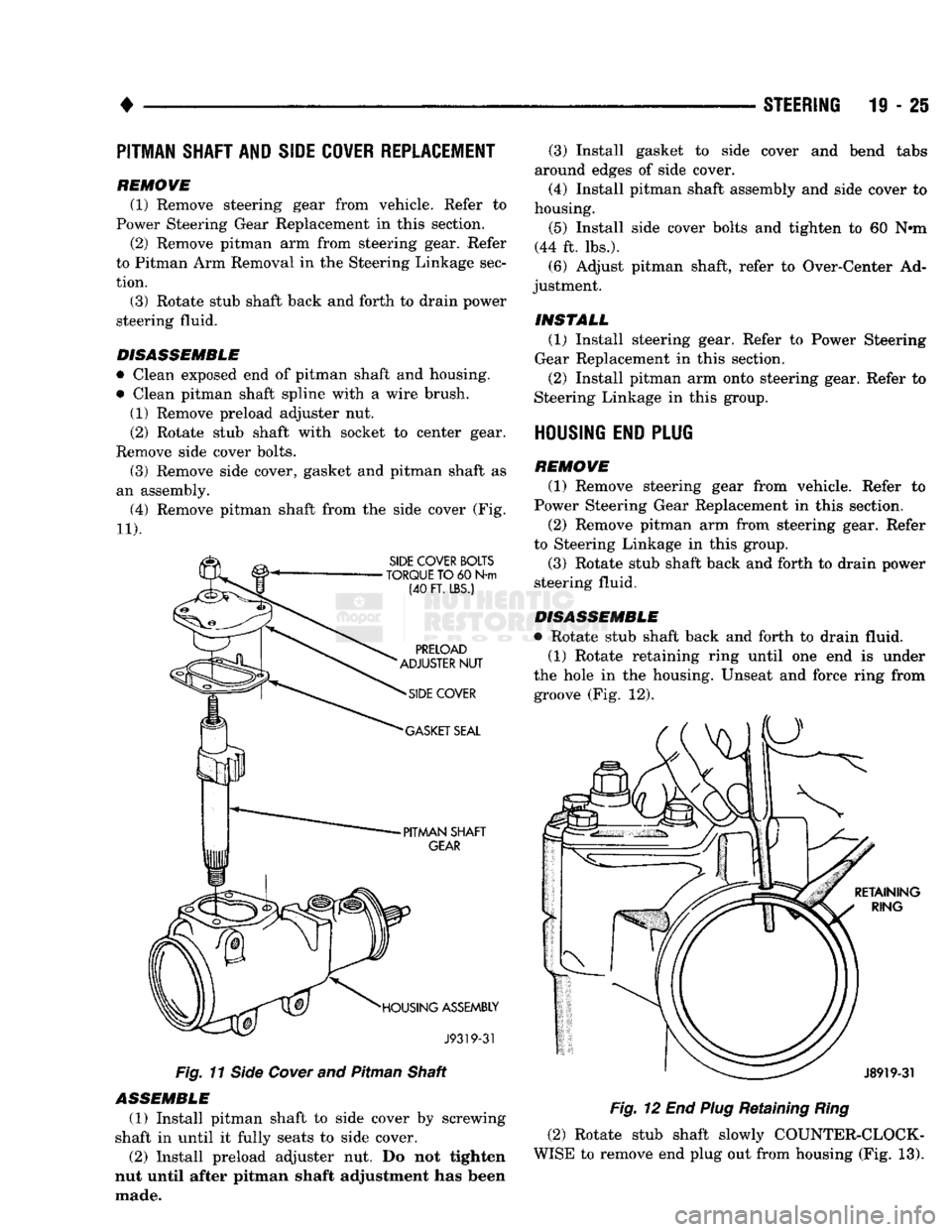
(4) Remove pitman shaft from the side cover (Fig.
11). Fig.
11
Side
Cover
and Pitman Shaft
ASSEMBLE
(1) Install pitman shaft to side cover by screwing
shaft in until it fully seats to side cover. (2) Install preload adjuster nut. Do not tighten
nut until after pitman shaft adjustment has been
made. (3) Install gasket to side cover and bend tabs
around edges of side cover.
(4) Install pitman shaft assembly and side cover to
housing.
(5) Install side cover bolts and tighten to 60 N»m
(44 ft. lbs.). (6) Adjust pitman shaft, refer to Over-Center Ad
justment.
INSTALL (1) Install steering gear. Refer to Power Steering
Gear Replacement in this section.
(2) Install pitman arm onto steering gear. Refer to
Steering Linkage in this group.
HOUSING END PLUG
REMOVE (1) Remove steering gear from vehicle. Refer to
Power Steering Gear Replacement in this section.
(2) Remove pitman arm from steering gear. Refer
to Steering Linkage in this group.
(3) Rotate stub shaft back and forth to drain power
steering fluid.
DISASSEMBLE
• Rotate stub shaft back and forth to drain fluid. (1) Rotate retaining ring until one end is under
the hole in the housing. Unseat and force ring from groove (Fig. 12).
Fig.
12 End
Plug
Retaining
Ring
(2) Rotate stub shaft slowly COUNTER-CLOCK
WISE to remove end plug out from housing (Fig. 13).
Page 990 of 1502
•
STEERING
19 - 29
RACK PISTON AND WORM SHAFT REPLACEMENT
J8919-48
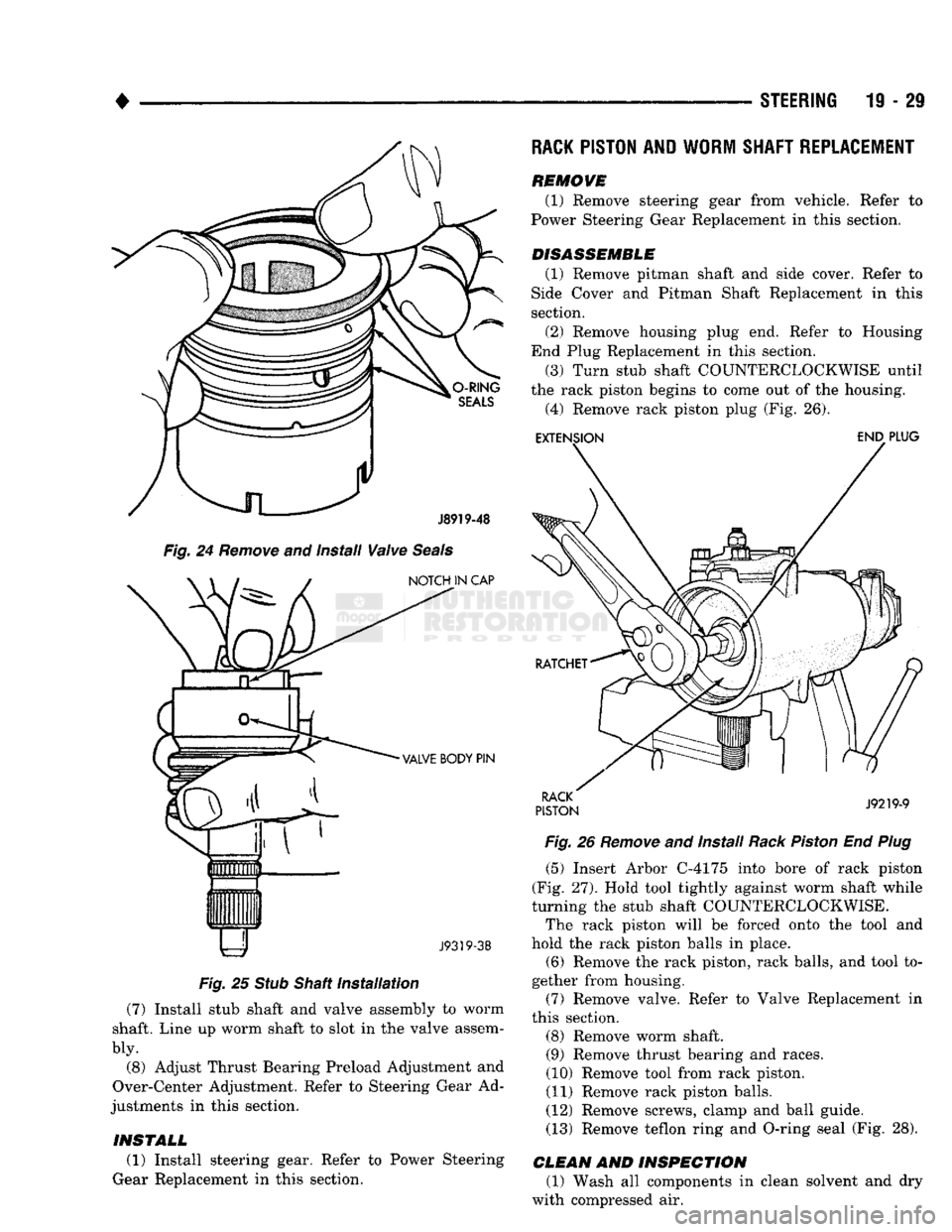
Fig.
24
Remove
and install
Valve
Seals
NOTCH IN CAP
VALVE BODY PIN
liHiiiiiim J9319-38
Fig.
25
Stub
Shaft
Installation
(7) Install stub shaft and valve assembly to worm
shaft. Line up worm shaft to slot in the valve assem
bly.
(8) Adjust Thrust Bearing Preload Adjustment and
Over-Center Adjustment. Refer to Steering Gear Ad
justments in this section. REMOVE
(1) Remove steering gear from vehicle. Refer
Power Steering Gear Replacement in this section. to
DISASSEMBLE
(1) Remove pitman shaft and side cover. Refer to
Side Cover and Pitman Shaft Replacement in this section.
(2) Remove housing plug end. Refer to Housing
End Plug Replacement in this section.
(3) Turn stub shaft COUNTERCLOCKWISE until
the rack piston begins to come out of the housing. (4) Remove rack piston plug (Fig. 26). EXTENSION END PLUG
RACK
PISTON J9219-9
Fig.
26
Remove
and Install
Rack
Piston
End
Plug
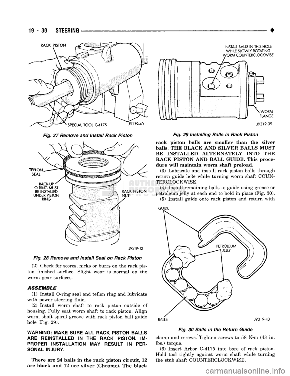
(5) Insert Arbor C-4175 into bore of rack piston
(Fig. 27). Hold tool tightly against worm shaft while
turning the stub shaft COUNTERCLOCKWISE.
The rack piston will be forced onto the tool and
hold the rack piston balls in place.
(6) Remove the rack piston, rack balls, and tool to
gether from housing. (7) Remove valve. Refer to Valve Replacement in
this section.
(8) Remove worm shaft. (9) Remove thrust bearing and races.
(10) Remove tool from rack piston.
(11) Remove rack piston balls.
(12) Remove screws, clamp and ball guide. (13) Remove teflon ring and O-ring seal (Fig. 28).
CLEAN
AND
INSPECTION
(1) Wash all components in clean solvent and dry
with compressed air.
INSTALL
(1) Install steering gear. Refer to Power Steering
Gear Replacement in this section.
Page 991 of 1502
11-30 STEERING
Fig.
27 Remove and install Rack Piston
J92T9-12
Fig. 28 Remove and Install Seal on Rack Piston (2) Check for scores, nicks or burrs on the rack pis
ton finished surface. Slight wear is normal on the
worm gear surfaces.
ASSEMBLE
(1) Install O-ring seal and teflon ring and lubricate
with power steering fluid. (2) Install worm shaft to rack piston outside of
housing. Fully seat worm shaft to rack piston. Align worm shaft spiral groove with rack piston ball guide
hole (Fig. 29).
WARNING: MAKE SURE ALL RACK PISTON BALLS ARE REINSTALLED IN THE RACK PISTON. IM PROPER INSTALLATION MAY RESULT IN PER
SONAL INJURY.
There are 24 balls in the rack piston circuit, 12
are Mack and 12 are silver (Chrome). The black w
INSTALL BALLS IN THIS HOLE WHILE SLOWLY ROTATING
WORM COUNTERCLOCKWISE
J9319-39
Fig.
29 Installing
Balls
in
Rack
Piston
rack piston balls are smaller than the silver
balls.
THE BLACK AND SILVEE BALLS MUST
BE INSTALLED ALT1ENATELY INTO THE
RACK PISTON AND BALL GUIDE. This proce
dure will maintain worm shaft preload. (3) Lubricate and install rack piston balls through
return guide hole while turning worm shaft COUN
TERCLOCKWISE.
(4) Install remaining balls to guide using grease or
petroleum jelly at each end to hold in place (Fig. 30). (5) Install guide onto rack piston and return with
GUIDE
BALLS J9319-40 Fig.
30
Balls
in the Return
Guide
clamp and screws. Tighten screws to 58 N#m (43 in. lbs.) torque. (6) Insert Arbor C-4175 into bore of rack piston.
Hold tool tightly against worm shaft while turning
the stub shaft COUNTERCLOCKWISE.
Page 992 of 1502
•
STEERING
19 - 31 The rack piston will be forced onto the tool and
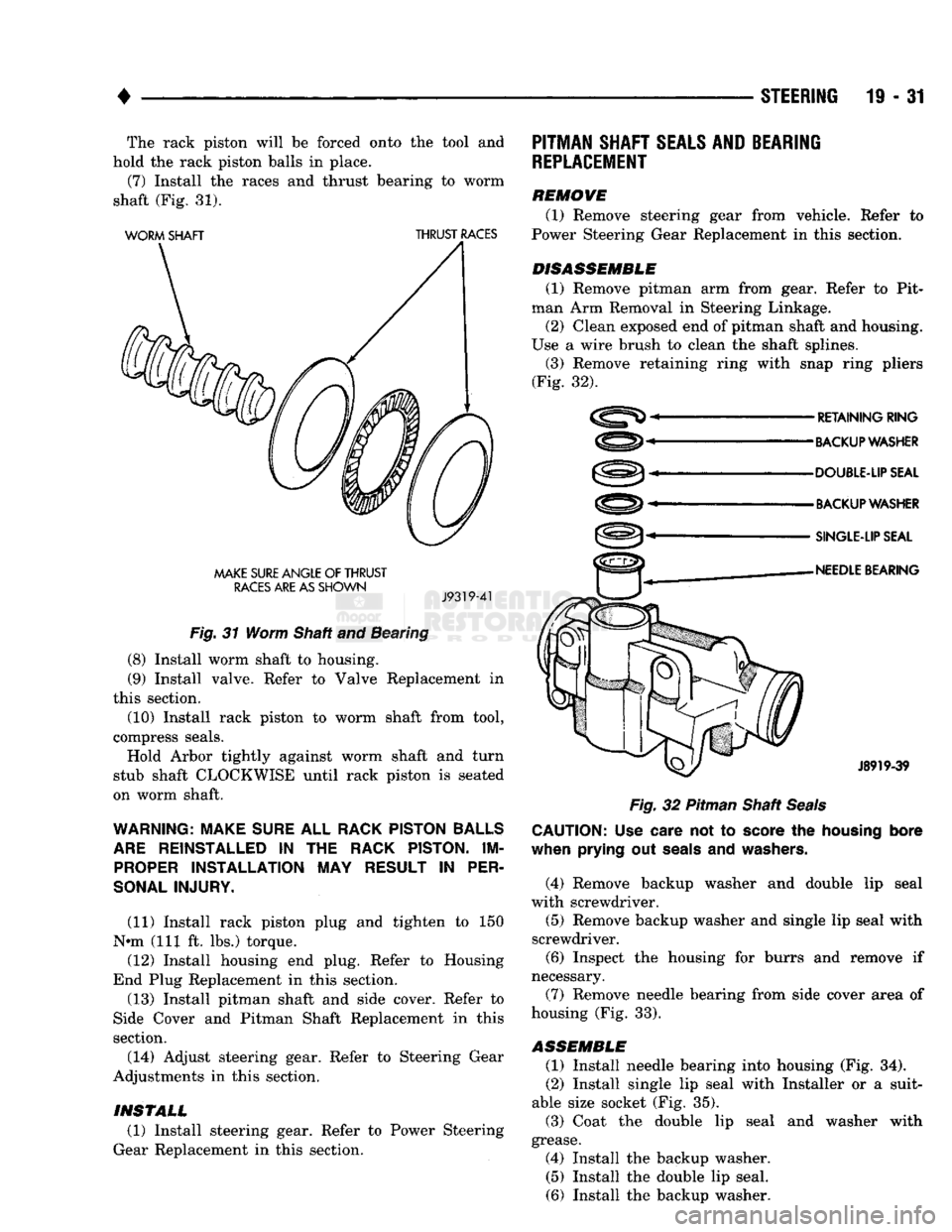
hold the rack piston balls in place. (7) Install the races and thrust bearing to worm
shaft (Fig. 31).
WORM
SHAFT
THRUST
RACES
MAKE
SURE
ANGLE
OF
THRUST
RACES
ARE AS
SHOWN
J9319-41
Fig.
31 Worm Shaft and Bearing
(8) Install worm shaft to housing. (9) Install valve. Refer to Valve Replacement in
this section.
(10) Install rack piston to worm shaft from tool,
compress seals. Hold Arbor tightly against worm shaft and turn
stub shaft CLOCKWISE until rack piston is seated
on worm shaft.
WARNING: MAKE
SURE
ALL
RACK PISTON BALLS
ARE
REINSTALLED
IN THE
RACK PISTON.
IM
PROPER
INSTALLATION
MAY
RESULT
IN
PER
SONAL INJURY.
(11) Install rack piston plug and tighten to 150
N»m (111 ft. lbs.) torque. (12) Install housing end plug. Refer to Housing
End Plug Replacement in this section. (13) Install pitman shaft and side cover. Refer to
Side Cover and Pitman Shaft Replacement in this
section.
(14) Adjust steering gear. Refer to Steering Gear
Adjustments in this section.
PITMAN
SHAFT
SEALS AND
BEARING
REPLACEMENT
REMOVE (1) Remove steering gear from vehicle. Refer to
Power Steering Gear Replacement in this section.
DISASSEMBLE
(1) Remove pitman arm from gear. Refer to Pit
man Arm Removal in Steering Linkage.
(2) Clean exposed end of pitman shaft and housing.
Use a wire brush to clean the shaft splines. (3) Remove retaining ring with snap ring pliers
(Fig. 32).
RETAINING
RING
BACKUP WASHER
DOUBLE-UP SEAL
BACKUP WASHER
SINGLE-LIP SEAL
NEEDLE
BEARING
J8919-39
Fig.
32 Pitman Shaft
Seals
CAUTION:
Use
care
not to
score
the
housing
bore
when
prying
out
seals
and
washers.
(4) Remove backup washer and double lip seal
with screwdriver.
(5) Remove backup washer and single lip seal with
screwdriver. (6) Inspect the housing for burrs and remove if
necessary.
(7) Remove needle bearing from side cover area of
housing (Fig. 33).
ASSEMBLE
(1) Install needle bearing into housing (Fig. 34).
(2) Install single lip seal with Installer or a suit
able size socket (Fig. 35).
(3) Coat the double lip seal and washer with
grease. (4) Install the backup washer. (5) Install the double lip seal.
(6) Install the backup washer.
INSTALL
(1) Install steering gear. Refer to Power Steering
Gear Replacement in this section.
Page 997 of 1502
19-36 STEERING
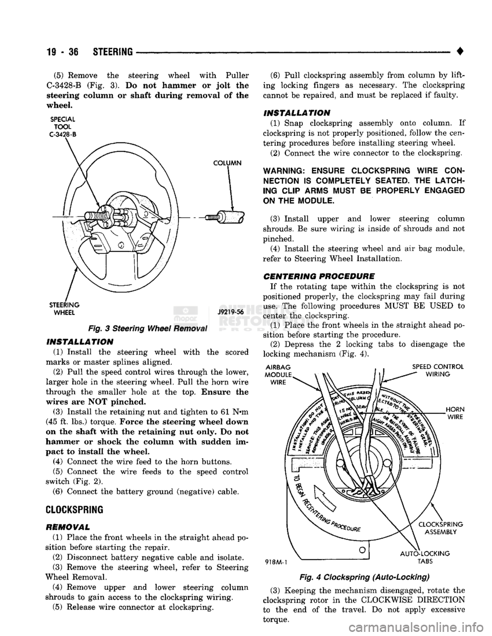
• (5) Remove the steering wheel with Puller
C-3428-B (Fig. 3). Do not hammer or jolt the
steering column or shaft during removal of the
wheel.
SPECIAL TOOL
C-3428-B
STEERING WHEEL J9219-56
Fig.
3 Steering
Wheel
Removal
INSTALLATION
(1) Install the steering wheel with the scored
marks or master splines aligned. (2) Pull the speed control wires through the lower,
larger hole in the steering wheel. Pull the horn wire
through the smaller hole at the top. Ensure the
wires are NOT pinched.
(3) Install the retaining nut and tighten to 61 N«m
(45 ft. lbs.) torque. Force the steering wheel down
on the shaft with the retaining nut only. Do not
hammer or shock the column with sudden im
pact to install the wheel.
(4) Connect the wire feed to the horn buttons.
(5) Connect the wire feeds to the speed control
switch (Fig. 2).
(6) Connect the battery ground (negative) cable.
CLOCKSPRING
REMOVAL
(1) Place the front wheels in the straight ahead po
sition before starting the repair.
(2) Disconnect battery negative cable and isolate.
(3) Remove the steering wheel, refer to Steering
Wheel Removal. (4) Remove upper and lower steering column
shrouds to gain access to the clockspring wiring.
(5) Release wire connector at clockspring. (6) Pull clockspring assembly from column by lift
ing locking fingers as necessary. The clockspring
cannot be repaired, and must be replaced if faulty.
INSTALLATION
(1) Snap clockspring assembly onto column. If
clockspring is not properly positioned, follow the cen
tering procedures before installing steering wheel.
(2) Connect the wire connector to the clockspring.
WARNING: ENSURE CLOCKSPRING WIRE CON NECTION
IS
COMPLETELY SEATED.
THE
LATCH
ING CLIP ARMS MUST
BE
PROPERLY ENGAGED
ON
THE
MODULE.
(3) Install upper and lower steering column
shrouds. Be sure wiring is inside of shrouds and not
pinched. (4) Install the steering wheel and air bag module,
refer to Steering Wheel Installation.
CENTERING
PROCEDURE
If the rotating tape within the clockspring is not
positioned properly, the clockspring may fail during
use.
The following procedures MUST BE USED to
center the clockspring.
(1) Place the front wheels in the straight ahead po
sition before starting the procedure. (2) Depress the 2 locking tabs to disengage the
locking mechanism (Fig. 4).
Fig.
4
Clockspring
(Auto-Locking)
(3) Keeping the mechanism disengaged, rotate the
clockspring rotor in the CLOCKWISE DIRECTION
to the end of the travel. Do not apply excessive
torque.