1993 DODGE TRUCK clock
[x] Cancel search: clockPage 998 of 1502
•
STEERING
19 • 37 (4) From the end of travel, rotate the rotor 2 1/2
full turns in the COUNTER CLOCKWISE direction.
The horn wire should end up at the top and the squib
wire at the bottom (Fig. 4).
(5) Install the steering wheel, refer to Steering
Wheel Installation.
COLUMN—
REMOVAL/INSTALLATION
CAUTION:
Bumping,
jolting
and
hammering
on the
steering
column
shaft
and
gear
shift
tube
must
be
avoided
during
all
service
procedures.
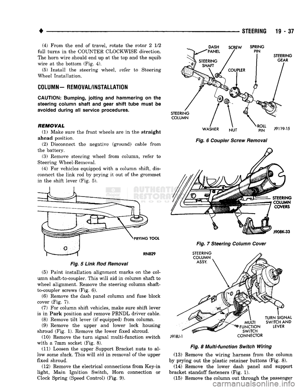
REMOVAL (1) Make sure the front wheels are in the straight
ahead position.
(2) Disconnect the negative (ground) cable from
the battery.
(3) Remove steering wheel from column, refer to
Steering Wheel-Removal.
(4) For vehicles equipped with a column shift, dis
connect the link rod by prying it out of the grommet in the shift lever (Fig. 5).
DASH
"PANEL SCREW
SPRING
PIN
PRYING
TOOL
RN829
Fig.
5
Link
Rod
Removal
(5) Paint installation alignment marks on the col
umn shaft-to-coupler. This will aid in column shaft to
wheel alignment. Remove the steering column shaft-
to-coupler screws (Fig. 6).
(6) Remove the dash panel column and fuse block
cover (Fig. 7).
(7) For column shift vehicles, make sure shift lever
is in Park position and remove PRNDL driver cable.
(8) Remove tilt lever (if equipped) from column.
(9) Remove the upper and lower lock housing
shroud (Fig. 1). Remove the lower fixed shroud.
(10) Remove the turn signal multi-function switch
with a 7mm socket (Fig. 8). (11) Loosen the upper Support Bracket nuts to al
low some slack. This will aid in removal of the upper
fixed shroud.
(12) Remove the electrical connections from Key-in
light, Main Ignition Switch, Horn connection or
Clock
Spring (Speed
Control)
(Fig. 9).
STEERING
GEAR
STEERING COLUMN
WASHER NUT
RJ?N"
J9119-15
Fig.
6
Coupler
Screw
Removal
STEERING COLUMN COVERS
J908K-33
Fig.
7 Steering
Column
Cover
STEERING COLUMN
ASSY.
J918J-1
MULTI
^FUNCTION
SWITCH
CONNECTOR
TURN
SIGNAL
SWITCH
AND
LEVER
Fig.
8 Multi-function
Switch
Wiring (13) Remove the wiring harness from the column
by prying out the plastic retainer buttons (Fig. 8).
(14) Remove the lower dash panel and support
bracket standoff fasteners (Fig. 1). (15) Remove the column out through the passenger
Page 1009 of 1502
21
- 8
NV4500
TRANSMISSION OVERHAUL
———— ^ ____ - #
CLUTCH
GEAR J9221-89
Fig. 9 Removing Countershaft Fifth Speed Clutch Gear Snap Ring
FIFTH GEAR
SHIFT FORK
J9221-94
Fig. 10 Removing Fifth Gear Shift Fork Roil Pins
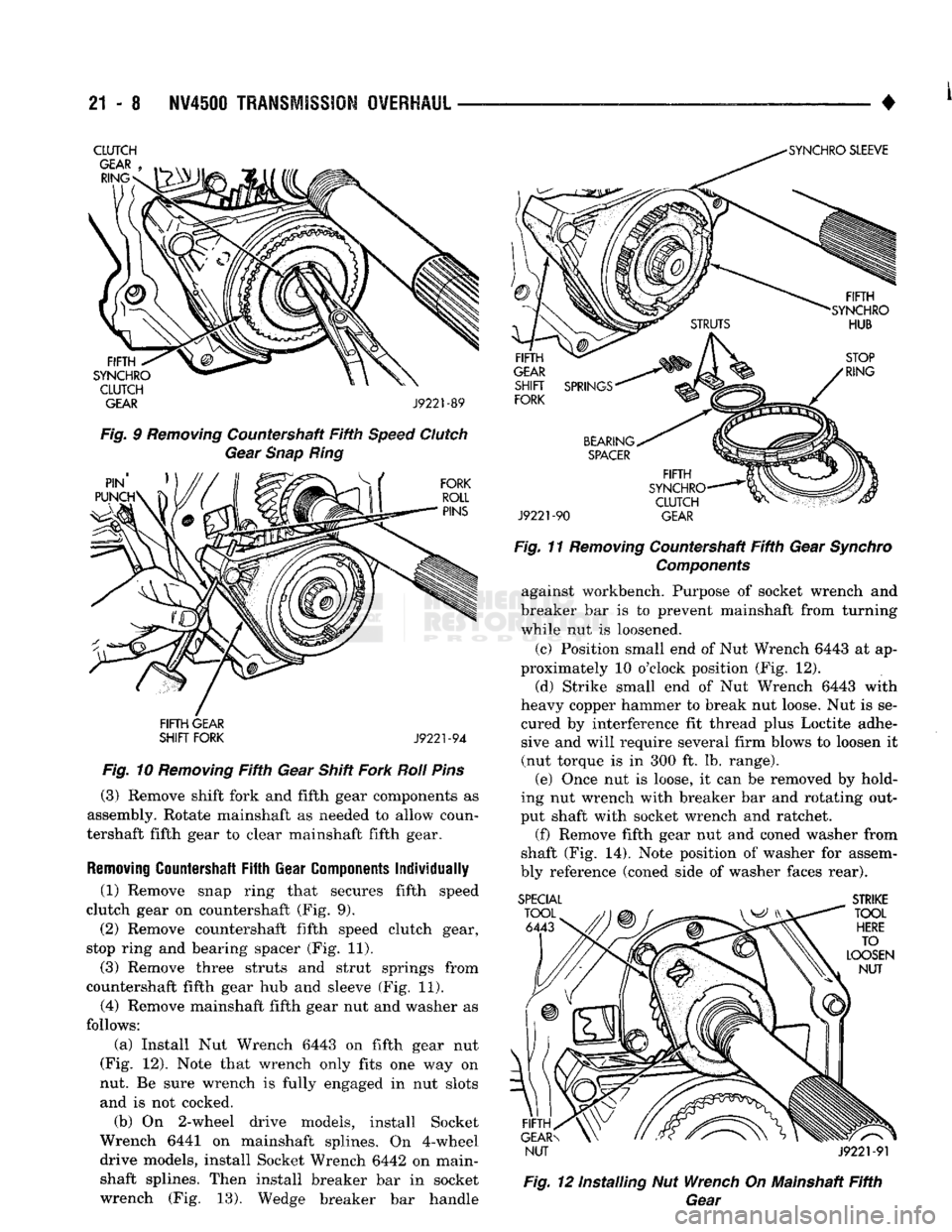
(3) Remove shift fork and fifth gear components as
assembly. Rotate mainshaft as needed to allow coun
tershaft fifth gear to clear mainshaft fifth gear.
Removing
Countershaft
Fifth
Gear
Components
Individually
(1) Remove snap ring that secures fifth speed
clutch gear on countershaft (Fig. 9). (2) Remove countershaft fifth speed clutch gear,
stop ring and bearing spacer (Fig. 11).
(3) Remove three struts and strut springs from
countershaft fifth gear hub and sleeve (Fig. 11). (4) Remove mainshaft fifth gear nut and washer as
follows:
(a) Install Nut Wrench 6443 on fifth gear nut
(Fig. 12). Note that wrench only fits one way on
nut. Be sure wrench is fully engaged in nut slots and is not cocked.
(b) On 2-wheel drive models, install Socket
Wrench 6441 on mainshaft splines. On 4-wheel drive models, install Socket Wrench 6442 on main-
shaft splines. Then install breaker bar in socket wrench (Fig. 13). Wedge breaker bar handle
J9221-90
GEAR
Fig. 11 Removing Countershaft Fifth Gear Synchro Components against workbench. Purpose of socket wrench and
breaker bar is to prevent mainshaft from turning
while nut is loosened.
(c) Position small end of Nut Wrench 6443 at ap
proximately 10 o'clock position (Fig. 12).
(d) Strike small end of Nut Wrench 6443 with
heavy copper hammer to break nut loose. Nut is se
cured by interference fit thread plus Loctite adhe sive and will require several firm blows to loosen it
(nut torque is in 300 ft. lb. range). (e) Once nut is loose, it can be removed by hold
ing nut wrench with breaker bar and rotating out
put shaft with socket wrench and ratchet.
(f)
Remove fifth gear nut and coned washer from
shaft (Fig. 14). Note position of washer for assem
bly reference (coned side of washer faces rear). SPECIAL
STRIKE
NUT J9221-91
Fig. 12 installing Nut Wrench On Mainshaft Fifth Gear
Page 1014 of 1502
+
MAINSHAFT AND GEARTRAIN REMOVAL
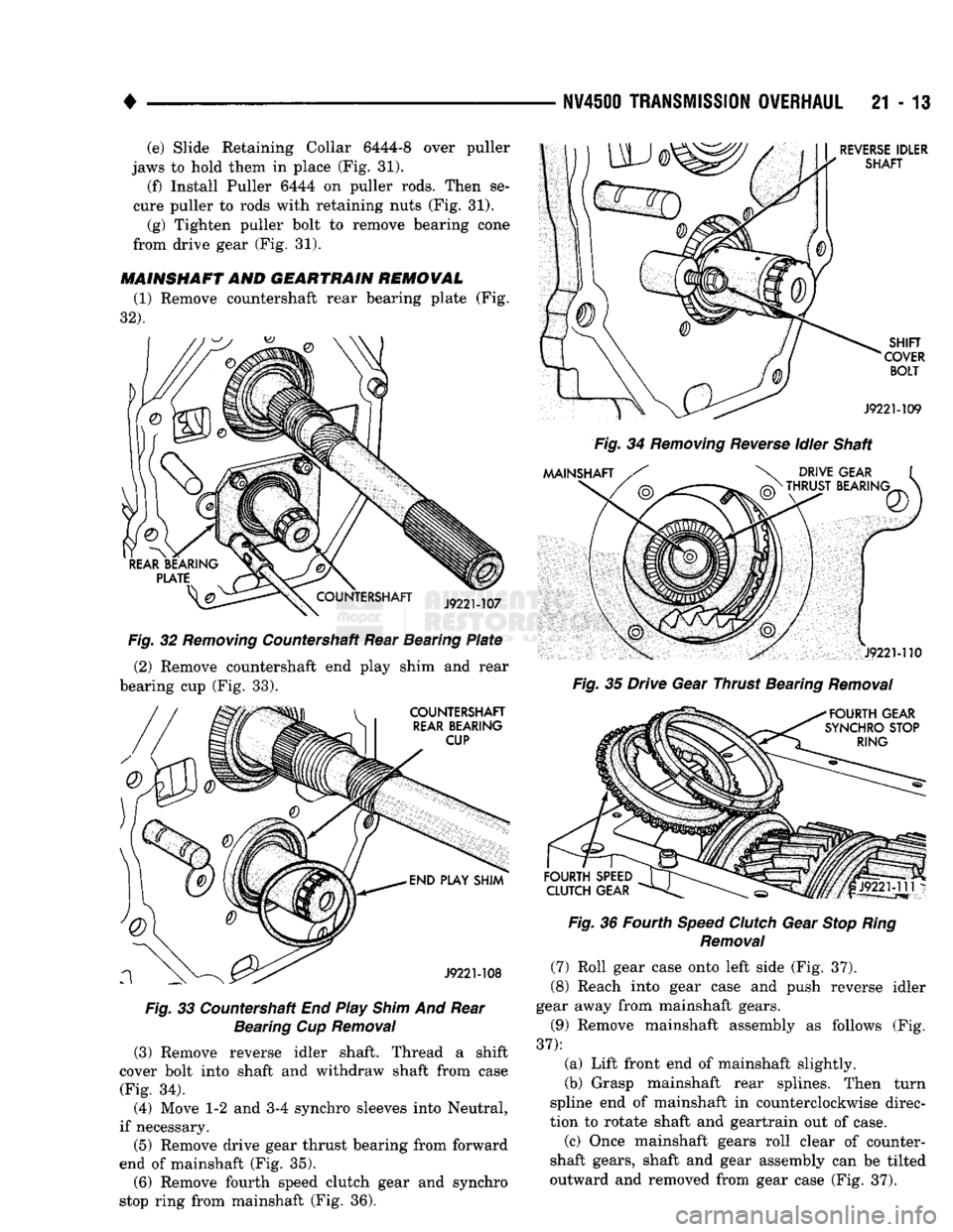
(1) Remove countershaft rear bearing plate (Fig.
32).
Fig.
32
Removing
Countershaft Rear Bearing
Plate
(2) Remove countershaft end play shim and rear
bearing cup (Fig. 33).
Fig.
33 Countershaft End Play
Shim
And Rear
Bearing
Cup
Removal
(3) Remove reverse idler shaft. Thread a shift
cover bolt into shaft and withdraw shaft from case (Fig. 34).
(4) Move 1-2 and 3-4 synchro sleeves into Neutral,
if necessary.
(5)
Remove drive gear thrust bearing from forward
end of mainshaft (Fig. 35).
(6) Remove fourth speed clutch gear and synchro
stop ring from mainshaft (Fig. 36).
N¥4S0O
TRANSMISSION
OVERHAUL
21 - 13
Fig.
34
Removing
Reverse
Idler Shaft
Fig.
35 Drive Gear Thrust Bearing
Removal
Fig.
36 Fourth
Speed
Clutch
Gear
Stop
Ring
Removal
(7) Roll gear case onto left side (Fig. 37).
(8) Reach into gear case and push reverse idler
gear away from mainshaft gears.
(9) Remove mainshaft assembly as follows (Fig.
37):
(a) Lift front end of mainshaft slightly.
(b) Grasp mainshaft rear splines. Then turn
spline end of mainshaft in counterclockwise direc
tion to rotate shaft and geartrain out of case.
(c) Once mainshaft gears roll clear of counter
shaft gears, shaft and gear assembly can be tilted
outward and removed from gear case (Fig. 37).
(e) Slide Retaining Collar 6444-8 over puller
jaws to hold them in place (Fig. 31).
(f) Install Puller 6444 on puller rods. Then se
cure puller to rods with retaining nuts (Fig. 31).
(g) Tighten puller bolt to remove bearing cone
from drive gear (Fig. 31).
Page 1030 of 1502
•
NV4600 TRANSMISSION OVERHAUL
21 - 29
COUNTERSHAFT
REAR
BEARING
PLATE
IDLER
SHAFT
J9221-168
Fig.
96 Countershaft Rear Bearing
Plate
installation
DIAL
INDICATOR
INDICATOR
MOUNTING
ARM
AND
BASE
J922M69 Fig.
97
Measuring
Countershaft End Play
REAR
BEARING
CUP
END
PLAY
SHIM
(SELECTIVE) Fig.
98 Installing Countershaft End Play
Shim
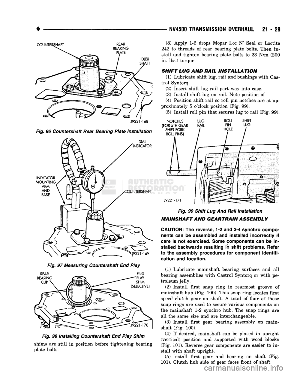
shims are still in position before tightening bearing
plate bolts. (8) Apply 1-2 drops Mopar Loc N' Seal or Loctite
242 to threads of rear bearing plate bolts. Then in
stall and tighten bearing plate bolts to 23 Nnn (200
in. lbs.) torque.
SHIFT
LUG AND
RAIL
INSTALLATION
(1) Lubricate shift lug, rail and bushings with Cas-
trol Syntorq. (2) Insert shift lug rail part way into case.
(3) Install shift lug on rail. Note position of
(4) Position shift rail so roll pin notches are at ap
proximately 5 o'clock position (Fig. 99).
(5) Install roll pin that secures lug to rail (Fig. 99).
NOTCHES
(FOR 5TH GEAR SHIFT FORK ROLL PINS) LUG
RAIL
SHIFT
LUG
J922M71 Fig.
99 Shift Lug And Rail
Installation
MAINSHAFT
AND
GEARTRAIN ASSEMBLY
CAUTION:
The
reverse,
1-2 and 3-4
synchro compo nents
can be
assembled
and
installed incorrectly
if
care
is not
exercised. Some components
can be in
stalled backwards resulting
in
shift problems. Refer
to
the
assembly procedures
for
component
identifi
cation
and
location.
(1) Lubricate mainshaft bearing surfaces and all
bearing assemblies with Castrol Syntorq or with pe
troleum jelly.
(2) Install first snap ring in rearmost groove of
mainshaft hub (Fig. 100). This snap ring locates first speed clutch gear on shaft. A total of four of these
snap rings are used to secure various components on
the mainshaft 1-2 synchro hub. The snap rings are all the same size and are interchangeable.
(3) Install first gear bearing assembly on main-
shaft (Fig. 100).
(4) If desired, mainshaft can be placed in upright
(vertical) position and supported with wood blocks
(Fig. 101). Reverse gear components are easier to in
stall with shaft upright. (5) Install first gear and bearing on shaft (Fig.
101).
Clutch hub side of gear faces front of shaft.
Page 1039 of 1502
21
- 38
NV45U0
TRANSMISSION OVERHAUL
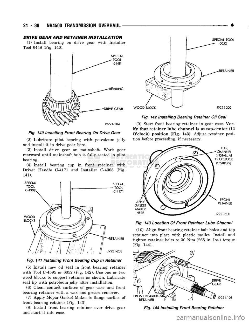
DRIVE GEAR AND RETAINER INSTALLATION
(1) Install bearing on drive gear with Installer
Tool 6448 (Fig. 140).
SPECIAL
-TOOL
6448
BEARING DRIVE GEAR
J9221-204
Fig.
140 installing Front Bearing On Drive Gear
(2) Lubricate pilot bearing with petroleum jelly
and install it in drive gear bore.
(3) Install drive gear on mainshaft. Work gear
rearward until mainshaft hub is fully seated in pilot
bearing.
(4) Install bearing cup in front retainer with
Driver Handle C-4171 and Installer C-4308 (Fig.
141).
SPECIAL
TOOL
C-4308
SPECIAL
TOOL
C-4171
WOOD
BLOCKS
RETAINER
J9221-203
Fig.
141 Installing Front Bearing Cup In Retainer
(5) Install new oil seal in front bearing retainer
with Tool C-4595 or 6052 (Fig. 142). Use one or two
wood blocks to support retainer as shown. Lubricate seal lip with petroleum jelly after installation.
(6) Clean contact surfaces of gear case and front
bearing retainer with a wax and grease remover. (7) Apply Mopar Gasket Maker to flange surface of
front bearing retainer (Fig. 143). (8) Install front bearing retainer over drive gear
and start it into case.
WOOD
BLOCK
SPECIAL
TOOL
6052
RETAINER
J9221-202
Fig.
142 Installing Bearing Retainer Oil
Seal
(9) Start front bearing retainer in gear case. Ver
ify that retainer lube channel is at top-center (12
O'clock)
position (Fig. 143). Adjust retainer posi
tion before proceeding, if necessary.
LUBE
CHANNEL
(INSTALL
AT
12
O'CLOCK
POSITION)
APPLY
GASKET
MAKER
HERE
FRONT
RETAINER
J9221-231
Fig.
143 Location Of Front Retainer
Lube
Channel
(10) Align front bearing retainer bolt holes and tap
retainer into place with plastic mallet. Install and
tighten retainer bolts to 30 N-m (265 in. lbs.) torque (Fig. 144).
FRONT
BEARING
RETAINER
9 J9221-103
Fig.
144 Installing Front Bearing Retainer
Page 1045 of 1502
21
- 44
NV450Q
TRANSMISSION
OVERHAUL
REVERSE
INHIBITOR
J9221-255
Fig.
165
Reverse
Inhibitor
Mounting
HOSE
VENT
VALVE
VENT
TUBE
CLAMP
J9221-256
Fig.
166 Shift
Cover
Vent
Components
Backup
Light
Switch
Replacement
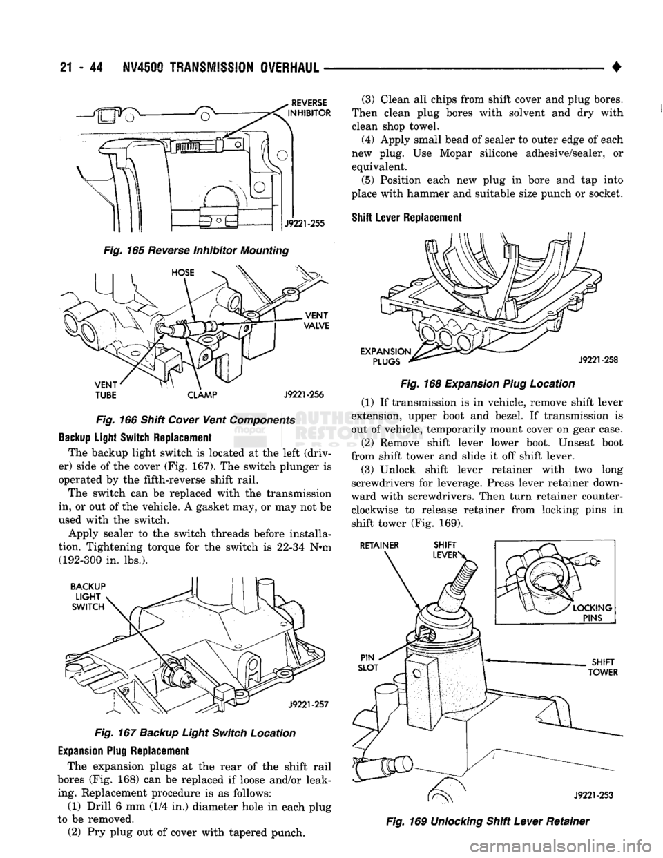
The backup light switch is located at the left (driv
er) side of the cover (Fig. 167). The switch plunger is
operated by the fifth-reverse shift rail.
The switch can be replaced with the transmission
in, or out of the vehicle. A gasket may, or may not be
used with the switch.
Apply sealer to the switch threads before installa
tion. Tightening torque for the switch is 22-34 N#m (192-300 in. lbs.).
BACKUP
LIGHT
SWITCH
J9221-257
Fig.
167
Backup
Light
Switch
Location
Expansion Plug
Replacement
The expansion plugs at the rear of the shift rail
bores (Fig. 168) can be replaced if loose and/or leak ing. Replacement procedure is as follows:
(1) Drill 6 mm (1/4 in.) diameter hole in each plug
to be removed.
(2) Pry plug out of cover with tapered punch. (3) Clean all chips from shift cover and plug bores.
Then clean plug bores with solvent and dry with
clean shop towel. (4) Apply small bead of sealer to outer edge of each
new plug. Use Mopar silicone adhesive/sealer, or
equivalent.
(5) Position each new plug in bore and tap into
place with hammer and suitable size punch or socket.
Shift
Lever
Replacement
EXPANSION
PLUGS
J9221-258
Fig.
168
Expansion
Plug
Location (1) If transmission is in vehicle, remove shift lever
extension, upper boot and bezel. If transmission is
out of vehicle, temporarily mount cover on gear case.
(2) Remove shift lever lower boot. Unseat boot
from shift tower and slide it off shift lever. (3) Unlock shift lever retainer with two long
screwdrivers for leverage. Press lever retainer down
ward with screwdrivers. Then turn retainer counter clockwise to release retainer from locking pins in shift tower (Fig. 169).
RETAINER
Iff^r
J9221-253
Fig.
169
Unlocking
Shift
Lever
Retainer
Page 1135 of 1502
21
- 134
IN-WEHiCLE SER¥iCE-32RH/3IRH/37RH/42RH/46RH
• • On 36RH/37RH746RH, back off adjusting screw
two turns. (6) Hold adjusting screw in place with backup
wrench. Then tighten locknut to 34 N*m (25 ft. lbs.) torque.
(7) Position new gasket on oil pan and install pan
on transmission. Tighten pan bolts to 17 N»m (13 ft.
lbs.) torque.
(8) Lower vehicle and refill transmission with Mo
par ATF Plus, type 7176, or Dexron II™ fluid.
Fig. § Rear Band Adjustment Screw Location
SPEEDOMETER
SERVICE
Rear axle gear ratio and tire size determine speed
ometer pinion requirements. If the gear must be re
placed, refer to the parts catalogue information for
the correct pinion.
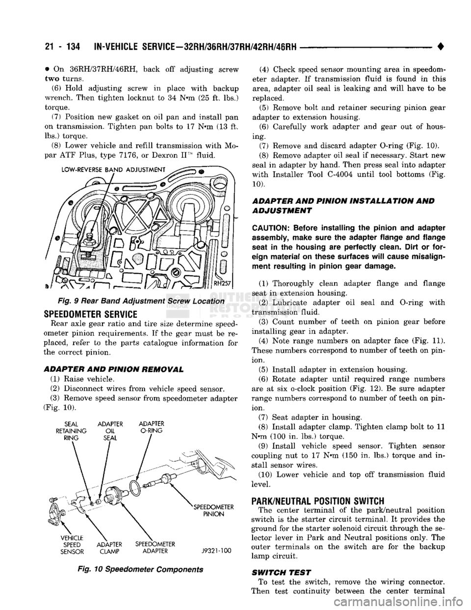
ADAPTER
AND
PINION REMOWAL
(1) Raise vehicle.
(2) Disconnect wires from vehicle speed sensor.
(3) Remove speed sensor from speedometer adapter
(Fig. 10). SEAL ADAPTER ADAPTER
RETAINING OIL O-RING
SPEED ADAPTER SPEEDOMETER
SENSOR CLAMP ADAPTER J932M00
Fig. 10 Speedometer Components (4) Check speed sensor mounting area in speedom
eter adapter. If transmission fluid is found in this area, adapter oil seal is leaking and will have to be
replaced. (5) Remove bolt and retainer securing pinion gear
adapter to extension housing. (6) Carefully work adapter and gear out of hous
ing. (7) Remove and discard adapter O-ring (Fig. 10).
(8) Remove adapter oil seal if necessary. Start new
seal in adapter by hand. Then press seal into adapter
with Installer Tool C-4004 until tool bottoms (Fig.
10).
ADAPTER AND PINION INSTALLATION AND
ADJUSTMENT
CAUTION:
Before installing
the
pinion
and
adapter
assembly,
make sure
the
adapter flange
and
flange
seat
in the
housing
are
perfectly clean. Dirt
or
for
eign
material
on
these surfaces
will
cause misalign ment resulting
in
pinion gear damage.
(1) Thoroughly clean adapter flange and flange
seat in extension housing.
(2) Lubricate adapter oil seal and O-ring with
transmission fluid.
(3) Count number of teeth on pinion gear before
installing gear in adapter.
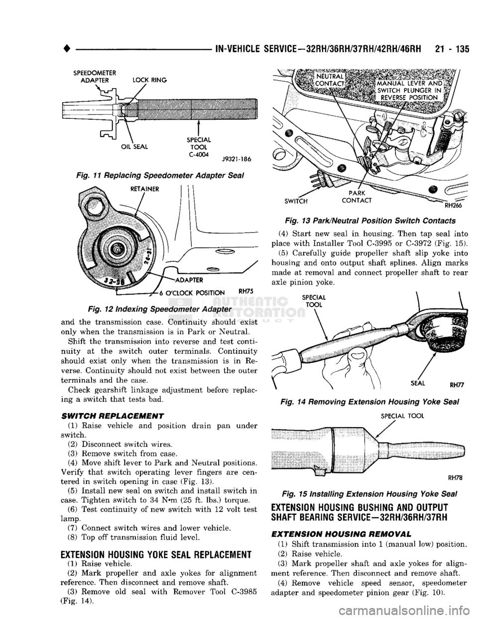
(4) Note range numbers on adapter face (Fig. 11).
These numbers correspond to number of teeth on pin ion.
(5) Install adapter in extension housing.
(6) Rotate adapter until required range numbers
are at six o-clock position (Fig. 12). Be sure adapter
range numbers correspond to number of teeth on pin ion.
(7) Seat adapter in housing.
(8) Install adapter clamp. Tighten clamp bolt to 11
N*m (100 in. lbs.) torque.
(9) Install vehicle speed sensor. Tighten sensor
coupling nut to 17 N*m (150 in. lbs.) torque and in
stall sensor wires.
(10) Lower vehicle and top off transmission fluid
level.
PARK/NEUTRAL
POSITION SWJTCH
The center terminal of the park/neutral position
switch is the starter circuit terminal. It provides the
ground for the starter solenoid circuit through the se
lector lever in Park and Neutral positions only. The
outer terminals on the switch are for the backup
lamp circuit.
SWITCH TEST To test the switch, remove the wiring connector.
Then test continuity between the center terminal
Page 1136 of 1502
•
IN-VEHICLE
SERVICE-32RH/3eRH/37RH/42RH/46RH
21 - 135
SPEEDOMETER
ADAPTER
LOCK
RING
OIL
SEAL
SPECIAL
TOOL
C-4004
J9321-186
Fig. 11 Replacing Speedometer Adapter Seal
RETAINER
-ADAPTER
-7^6
O'CLOCK
POSITION
RH75
Fig.
12 Indexing Speedometer Adapter
and the transmission case. Continuity should exist
only when the transmission is in Park or Neutral.
Shift the transmission into reverse and test conti
nuity at the switch outer terminals. Continuity should exist only when the transmission is in Re
verse. Continuity should not exist between the outer
terminals and the case.
Check gearshift linkage adjustment before replac
ing a switch that tests bad.
SWITCH
REPLACEMENT
(1) Raise vehicle and position drain pan under
switch. (2) Disconnect switch wires.
(3) Remove switch from case.
(4) Move shift lever to Park and Neutral positions.
Verify that switch operating lever fingers are cen
tered in switch opening in case (Fig. 13).
(5) Install new seal on switch and install switch in
case.
Tighten switch to 34 Nnn (25 ft. lbs.) torque. (6) Test continuity of new switch with 12 volt test
lamp.
(7) Connect switch wires and lower vehicle.
(8) Top off transmission fluid level.
EXTENSION HOUSING
YOKE
SEAL REPLACEMENT (1) Raise vehicle.
(2) Mark propeller and axle yokes for alignment
reference. Then disconnect and remove shaft. (3) Remove old seal with Remover Tool C-3985
(Fig. 14).
SWITCH
RH266
Fig.
13 Park/Neutral Position
Switch
Contacts (4) Start new seal in housing. Then tap seal into
place with Installer Tool
C-3995
or
C-3972
(Fig. 15).
(5)
Carefully guide propeller shaft slip yoke into
housing and onto output shaft splines. Align marks made at removal and connect propeller shaft to rear
axle pinion yoke.
SPECIAL
TOOL
Fig.
14
Removing
Extension
Housing
Yoke
Seal
SPECIAL
TOOL
RH78
Fig.
15 Installing Extension
Housing
Yoke
Seal
EXTENSION HOUSING BUSHING AND OUTPUT
SHAFT BEARING
SERVlCE-32RH/3eRH/37RH
EXTENSION
HOUSING
REMOVAL
(1) Shift transmission into 1 (manual low) position.
(2) Raise vehicle.
(3) Mark propeller shaft and axle yokes for align
ment reference. Then disconnect and remove shaft. (4) Remove vehicle speed sensor, speedometer
adapter and speedometer pinion gear (Fig. 10).