1993 DODGE TRUCK park assist
[x] Cancel search: park assistPage 28 of 1502
•
LUBRICATION AND MAINTENANCE
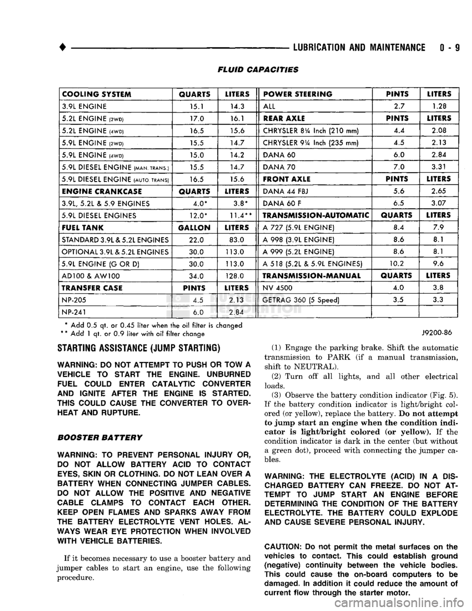
0 - 9 FLUID CAPACITIES
COOLING SYSTEM
QUARTS
LITERS
POWER STEERING PINTS
LITERS
3.9L ENGINE 15.1 14.3
ALL
2.7
1.28
5.2L ENGINE
(2WD)
17.0 16.1
REAR
AXLE
PINTS
LITERS
5.2L ENGINE
(4WD)
16.5 15.6
CHRYSLER
BVa
Inch
(210
mm) 4.4
2.08
5.9L ENGINE
(2WD)
15.5 14.7
CHRYSLER
9Va
Inch
(235
mm) 4.5
2.13
5.9L ENGINE
(4WD)
15.0 14.2
DANA
60 6.0
2.84
5.9L DIESEL ENGINE (MAN.TRANS.) 15.5 14.7
DANA
70 7.0
3.31
5.9L DIESEL ENGINE
(AUTO,
TRANS)
16.5 15.6
FRONT AXLE
PINTS
LITERS
ENGINE
CRANKCASE
QUARTS
LITERS
DANA
44
FBJ 5.6
2.65
3.9L,
5.2L & 5.9
ENGINES 4.0* 3.8*
DANA
60 F
6.5
3.07
5.9L DIESEL ENGINES 12.0*
11.4**
TRANSMISSION-AUTOMATIC
QUARTS
LITERS
FUEL TANK GALLON
LITERS
A
727 (5.9L
ENGINE) 8.4
7.9
STANDARD
3.9L & 5.2L ENGINES 22.0 83.0
A
998 (3.9L
ENGINE) 8.6
8.1
OPTIONAL 3.9L & 5.2L ENGINES 30.0 113.0
A
999 (5.2L
ENGINE) 8.6
8.1
5.9L ENGINE
{G
OR
D)
30.0 113.0
A
518 (5.2L & 5.9L
ENGINES) 10.2
9.6
AD 100
&
AW 100 34.0 128.0
TRANSMISSION-MANUAL
QUARTS
LITERS
TRANSFER
CASE
PINTS
LITERS
NV
4500
4.0
3.8
NP-205
4.5 2.13
GETRAG
360 (5
Speed)
3.5
3.3
NP-241
6.0
2.84
* Add
0.5 qt. or 0.45
liter
when
the oil filter
is
changed
*
*
Add
1 qt. or 0.9
liter
with
oil filter
change STARTING ASSISTANCE (JUMP STARTING)
WARNING:
DO NOT
ATTEMPT
TO
PUSH
OR
TOW
A
VEHICLE
TO
START
THE
ENGINE. UNBURNED FUEL COULD ENTER CATALYTIC CONVERTER
AND IGNITE AFTER
THE
ENGINE
IS
STARTED.
THIS COULD CAUSE
THE
CONVERTER
TO
OVER HEAT AND RUPTURE.
BOOSTER BATTERY
WARNING:
TO
PREVENT PERSONAL INJURY
OR,
DO
NOT
ALLOW BATTERY ACID
TO
CONTACT
EYES,
SKIN
OR
CLOTHING.
DO NOT
LEAN OVER
A
BATTERY WHEN CONNECTING JUMPER
CABLES.
DO
NOT
ALLOW
THE
POSITIVE
AND
NEGATIVE
CABLE
CLAMPS
TO
CONTACT EACH OTHER.
KEEP
OPEN FLAMES
AND
SPARKS
AWAY FROM
THE BATTERY ELECTROLYTE VENT HOLES.
AL
WAYS
WEAR
EYE
PROTECTION WHEN INVOLVED
WITH
VEHICLE BATTERIES.
If it becomes necessary to use a booster battery and
jumper cables to start an engine, use the following procedure.
J9200-86
(1) Engage the parking brake. Shift the automatic
transmission to PARK (if a manual transmission, shift to NEUTRAL).
(2) Turn off all lights, and all other electrical
loads.
(3)
Observe the battery condition indicator (Fig. 5).
If the battery condition indicator is light/bright col
ored (or yellow), replace the battery. Do not attempt
to jump start an engine when the condition indi
cator is light/bright colored (or yellow). If the
condition indicator is dark in the center (but without a green dot), proceed with connecting the jumper ca
bles.
WARNING:
THE
ELECTROLYTE (ACID)
IN A
DIS
CHARGED
BATTERY
CAN
FREEZE.
DO NOT AT
TEMPT
TO
JUMP START
AN
ENGINE BEFORE DETERMINING
THE
CONDITION
OF THE
BATTERY
ELECTROLYTE.
THE
BATTERY COULD EXPLODE
AND CAUSE SEVERE PERSONAL INJURY.
CAUTION:
Do not
permit
the
metal
surfaces
on the
vehicles
to
contact.
This
could
establish
ground
(negative)
continuity
between
the
vehicle
bodies.
This
could
cause
the
on-board
computers
to be
damaged.
In
addition
it
could
reduce
the
amount
of
current
flow
through
the
starter
motor.
Page 188 of 1502
•
BRAKES
BRAKES
5 - 1
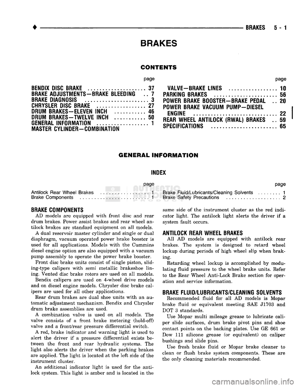
CONTENTS
page
BENDIX
DISC
BRAKE
37
BRAKE
ADJUSTMENTS-BRAKE BLEEDING .. 7
BRAKE
DIAGNOSIS
3
CHRYSLER
DISC
BRAKE
27
DRUM
BRAKES-ELEVEN
INCH 46
DRUM
BRAKES-TWELVE
INCH 50
GENERAL
INFORMATION 1
MASTER
CYLINDER-COMBINATION
page
VALVE-BRAKE
LINES 10
PARKING
BRAKES
56
POWER
BRAKE
BOOSTER-BRAKE
PEDAL .. 20
POWER
BRAKE
VACUUM PUMP-DIESEL
ENGINE
...22
REAR
WHEEL ANTILOCK (RWAL)
BRAKES
.. 59
SPECIFICATIONS
65
GENERAL INFORMATION
INDEX
page
Antilock
Rear
Wheel
Brakes
1
Brake
Components 1
BRAKE
COMPONENTS
AD models are equipped with front disc and rear
drum brakes. Power assist brakes and rear wheel an
tilock brakes are standard equipment on all models. A dual reservoir master cylinder and single or dual
diaphragm, vacuum operated power brake booster is
used for all applications. Models with the Cummins
diesel engine option are also equipped with a vacuum
pump assembly to operate the power brake booster. Front disc brake units consist of single piston, slid-
ing-type calipers with semi metallic brakeshoe lin ing. Vented disc brake rotors are used on all models. Bendix calipers are used on 4-wheel drive models
and on diesel engine models. Chrysler disc brake cal
ipers are used for all other applications. Rear drum brakes are dual shoe units with an au
tomatic adjustment mechanism. Bendix and Chrysler drum brake assemblies are used. A combination valve is used on all models. The
valve consists of a front brake metering (hold-off)
valve and a front/rear pressure differential switch. A red, brake indicator and warning light is used to
alert the driver if a pressure differential exists be
tween the front and rear hydraulic systems. The light also alerts the driver when the parking brakes
are applied. The light is located at the left side of the
instrument cluster. An additional indicator light is used for the anti-
lock system. This light is amber and is located in the
page
Brake
Fluid/Lubricants/Cleaning
Solvents
1
Brake
Safety Precautions 2
same side of the instrument cluster as the red indi
cator light. The antilock light alerts the driver if a system fault occurs.
ANTILOCK
REAR
WHEEL
BRAKES
All AD models are equipped with antilock rear
brakes. The system is designed to retard wheel lockup during periods of high wheel slip when brak
ing. Retarding wheel lockup is accomplished by modu
lating fluid pressure to the wheel brake units. Refer
to the Rear Wheel Anti-Lock Brake section for oper ation and service information.
BRAKE
FLUID/LUBRICANTS/CLEANING SOLVENTS Recommended fluid for all AD models is Mopar
brake fluid or equivalent meeting SAE J1703 and DOT 3 standards. Use Mopar multi mileage grease to lubricate cali
per slide surfaces, drum brake pivot pins and shoe contact points on the backing plates. Use GE 661 or
Dow 111 silicone grease (or equivalent) on caliper
bushings and slide pins. Use fresh brake fluid or Mopar brake cleaner to
clean or flush brake system components. These are
the only cleaning materials recommended.
Page 327 of 1502
8A
- 6
ELECTRICAL
•
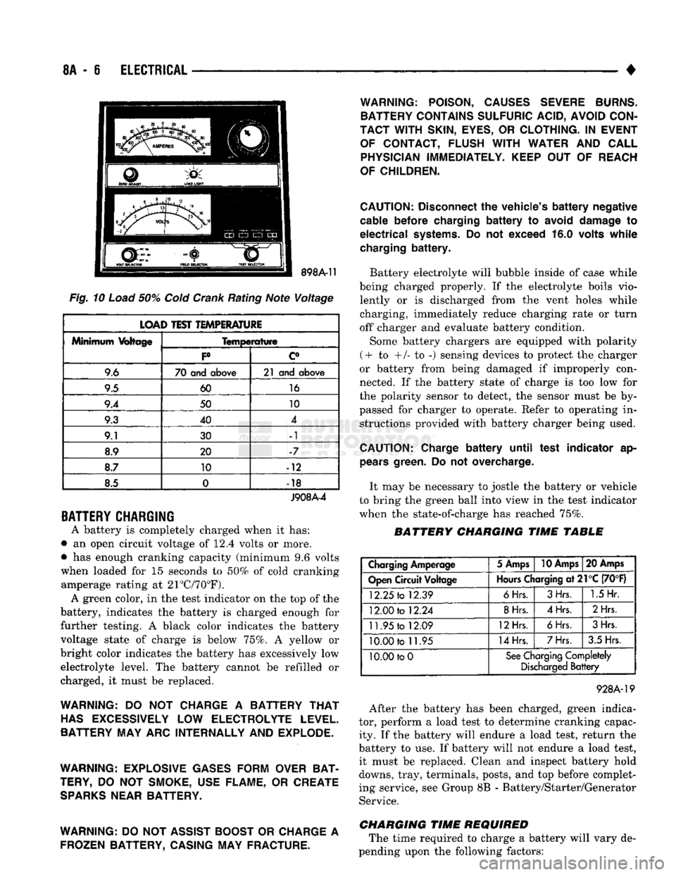
Fig.
10
Load
50%
Cold
Crank
Rating Note Voltage
LOAD TEST TEMPERATURE
Minimum
Voltage
Temperature
Minimum
Voltage
P c°
9.6 70 and
above
21 and
above
9.5 60
16
9.4 50 10
9.3 40 4
9.1 30 -1
8.9 20 -7
8.7 10 -12
8.5 0
•
18
J908A-4
BATTERY
CHARGING
A battery is completely charged when it has:
• an open circuit voltage of 12.4 volts or more.
• has enough cranking capacity (minimum 9.6 volts
when loaded for 15 seconds to 50% of cold cranking amperage rating at 21°C/70°F). A green color, in the test indicator on the top of the
battery, indicates the battery is charged enough for
further testing. A black color indicates the battery
voltage state of charge is below 75%. A yellow or
bright color indicates the battery has excessively low electrolyte level. The battery cannot be refilled or
charged, it must be replaced.
WARNING:
DO NOT
CHARGE
A
BATTERY
THAT
HAS
EXCESSIVELY
LOW
ELECTROLYTE LEVEL.
BATTERY MAY ARC INTERNALLY AND EXPLODE.
WARNING: EXPLOSIVE GASES FORM OVER BAT
TERY,
DO NOT
SMOKE, USE FLAME,
OR
CREATE
SPARKS
NEAR BATTERY.
WARNING:
DO
NOT ASSIST BOOST
OR
CHARGE
A
FROZEN BATTERY, CASING MAY FRACTURE. WARNING: POISON, CAUSES SEVERE BURNS.
BATTERY CONTAINS SULFURIC ACID, AVOID CON
TACT WITH
SKIN,
EYES,
OR
CLOTHING.
IN
EVENT OF CONTACT, FLUSH
WITH
WATER
AND
CALL PHYSICIAN IMMEDIATELY. KEEP
OUT OF
REACH
OF CHILDREN.
CAUTION:
Disconnect
the
vehicle's
battery
negative
cable
before
charging
battery to
avoid
damage
to
electrical
systems.
Do not
exceed
16.0
volts
while
charging
battery.
Battery electrolyte will bubble inside of case while
being charged properly. If the electrolyte boils vio lently or is discharged from the vent holes while
charging, immediately reduce charging rate or turn
off charger and evaluate battery condition.
Some battery chargers are equipped with polarity
(+ to +/- to -) sensing devices to protect the charger
or battery from being damaged if improperly con
nected. If the battery state of charge is too low for
the polarity sensor to detect, the sensor must be by
passed for charger to operate. Refer to operating in structions provided with battery charger being used.
CAUTION:
Charge
battery
until
test
indicator
ap
pears
green.
Do not
overcharge.
It may be necessary to jostle the battery or vehicle
to bring the green ball into view in the test indicator
when the state-of-charge has reached 75%.
BATTERY CHARGING TIME TABLE
Charging
Amperage
5 Amps
10 Amps
20 Amps
Open
Circuit
Voltage
Hours
Charging
at21°C
(70°F)
12.25
to
12.39
6Hrs.
3Hrs.
1.5
Hr.
12.00
to
12.24
8Hrs.
4Hrs.
2Hrs
11.95
to
12.09
12Hrs.
6Hrs.
3Hrs.
10.00
to
11.95
14Hrs.
7Hrs.
3.5 Hrs.
10.00 to
0
See
Charging
Completely
Discharged
Battery
928A-19
After the battery has been charged, green indica
tor, perform a load test to determine cranking capac ity. If the battery will endure a load test, return the
battery to use. If battery will not endure a load test, it must be replaced. Clean and inspect battery hold
downs, tray, terminals, posts, and top before complet
ing service, see Group 8B - Battery/Starter/Generator Service.
CHARGING TIME REQUIRED The time required to charge a battery will vary de
pending upon the following factors:
Page 371 of 1502
8D
- 20
IGNITION
SYSTEMS
•
ENGINE
COOLANT
TEMPERATURE
SENSOR
WARNING: HOT, PRESSURIZED COOLANT CAN CAUSE INJURY BY SCALDING. COOLING SYSTEM MUST BE PARTIALLY DRAINED BEFORE REMOV
ING THE COOLANT TEMPERATURE SENSOR. RE
FER TO GROUP 7, COOLING.
REMOVAL
(1) Partially drain cooling system. Refer to Group
7, Cooling.
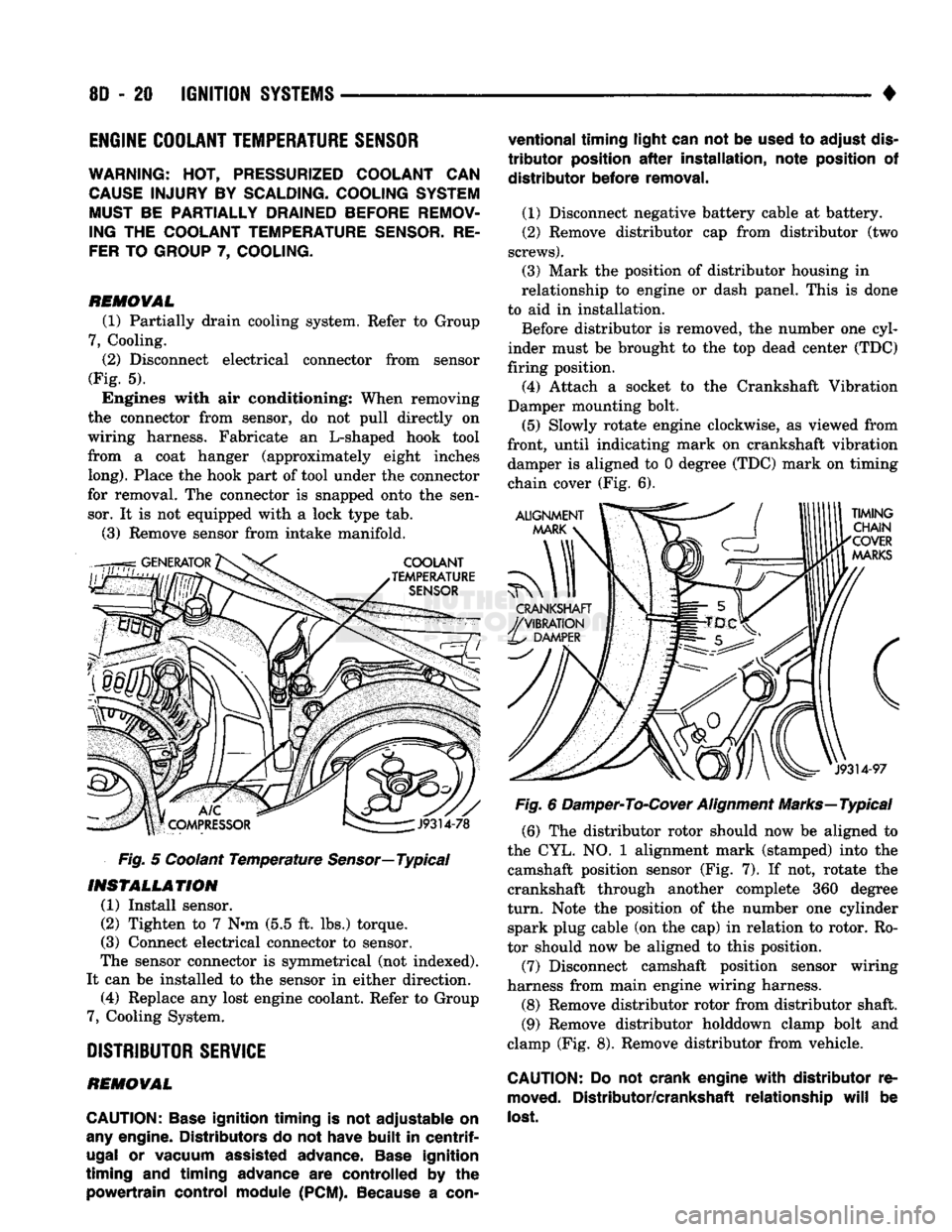
(2)
Disconnect electrical connector from sensor
(Fig. 5). Engines with air conditioning: When removing
the connector from sensor, do not pull directly on
wiring harness. Fabricate an L-shaped hook tool
from a coat hanger (approximately eight inches
long).
Place the hook part of tool under the connector
for removal. The connector is snapped onto the sen sor. It is not equipped with a lock type tab.
(3) Remove sensor from intake manifold.
Fig. 5 Coolant Temperature
Sensor—
Typical
INSTALLATION
(1) Install sensor.
(2) Tighten to 7 Nnn (5.5 ft. lbs.) torque.
(3) Connect electrical connector to sensor.
The sensor connector is symmetrical (not indexed).
It can be installed to the sensor in either direction. (4) Replace any lost engine coolant. Refer to Group
7, Cooling System.
DISTRIBUTOR
SERVICE
REMOVAL
CAUTION:
Base
ignition timing
is not
adjustable
on
any
engine. Distributors
do not
have
built
in
centrif
ugal
or
vacuum assisted advance.
Base
ignition
timing
and
timing advance
are
controlled
by the
powertrain control module
(PCM).
Because
a
con
ventional timing light can
not be
used
to
adjust
dis
tributor
position
after
installation, note position
of
distributor before removal.
(1) Disconnect negative battery cable at battery.
(2) Remove distributor cap from distributor (two
screws).
(3) Mark the position of distributor housing in
relationship to engine or dash panel. This is done
to aid in installation. Before distributor is removed, the number one cyl
inder must be brought to the top dead center (TDC)
firing position. (4) Attach a socket to the Crankshaft Vibration
Damper mounting bolt.
(5) Slowly rotate engine clockwise, as viewed from
front, until indicating mark on crankshaft vibration damper is aligned to 0 degree (TDC) mark on timing
chain cover (Fig. 6).
Fig. 6 Damper-To-Cover Alignment Marks—Typical (6) The distributor rotor should now be aligned to
the CYL. NO. 1 alignment mark (stamped) into the camshaft position sensor (Fig. 7). If not, rotate the
crankshaft through another complete 360 degree
turn.
Note the position of the number one cylinder spark plug cable (on the cap) in relation to rotor. Ro
tor should now be aligned to this position.
(7) Disconnect camshaft position sensor wiring
harness from main engine wiring harness.
(8) Remove distributor rotor from distributor shaft. (9) Remove distributor holddown clamp bolt and
clamp (Fig. 8). Remove distributor from vehicle.
CAUTION: Do not
crank engine
with
distributor
re
moved.
Distributor/crankshaft relationship
will
be
lost.
Page 760 of 1502
•
EXHAUST SYSTEM
AND
INTAKE MANIFOLD
11-1
CONTENTS
page
EXHAUST SYSTEM DIAGNOSIS
3
GENERAL
INFORMATION
1
SERVICE
PROCEDURES (DIESEL ENGINES)
. 17
page
SERVICE
PROCEDURES (GASOLINE ENGINES)
. 4
SPECIFICATIONS
27
GENERAL INFORMATION
EXHAUST SYSTEM
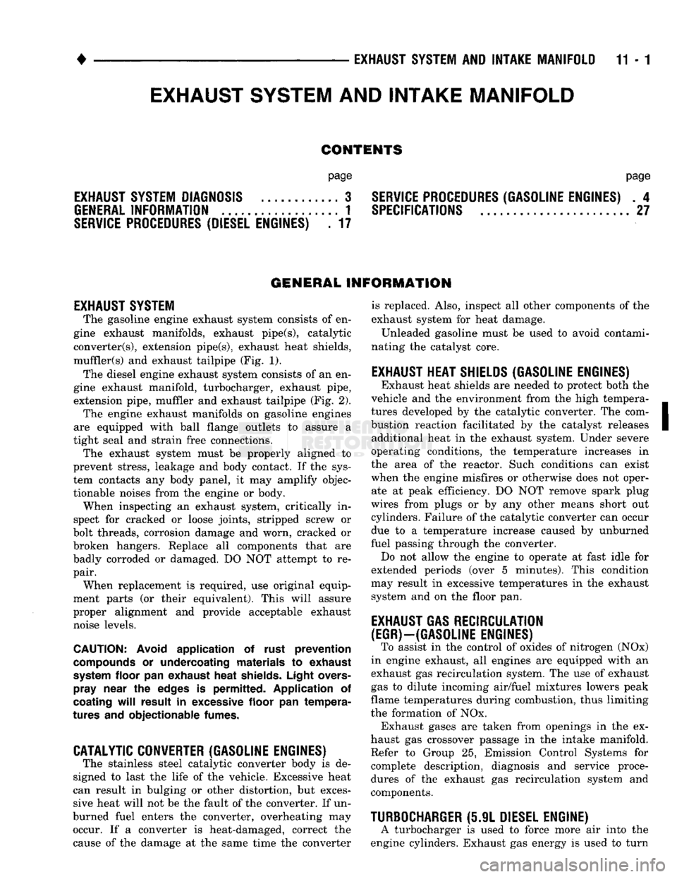
The gasoline engine exhaust system consists
of en
gine exhaust manifolds, exhaust pipe(s), catalytic converter(s), extension pipe(s), exhaust heat shields,
muffler(s)
and
exhaust tailpipe
(Fig. 1).
The diesel engine exhaust system consists
of an en
gine exhaust manifold, turbocharger, exhaust pipe,
extension pipe, muffler
and
exhaust tailpipe
(Fig. 2).
The engine exhaust manifolds
on
gasoline engines
are equipped with ball flange outlets
to
assure
a
tight seal
and
strain free connections. The exhaust system must
be
properly aligned
to
prevent stress, leakage
and
body contact.
If the
sys
tem contacts
any
body panel,
it may
amplify objec
tionable noises from
the
engine
or
body. When inspecting
an
exhaust system, critically
in
spect
for
cracked
or
loose joints, stripped screw
or
bolt threads, corrosion damage
and
worn, cracked
or
broken hangers. Replace
all
components that
are
badly corroded
or
damaged.
DO NOT
attempt
to re
pair. When replacement
is
required,
use
original equip
ment parts
(or
their equivalent). This will assure
proper alignment
and
provide acceptable exhaust
noise levels.
CAUTION:
Avoid
application
of
rust
prevention
compounds
or
undercoating materials
to
exhaust
system
floor
pan
exhaust
heat
shields.
Light
overs-
pray
near
the
edges
is
permitted. Application
of
coating
will
result
in
excessive
floor
pan
tempera
tures
and
objectionable
fumes.
CATALYTIC CONVERTER (GASOLINE ENGINES)
The stainless steel catalytic converter body
is de
signed
to
last
the
life
of the
vehicle. Excessive heat
can result
in
bulging
or
other distortion,
but
exces sive heat will
not be the
fault
of the
converter.
If un-
burned fuel enters
the
converter, overheating
may
occur.
If a
converter
is
heat-damaged, correct
the
cause
of the
damage
at the
same time
the
converter is replaced. Also, inspect
all
other components
of the
exhaust system
for
heat damage.
Unleaded gasoline must
be
used
to
avoid contami
nating
the
catalyst core.
EXHAUST HEAT SHIELDS (GASOLINE ENGINES)
Exhaust heat shields
are
needed
to
protect both
the
vehicle
and the
environment from
the
high tempera
tures developed
by the
catalytic converter.
The
com
bustion reaction facilitated
by the
catalyst releases additional heat
in the
exhaust system. Under severe
operating conditions,
the
temperature increases
in
the area
of the
reactor. Such conditions
can
exist
when
the
engine misfires
or
otherwise does
not
oper ate
at
peak efficiency.
DO NOT
remove spark plug
wires from plugs
or by any
other means short
out
cylinders. Failure
of the
catalytic converter
can
occur
due
to a
temperature increase caused
by
unburned
fuel passing through
the
converter. Do
not
allow
the
engine
to
operate
at
fast idle
for
extended periods (over
5
minutes). This condition
may result
in
excessive temperatures
in the
exhaust system
and on the
floor
pan.
EXHAUST GAS RECIRCULATION
(EGR)—(GASOLINE ENGINES)
To assist
in the
control
of
oxides
of
nitrogen
(NOx)
in engine exhaust,
all
engines
are
equipped with
an
exhaust
gas
recirculation system.
The use of
exhaust
gas
to
dilute incoming air/fuel mixtures lowers peak
flame temperatures during combustion, thus limiting
the formation
of NOx.
Exhaust gases
are
taken from openings
in the ex
haust
gas
crossover passage
in the
intake manifold. Refer
to
Group
25,
Emission Control Systems
for
complete description, diagnosis
and
service proce
dures
of the
exhaust
gas
recirculation system
and
components.
TURBOCHARGER
(5.9L
DIESEL ENGINE)
A turbocharger
is
used
to
force more
air
into
the
engine cylinders. Exhaust
gas
energy
is
used
to
turn
EXHAUST SYSTEM
AND
INTAKE MANIFOLD
Page 878 of 1502
•
FUEL SYSTEM
14 - 59
fill
DHADn
HIAf5MflCTipQ
/f|Rn
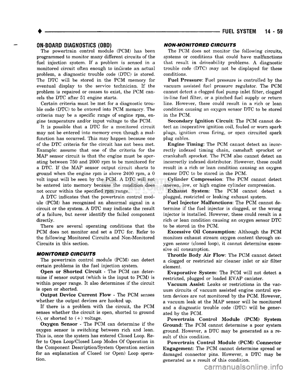
The powertrain control module (PCM) has been
programmed to monitor many different circuits of the
fuel injection system. If a problem is sensed in a monitored circuit often enough to indicate an actual
problem, a diagnostic trouble code (DTC) is stored.
The DTC will be stored in the PCM memory for eventual display to the service technician. If the
problem is repaired or ceases to exist, the PCM can cels the DTC after 51 engine starts.
Certain criteria must be met for a diagnostic trou
ble code (DTC) to be entered into PCM memory. The criteria may be a specific range of engine rpm, en
gine temperature and/or input voltage to the PCM.
It is possible that a DTC for a monitored circuit
may not be entered into memory even though a mal
function has occurred. This may happen because one
of the DTC criteria for the circuit has not been met. Example: assume that one of the criteria for the
MAP sensor circuit is that the engine must be oper ating between 750 and 2000 rpm to be monitored for
a DTC. If the MAP sensor output circuit shorts to
ground when the engine rpm is above 2400 rpm, a 0
volt input will be seen by the PCM. A DTC will not
be entered into memory because the condition does not occur within the specified rpm range.
A DTC indicates that the powertrain control mod
ule (PCM) has recognized an abnormal signal in a
circuit or the system. A DTC may indicate the result
of a failure, but never identify the failed component
directly.
There are several operating conditions that the
PCM does not monitor and set a DTC for. Refer to
the following Monitored Circuits and Non-Monitored Circuits in this section.
MONITORED
CIRCUITS
The powertrain control module (PCM) can detect
certain problems in the fuel injection system.
Open or Shorted Circuit - The PCM can deter
mine if sensor output (which is the input to PCM) is
within proper range. It also determines if the circuit is open or shorted.
Output Device Current Flow - The PCM senses
whether the output devices are hooked up.
If there is a problem with the circuit, the PCM
senses whether the circuit is open, shorted to ground
(-), or shorted to
(
+
)
voltage.
Oxygen Sensor - The PCM can determine if the
oxygen sensor is switching between rich and lean.
This is, once the system has entered Closed Loop. Re fer to Open Loop/Closed Loop Modes Of Operation in
the Component Description/System Operation section
for an explanation of Closed (or Open) Loop opera tion.
NON-MONITORED CIRCUITS
The PCM does not monitor the following circuits,
systems or conditions that could have malfunctions
that result in driveability problems. A diagnostic trouble code (DTC) may not be displayed for these
conditions.
Fuel Pressure: Fuel pressure is controlled by the
vacuum assisted fuel pressure regulator. The PCM
cannot detect a clogged fuel pump inlet filter, clogged
in-line fuel filter, or a pinched fuel supply or return
line.
However, these could result in a rich or lean
condition causing an oxygen sensor DTC to be stored in the PCM.
Secondary Ignition Circuit: The PCM cannot de
tect an inoperative ignition coil, fouled or worn spark
plugs,
ignition cross firing, or open circuited spark
plug cables.
Engine Timing: The PCM cannot detect an incor
rectly indexed timing chain, camshaft sprocket or crankshaft sprocket. The PCM also cannot detect an
incorrectly indexed distributor. However, these could
result in a rich or lean condition causing an oxygen
sensor DTC to be stored in the PCM.
Cylinder Compression: The PCM cannot detect
uneven, low, or high engine cylinder compression.
Exhaust System: The PCM cannot detect
a
plugged, restricted or leaking exhaust system.
Fuel Injector Malfunctions: The PCM cannot de
termine if the fuel injector is clogged, or the wrong injector is installed. However, these could result in a
rich or lean condition causing an oxygen sensor DTC
to be stored in the PCM.
Excessive Oil Consumption: Although the PCM
monitors exhaust stream oxygen content through ox
ygen sensor (closed loop), it cannot determine exces sive oil consumption.
Throttle Body Air Flow: The PCM cannot detect
a clogged or restricted air cleaner inlet or air filter
element.
Evaporative System: The PCM will not detect a
restricted, plugged or loaded EVAP canister. Vacuum Assist: Leaks or restrictions in the vac
uum circuits of vacuum assisted engine control sys
tem devices are not monitored by the PCM. However, a vacuum leak at the MAP sensor will be monitored
and a diagnostic trouble code (DTC) will be gener
ated by the PCM.
Powertrain Control Module (PCM) System
Ground: The PCM cannot determine a poor system
ground. However, a DTC may be generated as a re
sult of this condition.
Powertrain Control Module (PCM) Connector
Engagement: The PCM cannot determine spread or
damaged connector pins. However, a DTC may be generated as a result of this condition.