1993 DODGE TRUCK glove box
[x] Cancel search: glove boxPage 334 of 1502
•
ELECTRICAL
8A - 13 GENERATOR TEST PROCEDURES ON
VEHICLE
INDEX
page
Current
Output
Test
......................
14
Diagnostic Procedures
13
General
Information
13
Generator
Output
Wire Resistance Test
.......
13
page
How
to
Use
Malfunction
Indicator
(Check Engine) Lamp
for
Fault
Codes
17
Operational Check
with
Voltmeter
............
13
Using
On-Board Diagnostic System
15
GENERAL
INFORMATION
The generator
is
belt-driven
by the
engine.
All en
gines
use
serpentine drive. The amount
of DC
current produced
by the
gener
ator
is
controlled
by the
Powertrain Control Module (PCM).
All vehicles
are
equipped with
On
Board Diagnos
tics (OBD).
All OBD
sensing systems
are
monitored
by
the PCM. The PCM
will store
in
electronic mem ory
any
detectable failure within
the
monitored cir
cuits.
Refer
to
USING ON-BOARD DIAGNOSTIC SYSTEM
in
this group
for
more information.
OPERATIONAL CHECK
WITH
VOLTMETER
When
the
ignition switch
is
turned
to the RUN po
sition, battery potential will register
on the
voltme
ter. During engine cranking
a
lower voltage will appear
on the
meter. With
the
engine running,
a
voltage reading higher than
the
first reading (igni
tion
in RUN)
should register.
DIAGNOSTIC PROCEDURES
If
the
indicator does
not
operate properly,
or if an
undercharged
or
overcharged battery condition
oc
curs,
the
following procedures
may be
used
to
diag
nose
the
charging system. Remember that
an
undercharged battery
is
often
caused
by:
• accessories being left
on
overnight
•
or by a
defective switch which allows
a
bulb, such
as a
trunk
or
glove
box
light,
to
stay
on
(refer
to
Ignition
Off
Draw).
WISUAL
INSPECTION
• Inspect condition
of
battery cable terminals, bat
tery posts, connections
at
engine block, starter motor solenoid
and
relay. They should
be
clean
and
tight.
Repair
as
required.
• Inspect
all
fuses
in the
fuse block
for
tightness
in
receptacles. They should
be
properly installed
and
tight. Repair
or
replace
as
required.
• Inspect generator mounting bolts
for
tightness.
Re
place
or
torque bolt
as
required (refer
to
Torque Specifications).
• Inspect generator drive belt condition
and
tension.
Tension
or
replace belt
as
required. Refer
to
Belt
Tension Specifications. • Inspect connection
at
generator
B+
output.
It
should
be
clean
and
tight. Repair
as
required.
GENERATOR
OUTPUT
WIRE RESISTANCE TEST
(FIG.
1)
Generator output wire resistance test will show
amount
of
voltage drop across generator output wire
between generator
BAT
terminal
and
battery posi tive post.
PREPARATION
(1) Before starting test make sure vehicle
has a
fully charged battery. Test
and
procedures
on how to
check
for a
fully charged battery
are
shown
in
Bat
tery section
of
this Group.
(2) Turn
OFF
ignition switch.
(3)
Disconnect negative cable from battery.
(4)
Disconnect generator output wire from genera
tor output Battery terminal. (5) Connect
a 0-150
ampere scale
D.C.
ammeter
in
series between generator
BAT
terminal
and
discon
nected generator output wire. Connect Positive lead
to generator
BAT
terminal
and
Negative lead
to
dis connected generator output wire. (6) Connect Positive lead
of a
test voltmeter
(Range
0-18
volts minimum)
to
disconnected genera
tor output wire. Connect negative lead
of
test voltme
ter
to
battery positive cable
at
positive post. (7) Connect
one end of a
Jumper Wire
to
ground
and with other
end
probe green
K20
lead wire
at
back
of
generator
(Fig. 1).
(This will generate
a
fault
code).
CAUTION:
Do not
connect blue
A142
lead
of
wiring
to ground. Refer
to
Group
8W
-
Wiring Diagrams
for
more information.
(8) Connect
an
engine tachometer
and
connect neg
ative cable
to
battery.
(9) Connect
a
variable carbon pile rheostat
be
tween battery terminals.
Be
sure carbon pile
is in
"Open"
or "Off
position before connecting leads.
See
Battery Section, Load Testing
for
instructions.
TEST
(1) Start engine. Immediately after starting,
re
duce engine speed
to
idle.
Page 397 of 1502
8E - 16 INSTRUMENT PANEL AND GAUGES
• SWITCH AND
PANEL
COMPONENT
SERVICE
INDEX
page
Ash
Tray
20
Cigar
Lighter
........................ 20
Four
Wheel Drive
Indicator
19
Fuse
Block
and
Flashers
................... 19
Glove
Box 21
Heater A/C Control
17
page
Heater Control
16
Hood
Release
19
Illumination
Bulb Replacement
22
Message
Center Module
................... 18
Steering Column Lowering
and
Raising
16
Switches
17
DISCONNECT NEGATIVE CABLE FEOM
BATTERY IN ENGINE COMPAETMENT BE FORE SERVICING INSTRUMENT PANEL.
STEERING COLUMN LOWERING AND RAISING When servicing the instrument panel and the Low
ering and Raising of the steering column is required,
the following is the procedure for doing so: This procedure is not for removing and replac
ing the steering column. Refer to Group - 19 Steering of this manual for the removal and re
placement procedures.
LOWERING STEERING COLUMN
(1) Disconnect negative cable from battery.
(2)
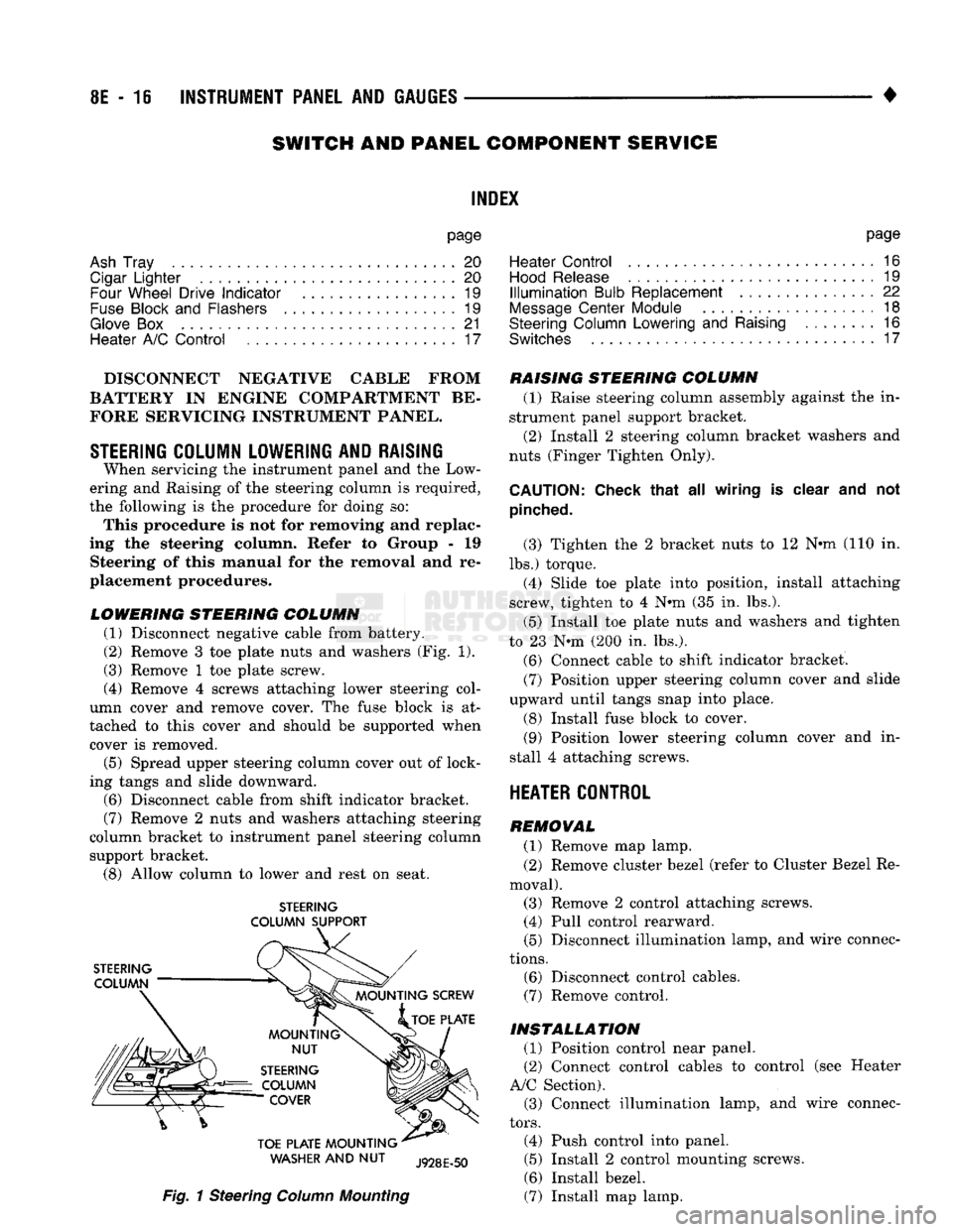
Remove 3 toe plate nuts and washers (Fig. 1).
(3) Remove 1 toe plate screw.
(4) Remove 4 screws attaching lower steering col
umn cover and remove cover. The fuse block is at
tached to this cover and should be supported when cover is removed.
(5) Spread upper steering column cover out of lock
ing tangs and slide downward.
(6)
Disconnect cable from shift indicator bracket.
(7)
Remove 2 nuts and washers attaching steering
column bracket to instrument panel steering column support bracket.
(8)
Allow column to lower and rest on seat.
STEERING
COLUMN SUPPORT
WASHER
AND NUT
Fig.
1 Steering
Column
Mounting
RAISING STEERING COLUMN
(1) Raise steering column assembly against the in
strument panel support bracket. (2) Install 2 steering column bracket washers and
nuts (Finger Tighten Only).
CAUTION:
Check that
all
wiring
is
clear
and not
pinched.
(3) Tighten the 2 bracket nuts to 12 Nnn-(110 in.
lbs.) torque. (4) Slide toe plate into position, install attaching
screw, tighten to 4 N®m (35 in. lbs.).
(5) Install toe plate nuts and washers and tighten
to 23 N*m (200 in. lbs.).
(6)
Connect cable to shift indicator bracket.
(7)
Position upper steering column cover and slide
upward until tangs snap into place.
(8) Install fuse block to cover.
(9)
Position lower steering column cover and in
stall 4 attaching screws.
HEATER CONTROL
REMOVAL
(1) Remove map lamp.
(2) Remove cluster bezel (refer to Cluster Bezel Re
moval). (3) Remove 2 control attaching screws. (4) Pull control rearward.
(5) Disconnect illumination lamp, and wire connec
tions.
(6)
Disconnect control cables.
(7)
Remove control.
INSTALLATION
(1) Position control near panel.
(2) Connect control cables to control (see Heater
A/C Section). (3) Connect illumination lamp, and wire connec
tors.
(4) Push control into panel.
(5) Install 2 control mounting screws.
(6)
Install bezel.
(7)
Install map lamp.
Page 399 of 1502
8E
- 18
INSTRUMENT PANEL
AND
GAUGES
—
•
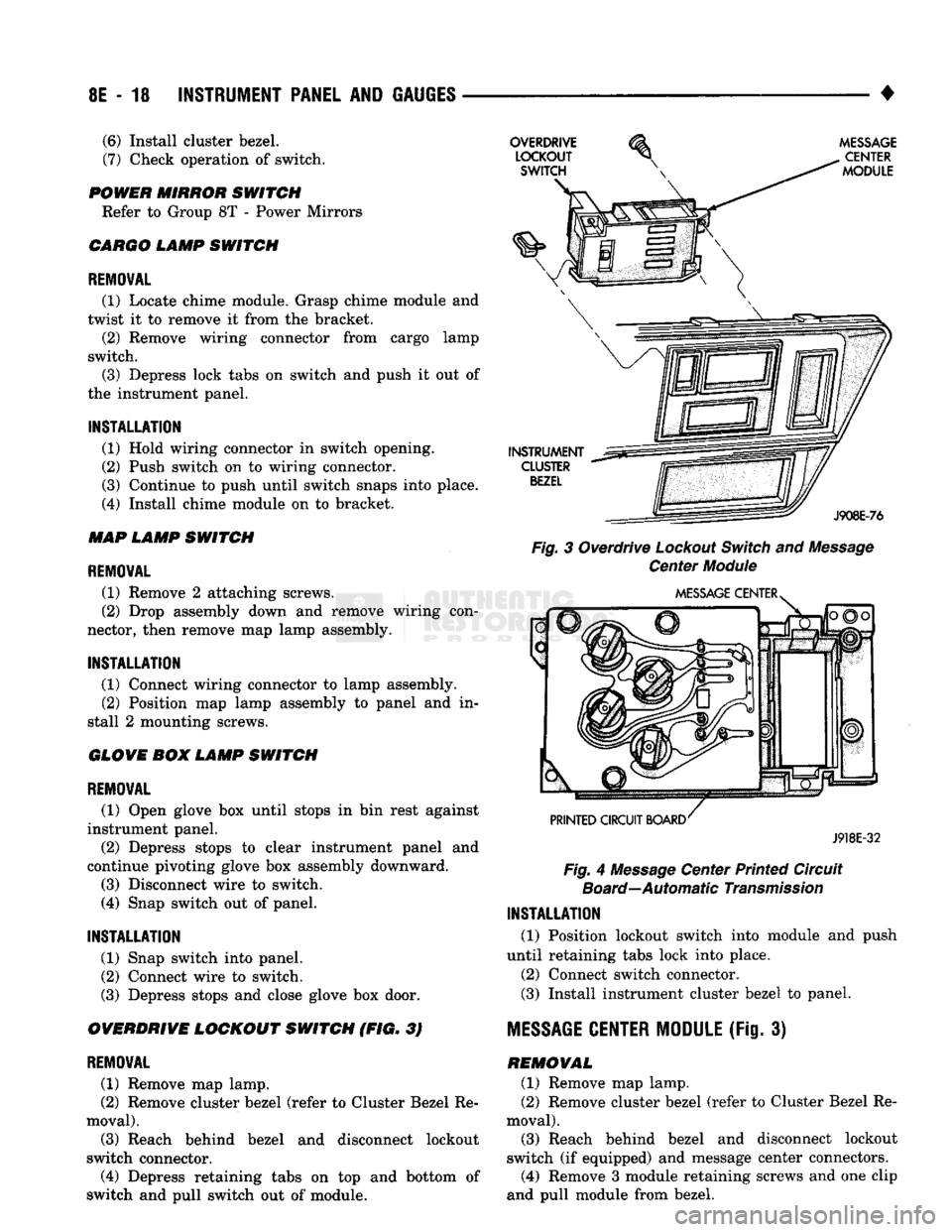
Fig.
3 Overdrive
Lockout
Switch
and
Message
Center
Module
J918E-32
Fig.
4
Message
Center Printed Circuit
Board—Automatic
Transmission
INSTALLATION
(1) Position lockout switch into module and push
until retaining tabs lock into place.
(2) Connect switch connector.
(3)
Install instrument cluster bezel to panel.
MESSAGE
CENTER MODULE
(Fig. 3) REMOVAL (1) Remove map lamp.
(2) Remove cluster bezel (refer to Cluster Bezel Re
moval).
(3)
Reach behind bezel and disconnect lockout
switch (if equipped) and message center connectors.
(4)
Remove 3 module retaining screws and one clip
and pull module from bezel.
(6)
Install cluster bezel.
(7)
Check operation of switch.
POWER MIRROR SWITCH Refer to Group 8T - Power Mirrors
CARGO LAMP SWITCH
REMOVAL
(1) Locate chime module. Grasp chime module and
twist it to remove it from the bracket. (2) Remove wiring connector from cargo lamp
switch.
(3)
Depress lock tabs on switch and push it out of
the instrument panel.
INSTALLATION
(1) Hold wiring connector in switch opening.
(2) Push switch on to wiring connector.
(3)
Continue to push until switch snaps into place.
(4)
Install chime module on to bracket.
MAP LAMP SWITCH
REMOVAL
(1) Remove 2 attaching screws.
(2) Drop assembly down and remove wiring con
nector, then remove map lamp assembly.
INSTALLATION
(1) Connect wiring connector to lamp assembly. (2) Position map lamp assembly to panel and in
stall 2 mounting screws.
GLOVE BOX LAMP SWITCH
REMOVAL
(1) Open glove box until stops in bin rest against
instrument panel.
(2) Depress stops to clear instrument panel and
continue pivoting glove box assembly downward.
(3)
Disconnect wire to switch.
(4)
Snap switch out of panel.
INSTALLATION
(1) Snap switch into panel.
(2) Connect wire to switch.
(3)
Depress stops and close glove box door.
OVERDRIVE LOCKOUT SWITCH (FIG. 3)
REMOVAL
(1) Remove map lamp.
(2) Remove cluster bezel (refer to Cluster Bezel Re
moval).
(3)
Reach behind bezel and disconnect lockout
switch connector.
(4)
Depress retaining tabs on top and bottom of
switch and pull switch out of module.
Page 402 of 1502
•
INSTRUMENT PANEL AND GAUGES 8E - 21
GLOVE
BOX
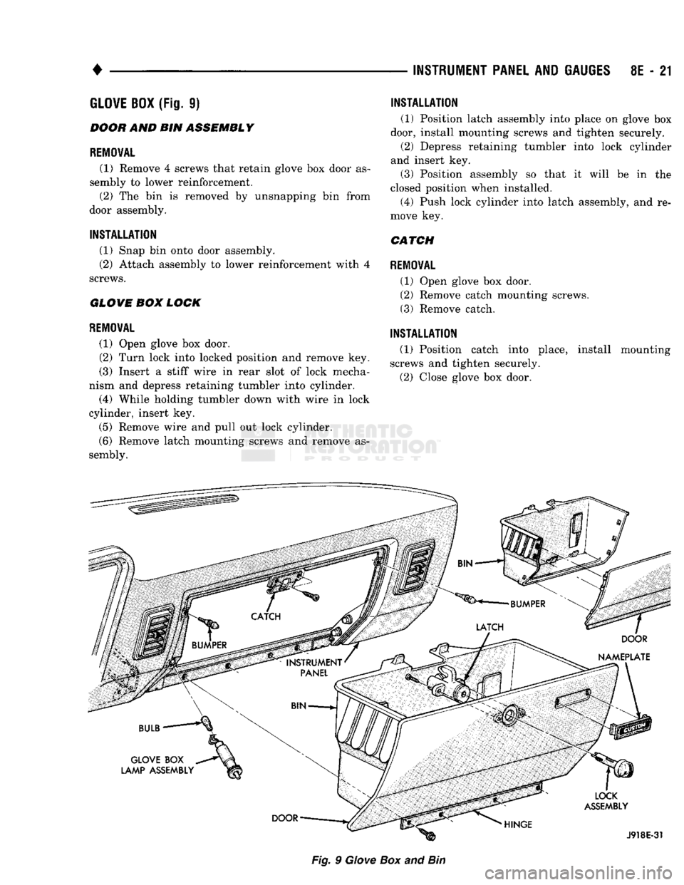
(Fig.
9)
BOOH
AND BIN
ASSEMBLY
REMOVAL
(1) Remove
4
screws that retain glove
box
door
as
sembly
to
lower reinforcement. (2)
The bin is
removed
by
unsnapping
bin
from
door assembly.
INSTALLATION
(1) Snap
bin
onto door assembly.
(2) Attach assembly
to
lower reinforcement with
4
screws.
GLOVE
BOM
LOCK
REMOVAL
(1) Open glove
box
door.
(2)
Turn lock into locked position
and
remove
key.
(3) Insert
a
stiff wire
in
rear slot
of
lock mecha
nism
and
depress retaining tumbler into cylinder.
(4) While holding tumbler down with wire
in
lock
cylinder, insert
key.
(5)
Remove wire
and
pull
out
lock cylinder.
(6) Remove latch mounting screws
and
remove
as
sembly.
INSTALLATION
(1) Position latch assembly into place
on
glove
box
door, install mounting screws
and
tighten securely. (2) Depress retaining tumbler into lock cylinder
and insert
key.
(3) Position assembly
so
that
it
will
be in the
closed position when installed. (4) Push lock cylinder into latch assembly,
and re
move
key.
CATCH
REMOVAL
(1) Open glove
box
door.
(2) Remove catch mounting screws.
(3) Remove catch.
INSTALLATION
(1) Position catch into place, install mounting
screws
and
tighten securely.
(2) Close glove
box
door.
Fig.
9
Giove
Box
and
Bin
Page 407 of 1502
8F - 4
AUDIO SYSTEMS
• ANTENNA DIAGNOSIS
Turn Ign. Key
to
ACC
Tune
to
Known
Strong AM
Station
f
Check
Antenna Connections
1
1
No
Check
for
Reception Using
A
Test Antenna Repair as
Required*
*Be
Sure
Antenna
is
Properly
Grounded
to
Car.
(Poor
Grounding
of
Antenna
May
Cause
Engine Noise
or
Yes
Static Especially on AM)
Remove
Radio
For
Service
Replace
or
Repair
Defective
Antenna
Or
Lead
in
J928F-4
TIP
OF
MAST
TEST
POINT
RY684
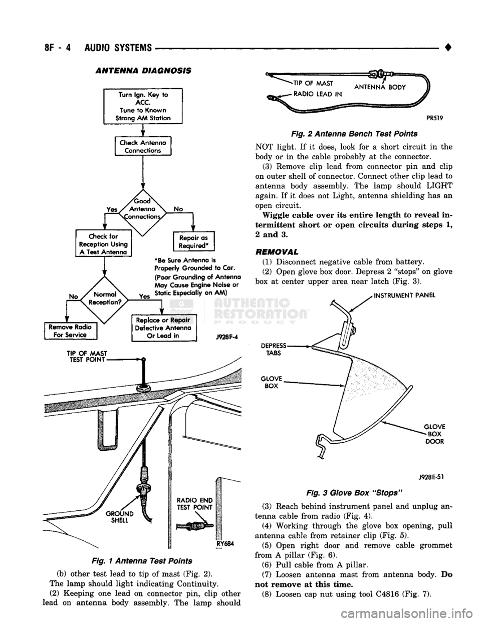
Fig. 1 Antenna Test Points
(b) other test lead to tip of mast (Fig. 2).
The lamp should light indicating Continuity. (2) Keeping one lead on connector pin, clip other
lead on antenna body assembly. The lamp should
-TIP
OF
MAST
•
RADIO LEAD
IN
PR519
Fig.
2 Antenna Bench Test
Points
NOT light. If it does, look for a short circuit in the
body or in the cable probably at the connector.
(3) Remove clip lead from connector pin and clip
on outer shell of connector. Connect other clip lead to
antenna body assembly. The lamp should LIGHT
again. If it does not Light, antenna shielding has an
open circuit.
Wiggle cable over its entire length to reveal in
termittent short or open circuits during steps 1,
2 and 3.
REMOVAL
(1) Disconnect negative cable from battery.
(2) Open glove box door. Depress 2 "stops" on glove
box at center upper area near latch (Fig. 3).
INSTRUMENT
PANEL
DEPRESS
TABS
GLOVE BOX
GLOVE
BOX
DOOR
J928E-51
Fig.
3
Glove
Box
"Stops"
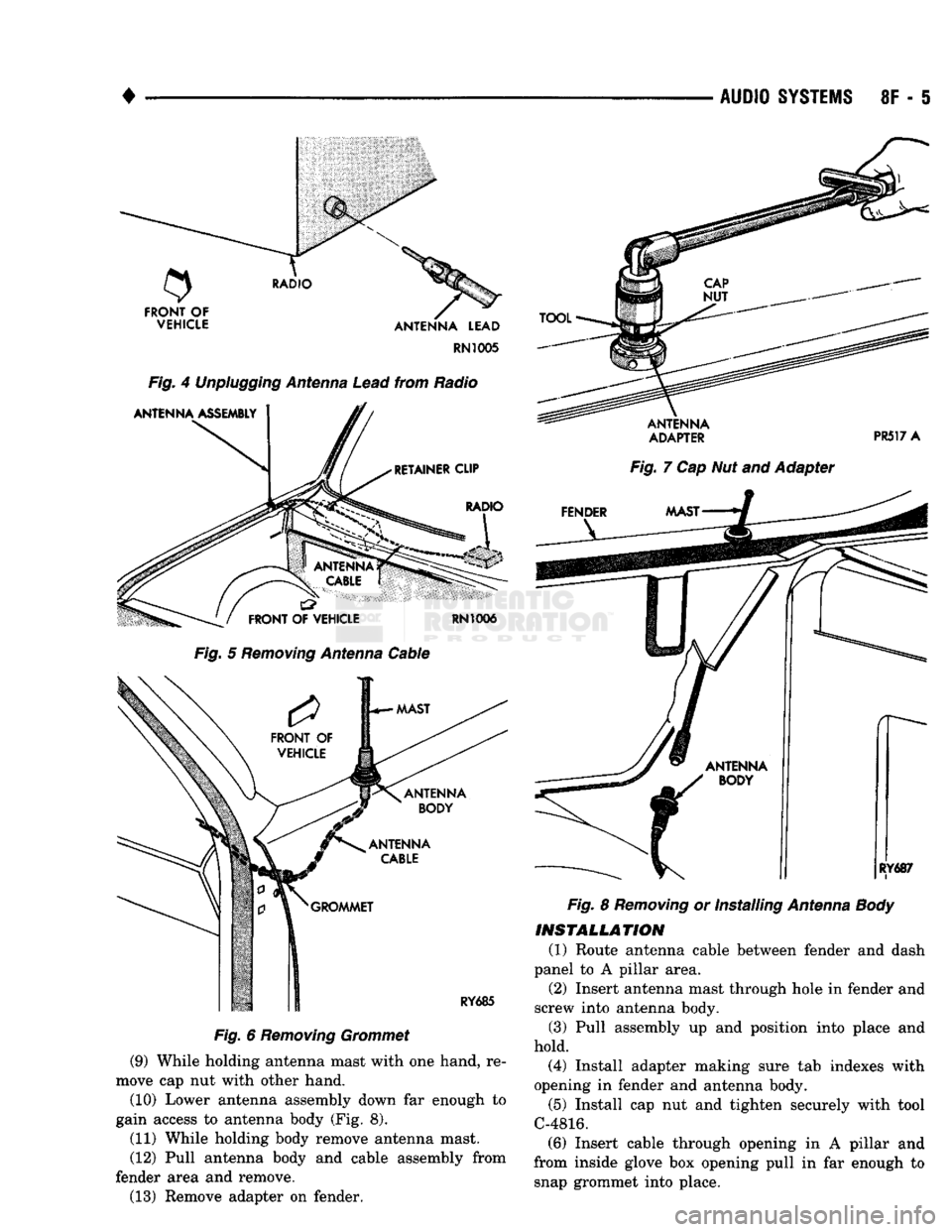
(3) Reach behind instrument panel and unplug an
tenna cable from radio (Fig. 4).
(4) Working through the glove box opening, pull
antenna cable from retainer clip (Fig. 5).
(5) Open right door and remove cable grommet
from A pillar (Fig. 6). (6) Pull cable from A pillar. (7) Loosen antenna mast from antenna body. Do
not remove at this time.
(8) Loosen cap nut using tool C4816 (Fig. 7).
Page 408 of 1502
•
AUDIO
SYSTEMS
8F - 5
RN1005
Fig.
4
Unplugging
Antenna
Lead
from Radio
Fig.
5
Removing
Antenna
Cable
Fig.
6
Removing
Grommet
(9) While holding antenna mast with one hand, re
move cap nut with other hand.
(10) Lower antenna assembly down far enough to
gain access to antenna body (Fig. 8).
(11) While holding body remove antenna mast.
(12) Pull antenna body and cable assembly from
fender area and remove. (13) Remove adapter on fender.
ADAPTER
PR517 A
Fig.
7 Cap Nut and Adapter
Fig.
8
Removing
or Installing
Antenna
Body
INSTALLATION
(1) Route antenna cable between fender and dash
panel to A pillar area. (2) Insert antenna mast through hole in fender and
screw into antenna body.
(3) Pull assembly up and position into place and
hold. (4) Install adapter making sure tab indexes with
opening in fender and antenna body.
(5) Install cap nut and tighten securely with tool
C-4816. (6) Insert cable through opening in A pillar and
from inside glove box opening pull in far enough to snap grommet into place.
Page 409 of 1502
8F
- 6
AUDIO
SYSTEMS
•
(7) Route cable through retainer clip, over to radio,
and plug into back of radio. (8) Close glove box.
(9) Connect negative cable to battery.
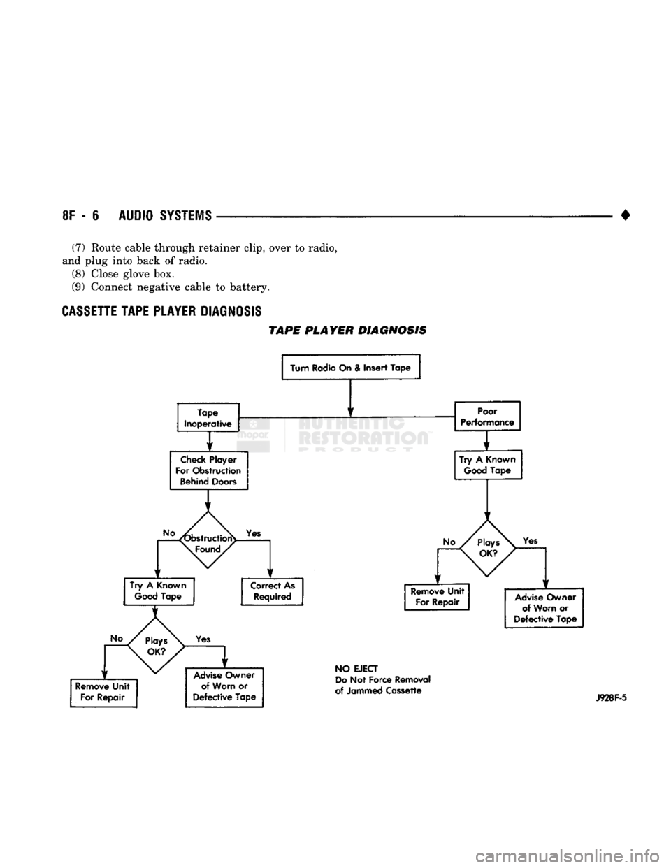
CASSETTE
TAPE
PLAYER
DIAGNOSIS
TAPE
PLAYER DIAGNOSIS
Turn Radio On & Insert Tape
Tape
Inoperative
Check
Player
For Obstruction
Behind
Doors
Poor
Performance
1
Try
A
Good
Known
Tape
Yes
Try
A
Known
Good
Tape Correct As
Required
Yes
Advise
Owner of Worn
or
Defective
Tape
Yes
Remove
Unit For Repair
Advise
Owner
of Worn
or
Defective
Tape
NO
EJECT
Do
Not Force Removal
of Jammed Cassette
J928F-5
Page 482 of 1502
CAVITY
FUSE/
COLOR ITEMS FUSED
CAVITY
FUSE/
COLOR ITEMS FUSED
10
11
12
13 2 AMP
GY VEHICLE SPEED CONTROL
5 AMP TN
GAUGES,
BRAKE WARNING LAMP, SEAT BELT WARNING
LAMP, BUZZER, LOW OIL LAMP, CHECK ENGINE LAMP,
ANTI-LOCK LAMP, TAILGATE OPEN LAMP, 4WD LAMP, O/D MODULE, LOW FUEL LAMP,
WAIT
TO START LAMP
WATER-IN-FUEL LAMP 14
3 AMP
VT
20 AMP YL BACK-UP LAMP, HEATED REAR WINDOW
15 10 AMP
RD
ILLUMINATION
LAMPS, A/C HEATER LAMP, ASH
RECEIVER LAMP, RADIO LAMP, TRANSMISSION
OVERDRIVE SWITCH LAMP, TACHOMETER LAMP, HEATED REAR WINDOW SWITCH LAMP.
RADIO AND CLOCK MEMORY, POWER MIRRORS, GLOVE BOX LAMP, DOME LAMP, READING LAMP, MAP LAMP,
CARGO LAMP,
IGNITION
SWITCH LAMP, UNDERHOOD LAMP
20 AMP YL FUSE CAVITY #14,
TAIL
LAMPS, PARKING LAMPS, SIDE
AAARKER
LAMPS, LICENSE LAMPS, FRONT AND REAR CLEARANCE LAMPS, RADIO INTENSITY, HORNS
20 AMP YL STOP LAMPS, KEY-IN & HEADLAMP ON BUZZER, RWAL
MODULE 30 AMP
CIRCUIT
BREAKER
TURN
SIGNAL
FLASHER 20 AMP
YL POWER DOOR LOCKS
15 AMP
BL
CIGAR LIGHTER
10 AMP RD RADIO AND CLOCK
20 AMP YL
TURN
SIGNALS, TACHOMETER PROVISION,
RWAL MODULE
20 AMP YL WINDSHIELD WIPERS
30 AMP LG A/C - HEATER BLOWER MOTOR
30 AMP
C/BRKR
POWER WINDOWS
20 AMP YL HAZARD FLASHER
AMPS
FUSE
COLOR
2 GY GRAY
3 VT
VIOLET
5 TN
TAN
10 RD
RED
15
BL
BLUE
20 YL YELLOW
30 LG
LIGHT
GREEN HAZARD
FLASHER
J938W-94
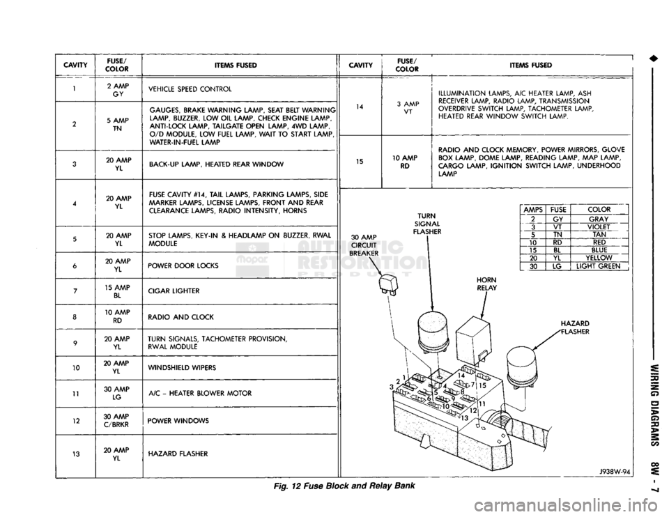
Fig. 12 Fuse Block and
Relay
Bank