1993 DODGE TRUCK fuel cap release
[x] Cancel search: fuel cap releasePage 609 of 1502
9
- 4 ENGINES
•
RN861
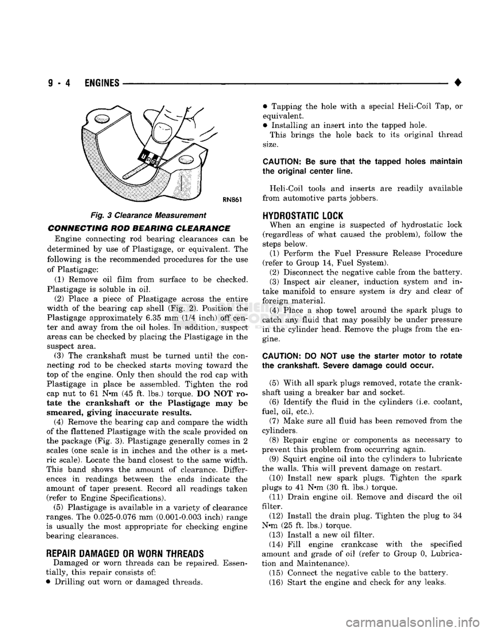
Fig. 3 Clearance Measurement
CONNECTING ROD BEARING CLEARANCE Engine connecting rod bearing clearances can be
determined by use of Plastigage, or equivalent. The
following is the recommended procedures for the use of Plastigage:
(1) Remove oil film from surface to be checked.
Plastigage is soluble in oil.
(2) Place a piece of Plastigage across the entire
width of the bearing cap shell (Fig. 2). Position the
Plastigage approximately 6.35 mm (1/4 inch) off cen
ter and away from the oil holes. In addition, suspect areas can be checked by placing the Plastigage in the
suspect area. (3) The crankshaft must be turned until the con
necting rod to be checked starts moving toward the
top of the engine. Only then should the rod cap with
Plastigage in place be assembled. Tighten the rod
cap nut to 61 Nnn (45 ft. lbs.) torque. DO NOT ro
tate the crankshaft or the Plastigage may be smeared, giving inaccurate results. (4) Remove the bearing cap and compare the width
of the flattened Plastigage with the scale provided on
the package (Fig. 3). Plastigage generally comes in 2 scales (one scale is in inches and the other is a met
ric scale). Locate the band closest to the same width.
This band shows the amount of clearance. Differ ences in readings between the ends indicate the
amount of taper present. Record all readings taken (refer to Engine Specifications). (5) Plastigage is available in a variety of clearance
ranges. The 0.025-0.076 mm (0.001-0.003 inch) range
is usually the most appropriate for checking engine
bearing clearances.
REPAIR DAMAGED OR WORN THREADS Damaged or worn threads can be repaired. Essen
tially, this repair consists of:
• Drilling out worn or damaged threads. • Tapping the hole with a special Heli-Coil Tap, or
equivalent.
• Installing an insert into the tapped hole.
This brings the hole back to its original thread
size.
CAUTION:
Be
sure
that
the tapped holes maintain
the original
center
line.
Heli-Coil tools and inserts are readily available
from automotive parts jobbers.
HYDROSTATIC
LOCK
When an engine is suspected of hydrostatic lock
(regardless of what caused the problem), follow the
steps below. (1) Perform the Fuel Pressure Release Procedure
(refer to Group 14, Fuel System). (2) Disconnect the negative cable from the battery.
(3) Inspect air cleaner, induction system and in
take manifold to ensure system is dry and clear of
foreign material. (4) Place a shop towel around the spark plugs to
catch any fluid that may possibly be under pressure
in the cylinder head. Remove the plugs from the en
gine.
CAUTION:
DO NOT use the starter motor to
rotate
the
crankshaft.
Severe
damage
could
occur.
(5) With all spark plugs removed, rotate the crank
shaft using a breaker bar and socket.
(6) Identify the fluid in the cylinders (i.e. coolant,
fuel, oil, etc.).
(7) Make sure all fluid has been removed from the
cylinders. (8) Repair engine or components as necessary to
prevent this problem from occurring again.
(9) Squirt engine oil into the cylinders to lubricate
the walls. This will prevent damage on restart.
(10) Install new spark plugs. Tighten the spark
plugs to 41 N#m (30 ft. lbs.) torque. (11) Drain engine oil. Remove and discard the oil
filter.
(12) Install the drain plug. Tighten the plug to 34
N-m (25 ft. lbs.) torque.
(13) Install a new oil filter.
(14) Fill engine crankcase with the specified
amount and grade of oil (refer to Group 0, Lubrica
tion and Maintenance). (15) Connect the negative cable to the battery.
(16) Start the engine and check for any leaks.
Page 625 of 1502
TRANSFER
CASE
INSULATOR
MOUNTING PLATE
NUT(B
RAIL
ASSEMBLY
SPACER
UPPER
INSULATOR
NUT®
LOWER
INSULATOR
J9109-242
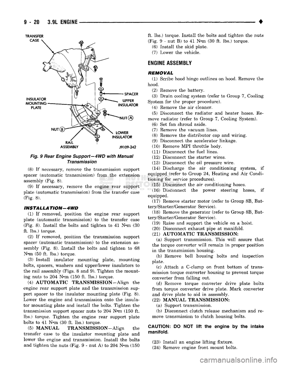
Fig.
9 Rear
Engine
Support—4WD
with
Manual
Transmission
(8) If necessary, remove the transmission support
spacer (automatic transmission) from the extension
assembly (Fig. 8).
(9) If necessary, remove the engine rear support
plate (automatic transmission) from the transfer case (Fig. 8).
INSTALLATION-4WD
(1) If removed, position the engine rear support
plate (automatic transmission) to the transfer case (Fig. 8). Install the bolts and tighten to 41 N-m (30
ft. lbs.) torque.
(2) If removed, position the transmission support
spacer (automatic transmission) to the extension as
sembly (Fig. 8). Install the bolts and tighten to 68 N-m (50 ft. lbs.) torque.
(3) Install insulator mounting plate, mounting
bolts,
spacers, washers and upper/lower insulators to
the rail assembly (Figs. 8 and 9). Tighten the mount
ing nuts to 204 N*m (150 ft. lbs.) torque.
(4) AUTOMATIC TRANSMISSION-Align the
engine rear support plate and the transmission sup
port spacer to the insulator mounting plate (Fig. 8). Lower the engine and transmission onto the insula
tor mounting plate and install the bolts. Tighten the transmission support spacer nuts to 204 N-m (150 ft. lbs.) torque. Tighten the engine rear support plate
bolts to 41 N-m (30 ft. lbs.) torque.
(5) MANUAL TRANSMISSION—Align the
transfer case to the insulator mounting plate and lower the engine and transmission. Install the bolts and tighten the nuts (Fig. 9 - nut A) to 204 N-m (150 ft. lbs.) torque. Install the bolts and tighten the nuts
(Fig. 9 - nut B) to 41 N-m (30 ft. lbs.) torque. (6) Install the skid plate.
(7) Lower the vehicle.
ENGINE
ASSEMBLY
REMOVAL (1) Scribe hood hinge outlines on hood. Remove the
hood.
(2) Remove the battery. (3) Drain cooling system (refer to Group 7, Cooling
System for the proper procedure).
(4) Remove the air cleaner. (5) Disconnect the radiator and heater hoses. Re
move radiator (refer to Group 7, Cooling System).
(6) Set fan shroud aside. (7) Remove the vacuum lines. (8) Remove the distributor cap and wiring.
(9) Disconnect the accelerator linkage.
(10) Remove MPI throttle body. (11) Disconnect the fuel lines. (12) Disconnect the starter wires.
(13) Disconnect the oil pressure wire. (14) Discharge the air conditioning system, if
equipped (refer to Group 24, Heating and Air Condi
tioning for service procedures). (15) Disconnect the air conditioning hoses.
(16) Disconnect the power steering hoses, if
equipped. (17) Remove starter motor (refer to Group 8B, Bat
tery/Starter/Generator Service). (18) Remove the generator (refer to Group 8B, Bat
tery/Starter/Generator Service).
(19) Raise and support the vehicle on a hoist.
(20) Disconnect exhaust pipe at manifold.
(21) AUTOMATIC TRANSMISSION: (a) Support transmission. This will assure that
the torque converter will remain in proper position in the transmission housing. (b) Remove bell housing bolts and inspection
plate.
(c) Attach a C-clamp on front bottom of trans
mission torque converter housing to prevent torque
converter from falling out.
(d) Remove torque converter drive plate bolts
from torque converter drive plate. Mark converter and drive plate to aid in assembly.
(22) MANUAL TRANSMISSION: (a) Support transmission.
(b) Disconnect clutch release mechanism and re
move transmission to clutch housing bolts.
CAUTION:
DO NOT
lift
the engine by the intake
manifold.
(23) Install an engine lifting fixture.
(24) Remove engine front mount bolts.
Page 626 of 1502
•
3.9L
ENGINE
9 - 21 (25) Lower the vehicle.
(26) On automatic transmission vehicles, discon
nect the engine from the torque converter drive
plate. On manual transmission vehicles, move engine forward until drive pinion shaft clears the clutch
disc.
Remove engine from engine compartment. (27) Install engine assembly on engine repair
stand.
INSTALLATION (1) Remove engine from the repair stand and posi
tion in the engine compartment.
(2) Install engine support fixture.
(3) Raise and support the vehicle on a hoist.
(4)
AUTOMATIC TRANSMISSION: (a) Position the torque converter and drive plate.
Install torque converter drive plate bolts. Tighten
the bolts to 31 Nnn (270 in. lbs.) torque.
(b) Install the engine front mounts.
(c) Install bell housing bolts. Tighten the bolts to
41 N-m (30 ft. lbs.) torque.
(d) Remove C-clamp.
(e) Install the inspection plate.
(5) MANUAL TRANSMISSION: (a) Position the drive pinion shaft to the clutch
disc.
(b) Connect the clutch release mechanism and
install the transmission to clutch bolts. Tighten the
bolts to 68 N-m (50 ft. lbs.) torque.
(c) Install the engine front mounts.
(6) Remove transmission support.
(7) Install exhaust pipe to manifold.
(8) Lower the vehicle.
(9) Remove engine lifting fixture.
(10) Install the generator (refer to Group 8B, Bat
tery/Starter/Generator Service). (11) Install starter motor (refer to Group 8B, Bat
tery/Starter/Generator Service). (12) Connect power steering hoses, if equipped.
(13) Connect air conditioning hoses.
(14) Evacuate and charge the air conditioning sys
tem, if equipped (refer to Group 24, Heater and Air Conditioning for service procedures). (15) Using a new gasket, install MPI throttle body.
Tighten the throttle body bolts to 23 N-m (200 in. lbs.) torque. (16) Connect the accelerator linkage.
(17) Connect the starter wires. (18) Connect the oil pressure wire.
(19) Install the distributor cap and wiring.
(20) Connect the vacuum lines.
(21) Connect the fuel lines.
(22) Install the radiator (refer to Group 7, Cooling
System). Connect the radiator hoses and heater
hoses.
(23) Install fan shroud in position. (24) Fill cooling system (refer to Group 7, Cooling
System for the proper procedures). (25) Install the air cleaner.
(26) Install the battery.
(27) Warm engine and adjust.
(28) Install hood and line up with the scribe
marks. (29) Road test vehicle.
CYLINDER
HEAD COVER
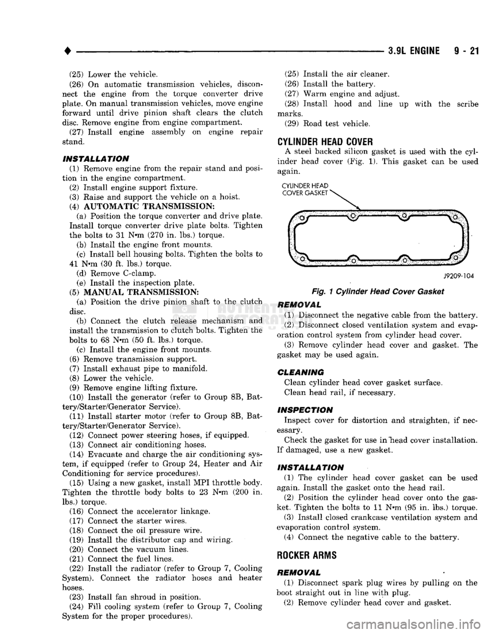
A steel backed silicon gasket is used with the cyl
inder head cover (Fig. 1). This gasket can be used again.
CYLINDER HEAD COVER GASKET
J9209-104
Fig.
1 Cylinder Head
Cover
Gasket
REMOVAL (1) Disconnect the negative cable from the battery.
(2) Disconnect closed ventilation system and evap
oration control system from cylinder head cover. (3) Remove cylinder head cover and gasket. The
gasket may be used again.
CLEANING Clean cylinder head cover gasket surface. Clean head rail, if necessary.
INSPECTION Inspect cover for distortion and straighten, if nec
essary. Check the gasket for use in "head cover installation.
If damaged, use a new gasket.
INSTALLATION (1) The cylinder head cover gasket can be used
again. Install the gasket onto the head rail.
(2) Position the cylinder head cover onto the gas
ket. Tighten the bolts to 11 N-m (95 in. lbs.) torque. (3) Install closed crankcase ventilation system and
evaporation control system.
(4) Connect the negative cable to the battery.
ROCKER
ARMS
REMOVAL (1) Disconnect spark plug wires by pulling on the
boot straight out in line with plug.
(2) Remove cylinder head cover and gasket.
Page 655 of 1502
TRANSFER
CASE
TRANSFER
CASE
ENGINE
REAR
SUPPORT PLATE
EXTENSION
ASSEMBLY
TRANSMISSION
SUPPORT
SPACER
SPACER
UPPER
INSULATOR
INSULATOR
MOUNTING
PLATE
LOWER
INSULATOR
fT^RAIL
J9109-244
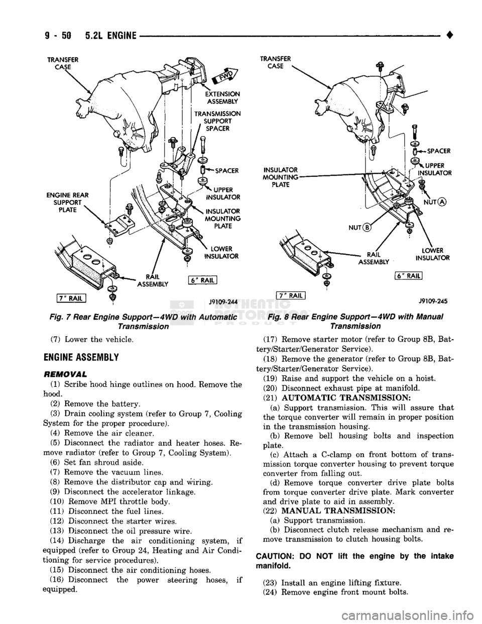
Fig,
7 Rear Engine Support—4WD
with
Automatic
Transmission
(7)
Lower the vehicle.
ENGINE
ASSEMBLY
REMOVAL
(1) Scribe hood hinge outlines on hood. Remove the
hood. (2) Remove the battery.
(3) Drain cooling system (refer to Group 7, Cooling
System for the proper procedure). (4) Remove the air cleaner.
(5) Disconnect the radiator and heater hoses. Re
move radiator (refer to Group 7, Cooling System). (6) Set fan shroud aside.
(7)
Remove the vacuum lines.
(8) Remove the distributor cap and wiring.
(9) Disconnect the accelerator linkage.
(10) Remove MPI throttle body.
(11) Disconnect the fuel lines.
(12) Disconnect the starter wires.
(13) Disconnect the oil pressure wire.
(14) Discharge the air conditioning system, if
equipped (refer to Group 24, Heating and Air Condi
tioning for service procedures).
(15) Disconnect the air conditioning hoses.
(16) Disconnect the power steering hoses, if
equipped.
INSULATOR
MOUNTING
PLATE
SPACER
UPPER
L\ f
INSULATOR
NUT®
RAIL
ASSEMBLY
LOWER
INSULATOR
l6ff
RAIL
I
J9109-245
Fig.
8 Rear
Engine
Support—4WD
with
Manual
Transmission
(17) Remove starter motor (refer to Group 8B, Bat
tery/Starter/Generator Service).
(18) Remove the generator (refer to Group 8B, Bat
tery/Starter/Generator Service).
(19) Raise and support the vehicle on a hoist.
(20) Disconnect exhaust pipe at manifold.
(21)
AUTOMATIC TRANSMISSION: (a) Support transmission. This will assure that
the torque converter will remain in proper position in the transmission housing. (b) Remove bell housing bolts and inspection
plate. (c) Attach a C-clamp on front bottom of trans
mission torque converter housing to prevent torque
converter from falling out. (d) Remove torque converter drive plate bolts
from torque converter drive plate. Mark converter and drive plate to aid in assembly.
(22)
MANUAL TRANSMISSION; (a) Support transmission.
(b) Disconnect clutch release mechanism and re
move transmission to clutch housing bolts.
CAUTION:
manifold.
DO
NOT lift the
engine
by the
intake
(23) Install an engine lifting fixture.
(24) Remove engine front mount bolts.
Page 656 of 1502
•
5.2L
ENGINE
9 - 51 (25) Lower the vehicle.
(26) On automatic transmission vehicles, discon
nect the engine from the torque converter drive
plate. On manual transmission vehicles, move engine forward until drive pinion shaft clears the clutch
disc.
Remove engine from engine compartment.
(27) Install engine assembly on engine repair
stand.
INSTALLATION
(1) Remove engine from the repair stand and posi
tion in the engine compartment.
(2) Install an engine support fixture.
(3) Raise and support the vehicle on a hoist.
(4) AUTOMATIC TRANSMISSION: (a) Position the torque converter and drive plate.
Install torque converter drive plate bolts. Tighten
the bolts to 31 N-m (270 in. lbs.) torque.
(b) Install the engine front mounts.
(c) Install bell housing bolts. Tighten the bolts to
41 N-m (30 ft. lbs.) torque.
(d) Remove C-clamp.
(e) Install the inspection plate.
(5) MANUAL TRANSMISSION: (a) Position the drive pinion shaft to the clutch
disc.
(b) Connect the clutch release mechanism and
install the transmission to clutch bolts. Tighten the
bolts to 68 N-m (50 ft. lbs.) torque.
(c) Install the engine front mounts.
(6) Remove transmission support.
(7) Install exhaust pipe to manifold. (8) Lower the vehicle.
(9) Remove engine lifting fixture. (10) Install the generator (refer to Group 8B, Bat
tery/Starter/ Generator Service). (11) Install the starter motor (refer to Group 8B,
Battery/Starter/Generator Service). (12) Connect power steering hoses, if so equipped.
(13) Connect air conditioning hoses.
(14) Evacuate and charge the air conditioning sys
tem, if equipped (refer to Group 24, Heater and Air Conditioning for service procedures).
(15) Using a new gasket, install MPI throttle body.
Tighten the throttle body bolts to 23 N-m (200 in. lbs.) torque. (16) Connect the accelerator linkage.
(17) Connect the starter wires.
(18) Connect the oil pressure wire. (19) Install the distributor cap and wiring.
(20) Connect the vacuum lines.
(21) Connect the fuel lines,
(22) Install the radiator (refer to Group 7, Cooling
System). Connect the radiator hoses and heater
hoses.
(23) Install fan shroud in position.
(24) Fill cooling system (refer to Group 7, Cooling
System for the proper procedure). (25) Install the air cleaner.
(26) Install the battery. (27) Warm engine and adjust.
(28) Install hood and line up with the scribe
marks. (29) Road test vehicle.
CYLIiiER
HEAD
COVER
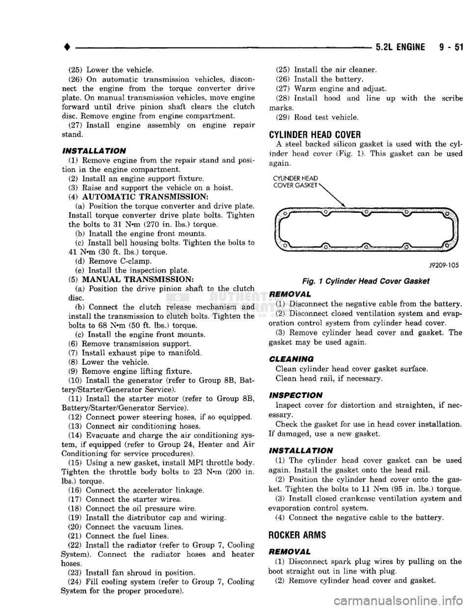
A steel backed silicon gasket is used with the cyl
inder head cover (Fig. 1). This gasket can be used
again.
CYLINDER HEAD
J9209-105
Fig.
1 Cylinder Head
Cover
Gasket
REMOVAL
(1) Disconnect the negative cable from the battery.
(2) Disconnect closed ventilation system and evap
oration control system from cylinder head cover.
(3) Remove cylinder head cover and gasket. The
gasket may be used again.
CLEANING
Clean cylinder head cover gasket surface. Clean head rail, if necessary.
INSPECTION
Inspect cover for distortion and straighten, if nec
essary.
Check the gasket for use in head cover installation.
If damaged, use a new gasket.
INSTALLATION
(1) The cylinder head cover gasket can be used
again. Install the gasket onto the head rail.
(2) Position the cylinder head cover onto the gas
ket. Tighten the bolts to 11 N-m (95 in. lbs.) torque.
(3) Install closed crankcase ventilation system and
evaporation control system.
(4) Connect the negative cable to the battery.
ROCKER ARMS
REMOVAL
(1) Disconnect spark plug wires by pulling on the
boot straight out in line with plug. (2) Remove cylinder head cover and gasket.
Page 685 of 1502
9
- 80 5.9L
ENGINE
•
TRANSFER
CASE
TRANSFER
CASE
ENGINE REAR
SUPPORT
PLATE
INSULATOR
MOUNTING
PLATE
LOWER
INSULATOR
\7"
RAIL
1
J9109-244
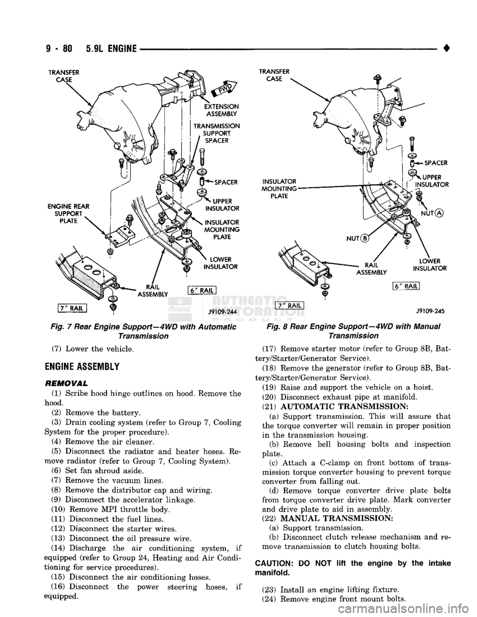
Fig.
7 Rear
Engine
Support—4WD
with
Automatic
Transmission
(7) Lower the vehicle.
ENGINE
ASSEMBLY
REMOVAL
(1) Scribe hood hinge outlines on hood. Remove the
hood. (2) Remove the battery.
(3) Drain cooling system (refer to Group 7, Cooling
System for the proper procedure). (4) Remove the air cleaner.
(5) Disconnect the radiator and heater hoses. Re
move radiator (refer to Group 7, Cooling System). (6) Set fan shroud aside.
(7) Remove the vacuum lines.
(8) Remove the distributor cap and wiring.
(9) Disconnect the accelerator linkage.
(10) Remove MPI throttle body.
(11) Disconnect the fuel lines.
(12) Disconnect the starter wires.
(13) Disconnect the oil pressure wire.
(14) Discharge the air conditioning system, if
equipped (refer to Group 24, Heating and Air Condi
tioning for service procedures).
(15) Disconnect the air conditioning hoses.
(16) Disconnect the power steering hoses, if
equipped.
INSULATOR
MOUNTING
PLATE
SPACER
UPPER
INSULATOR
NUT®
LOWER
INSULATOR
J9109-245
Fig.
8 Rear
Engine
Support—4WD
with
Manual
Transmission
(17) Remove starter motor (refer to Group 8B, Bat
tery/Starter/Generator Service).
(18) Remove the generator (refer to Group 8B, Bat
tery/Starter/Generator Service).
(19) Raise and support the vehicle on a hoist.
(20) Disconnect exhaust pipe at manifold.
(21) AUTOMATIC TRANSMISSION: (a) Support transmission. This will assure that
the torque converter will remain in proper position in the transmission housing. (b) Remove bell housing bolts and inspection
plate. (c) Attach a C-clamp on front bottom of trans
mission torque converter housing to prevent torque converter from falling out. (d) Remove torque converter drive plate bolts
from torque converter drive plate. Mark converter and drive plate to aid in assembly.
(22) MANUAL TRANSMISSION; (a) Support transmission.
(b) Disconnect clutch release mechanism and re
move transmission to clutch housing bolts.
CAUTION:
manifold.
DO
NOT
lift
the engine by the intake
(23) Install an engine lifting fixture.
(24) Remove engine front mount bolts.
Page 686 of 1502
•
5.9L ENGINE
9-81 (25) Lower the vehicle.
(26) On automatic transmission vehicles, discon
nect the engine from the torque converter drive
plate. On manual transmission vehicles, move engine forward until drive pinion shaft clears the clutch
disc.
Remove engine from engine compartment.
(27) Install engine assembly on engine repair
stand.
INSTALLATION (1) Remove engine from the repair stand and posi
tion in the engine compartment.
(2) Install an engine support fixture.
(3) Raise and support the vehicle on a hoist.
(4)
AUTOMATIC TRANSMISSION: (a) Position the torque converter and drive plate.
Install torque converter drive plate bolts. Tighten
the bolts to 31 Nnn (270 in. lbs.) torque.
(b) Install the engine front mounts.
(c) Install bell housing bolts. Tighten the bolts to
41 Nnn (30 ft. lbs.) torque.
(d) Remove C-clamp.
(e) Install the inspection plate.
(5)
MANUAL TRANSMISSION: (a) Position the drive pinion shaft to the clutch
disc.
(b) Connect the clutch release mechanism and
install the transmission to clutch bolts. Tighten the
bolts to 68 Nnn (50 ft. lbs.) torque.
(c) Install the engine front mounts.
(6) Remove transmission support.
(7) Install exhaust pipe to manifold. (8) Lower the vehicle.
(9) Remove engine lifting fixture.
(10) Install the generator (refer to Group 8B, Bat
tery/Starter/Generator Service). (11) Install the starter motor (refer to Group 8B,
Battery/Starter/Generator Service).
(12) Connect power steering hoses, if so equipped.
(13) Connect air conditioning hoses.
(14) Evacuate and charge the air conditioning sys
tem, if equipped (refer to Group 24, Heater and Air Conditioning for service procedures).
(15) Using a new gasket, install MPI throttle body.
Tighten the throttle body bolts to 23 Nnn (200 in. lbs.) torque.
(16) Connect the accelerator linkage. (17) Connect the starter wires.
(18) Connect the oil pressure wire.
(19) Install the distributor cap and wiring.
(20) Connect the vacuum lines.
(21) Connect the fuel lines.
(22) Install the radiator (refer to Group 7, Cooling
System). Connect the radiator hoses and heater
hoses.
(23) Install fan shroud in position.
(24) Fill cooling system (refer to Group 7, Cooling
System for the proper procedure). (25) Install the air cleaner.
(26) Install the battery.
(27) Warm engine and adjust.
(28) Install hood and line up with the scribe
marks. (29) Road test vehicle.
CYLINDER HEAD COVER
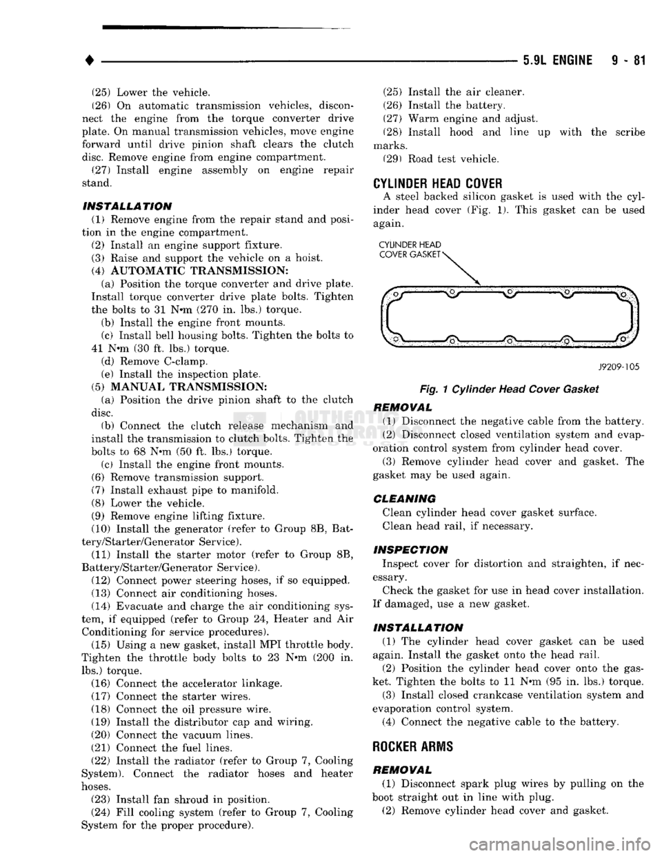
A steel backed silicon gasket is used with the cyl
inder head cover (Fig. 1). This gasket can be used
again.
CYLINDER HEAD
J9209-105
Fig.
1 Cylinder Head
Cover
Gasket
REMOVAL (1) Disconnect the negative cable from the battery.
(2) Disconnect closed ventilation system and evap
oration control system from cylinder head cover.
(3) Remove cylinder head cover and gasket. The
gasket may be used again.
CLEANING
Clean cylinder head cover gasket surface.
Clean head rail, if necessary.
INSPECTION Inspect cover for distortion and straighten, if nec
essary.
Check the gasket for use in head cover installation.
If damaged, use a new gasket.
INSTALLATION (1) The cylinder head cover gasket can be used
again. Install the gasket onto the head rail.
(2) Position the cylinder head cover onto the gas
ket. Tighten the bolts to 11 Nnn (95 in. lbs.) torque. (3) Install closed crankcase ventilation system and
evaporation control system.
(4) Connect the negative cable to the battery.
ROCKER
ARMS
REMOVAL (1) Disconnect spark plug wires by pulling on the
boot straight out in line with plug.
(2) Remove cylinder head cover and gasket.
Page 822 of 1502
•
FUEL SYSTEM
14 • 3
FUEL
DELIVERY SYSTEM-EXCEPT DIESEL
INDEX
page
Fuel Filter—3.9L/5.2L Gas Engine
............
10
Fuel
Filter—5.9L
Gas Engine
11
Fuel Pressure Leak Down Test—3.9L/5.2L Engine
. 8
Fuel Pressure Leak Down Test—5.9L Engine
.... 9
Fuel Pump Capacity
Test—All
Gas
Engines
..... 8
Fuel Pump
Control
........................
5
Fuel Pump Module—3.9L/5.2L Engines
3
GENERAL INFORMATION
Two different types
of
fuel delivery/fuel return sys
tems
are
used.
The
system used with
the
3.9L/5.2L
engine will route excess fuel pressure back
to the
fuel tank through
a
fuel return line.
The
system used
with
the 5.9L
engine will
not
have
a
separate fuel
re
turn line. This system will
be
referred
to as a re-
turnless type.
The
fuel pump module used with
the
5.9L engine will contain
a
combination fuel pressure
regulator
and
fuel filter. Refer
to the
following Fuel
Pump Module
for
additional information
or,
refer
to
the Multi-Port Fuel Injection sections
of
this Fuel System group. A separate frame mounted fuel filter will
not be
used with
any 5.9L gas
powered engine.
FUEL
PUMP
M0DULE-3.9L/5.2L
ENGINES
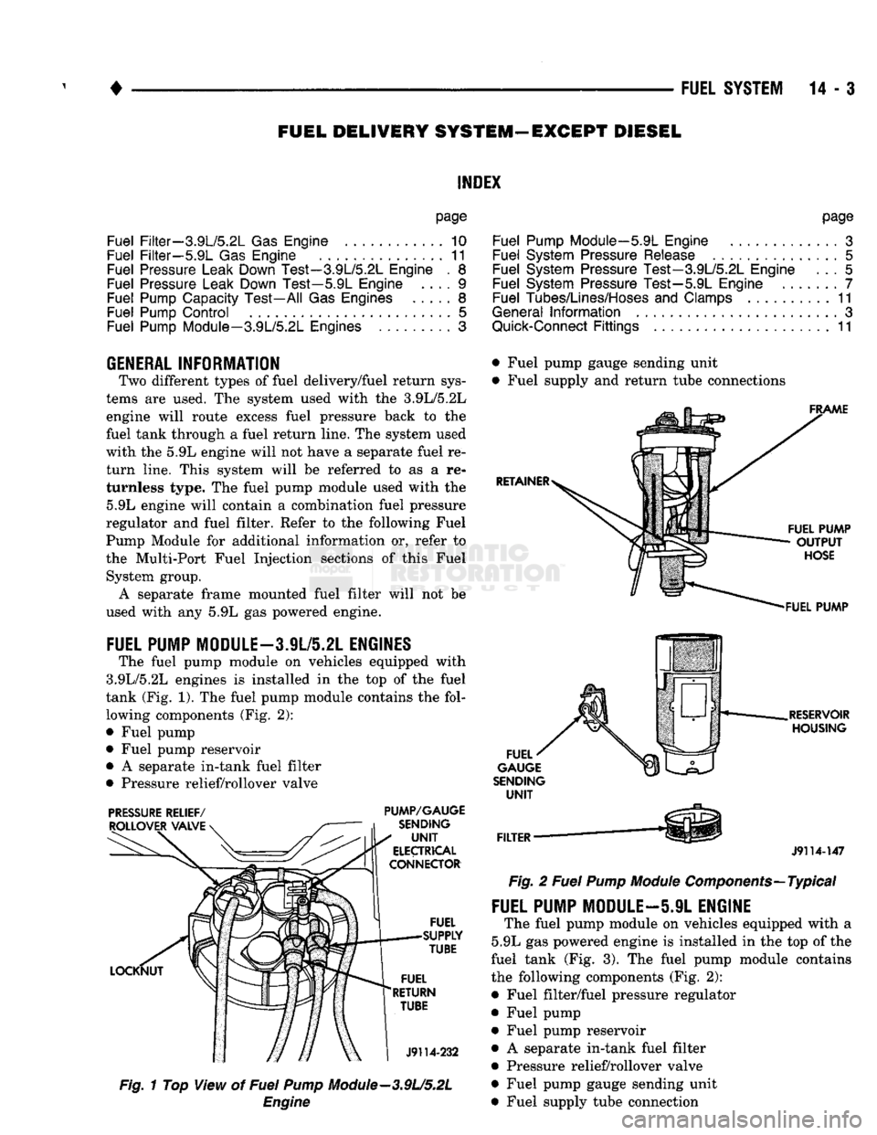
The fuel pump module
on
vehicles equipped with
3.9L/5.2L engines
is
installed
in the top of the
fuel
tank (Fig.
1). The
fuel pump module contains
the
fol lowing components (Fig.
2):
• Fuel pump
• Fuel pump reservoir
•
A
separate in-tank fuel filter
• Pressure relief/rollover valve
PRESSURE
RELIEF/
PUMP/GAUGE
Fig.
1
Top View
of
Fuel
Pump
Module—3.9U5.2L
Engine
page
Fuel Pump Module—5.9L Engine
.............
3
Fuel System Pressure Release
...............
5
Fuel System Pressure Test—3.9L/5.2L Engine
... 5
Fuel System Pressure Test—5.9L Engine
7
Fuel Tubes/Lines/Hoses
and
Clamps
..........
11
General
Information
3
Quick-Connect
Fittings
11
• Fuel pump gauge sending unit
• Fuel supply
and
return tube connections
J9114-147
Fig.
2
Fuel
Pump
Module
Components—Typical
FUEL PUMP MODULE—5.9L ENGINE
The fuel pump module
on
vehicles equipped with
a
5.9L
gas
powered engine
is
installed
in the top of
the
fuel tank
(Fig. 3). The
fuel pump module contains
the following components (Fig.
2):
• Fuel filter/fuel pressure regulator
• Fuel pump • Fuel pump reservoir
•
A
separate in-tank fuel filter
• Pressure relief/rollover valve
• Fuel pump gauge sending unit
• Fuel supply tube connection